 In the footsteps of virtually every information, published under the heading “ENEA — young innovator”, the editor receives many letters. On the envelope address NTTM, young innovators, enterprises, construction companies, farms, and all of them interested in more information about printed in the journal innovative developments. And United by the desire to apply them to achieve a new increase productivity, improve technology, product quality.
 However, this number of requests that had information on a small “Winch in the pocket” (“M-K” No. 6, 1978), the editors have not yet received. Of great interest to a small winch, which was discussed in the article was especially surprising that this linkage was developed for the seemingly narrow application: ease of Assembly operations during the construction or repair of ships. However, according to the letter, the young innovators of the different sectors of the economy saw the possibility of using winches on “his” profile.
On an assignment, our correspondent B. Rawski visited Khabarovsk branch of the Institute of TSNN-its. The explanations of the developers winch V. T. Levchenko and V. P. Makagonova and Institute additional material edition offers today’s young innovators, participants NTTM in the operation log “Implementation”.
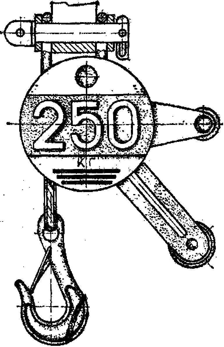
Small mounting winch LR-0,25 capacity of 250 kg is designed for mechanization of handling operations in cramped conditions inside court premises. Until recently, there only used inefficient chain blocks and hoists, and some mounting operations are often necessary to carry out all manually — with the HELP of braces, levers and rollers.
How to explain such a broad interest in design, designed to work in such a specific environment? First of all, it is obvious that it is to satisfy such contradictory requirements to the load lifting device, as the maximum performance, convenience and safety at the lowest possible own weight and size.
Hoist LR-of 0.25 is used for lifting and moving loads weighing up to a quarter of a ton, with weight of only a little more than 3 kg. For comparison, it is five times easier, and lift height it is twice more than the similar American hoists or similar our devices prescribed by GOST.
As noted in a previous publication, these results were achieved primarily due to the successful combination of the functions of the parts of the mechanism. Here, for the first time in such devices, the applied planetary cycloid transmission. The role of nozzles play ties: they not simply connect the cheeks in a single case, and still serve and the drive gear. Flange of the winch drum is simultaneously driven cycloid wheel.
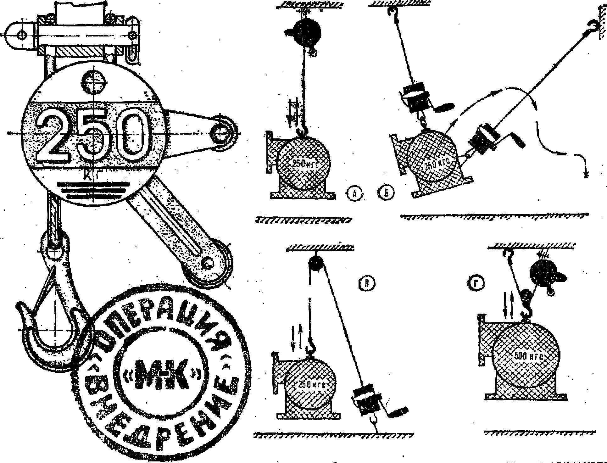
Fig. 1. Mounting a small winch and use it:
A — ascent and descent, — the movement of the load along a complex path In the ascent and descent through the block, G — ascent and descent with the use of pulley.
According to numerous requests of readers here is a more detailed diagram of the device of the winch (Fig. 2-4). Two cheeks, fastened with a pin tooth, constitute the actual body of the whole mechanism. Inside it on bearings is free to rotate the eccentric shaft, the eccentric journal which is also freely planted the drum flanges. The last teeth included in the planetary gearing located at the calculated initial circle of nozzles (they are on unit. more than teeth). Two nizhnelomovskih the pin tooth is made cutouts for the passage of the rope; on the top two loosely fitting loop for the suspension mechanism.
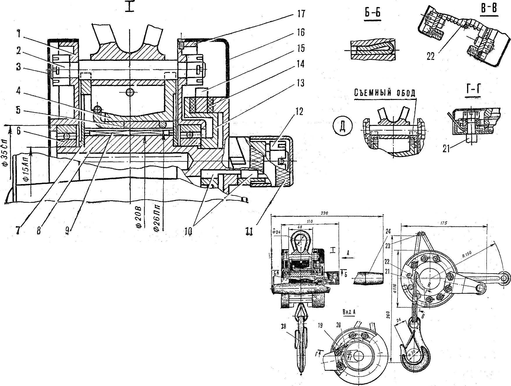
Fig. 2. Scheme small winch:
1 — left cheek, 2 — nut M8 3, 16 covers, 4 — drum, 5 — wedge, 6 — bearing (60202, GOST 8338-75), 7, 14 — ring, 8 — shaft 9 — bearing (942/20, GOST 4060-60), 10 — key (5X5X8 mm), 11 — cap, 12 nut M10 13 — disc, 15 — ratchet, 17 — right cheek, 18 — hook 19 — spring 20 — dog 21 — rope 22 — nozzle, 23 — ring, 24 — arm; D — variant of the drum with a removable rim flanges.
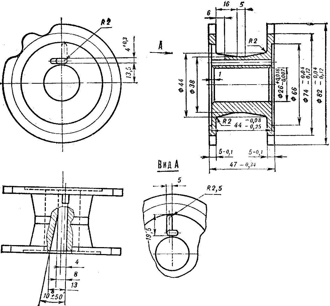
Fig. 3. The winch drum.
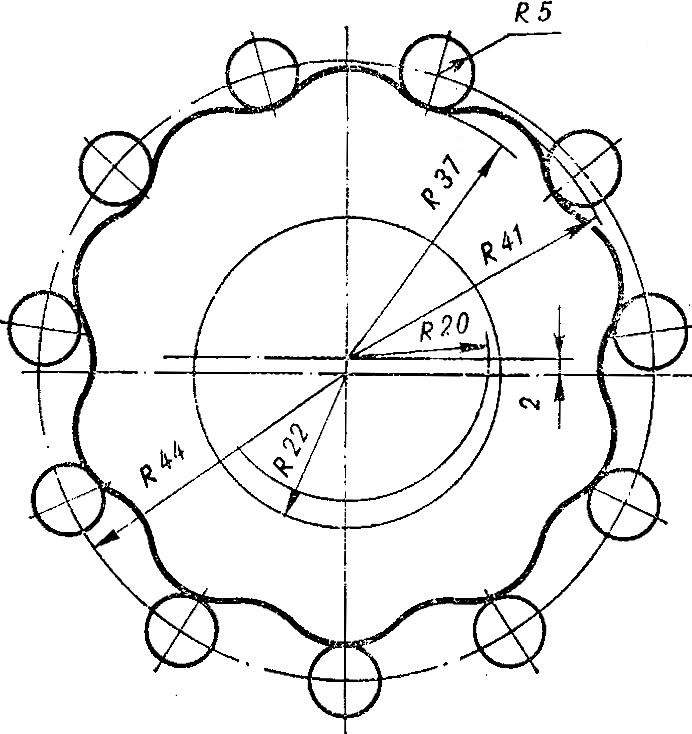
Fig. 4. The scheme of engagement of the flange with the pin tooth.
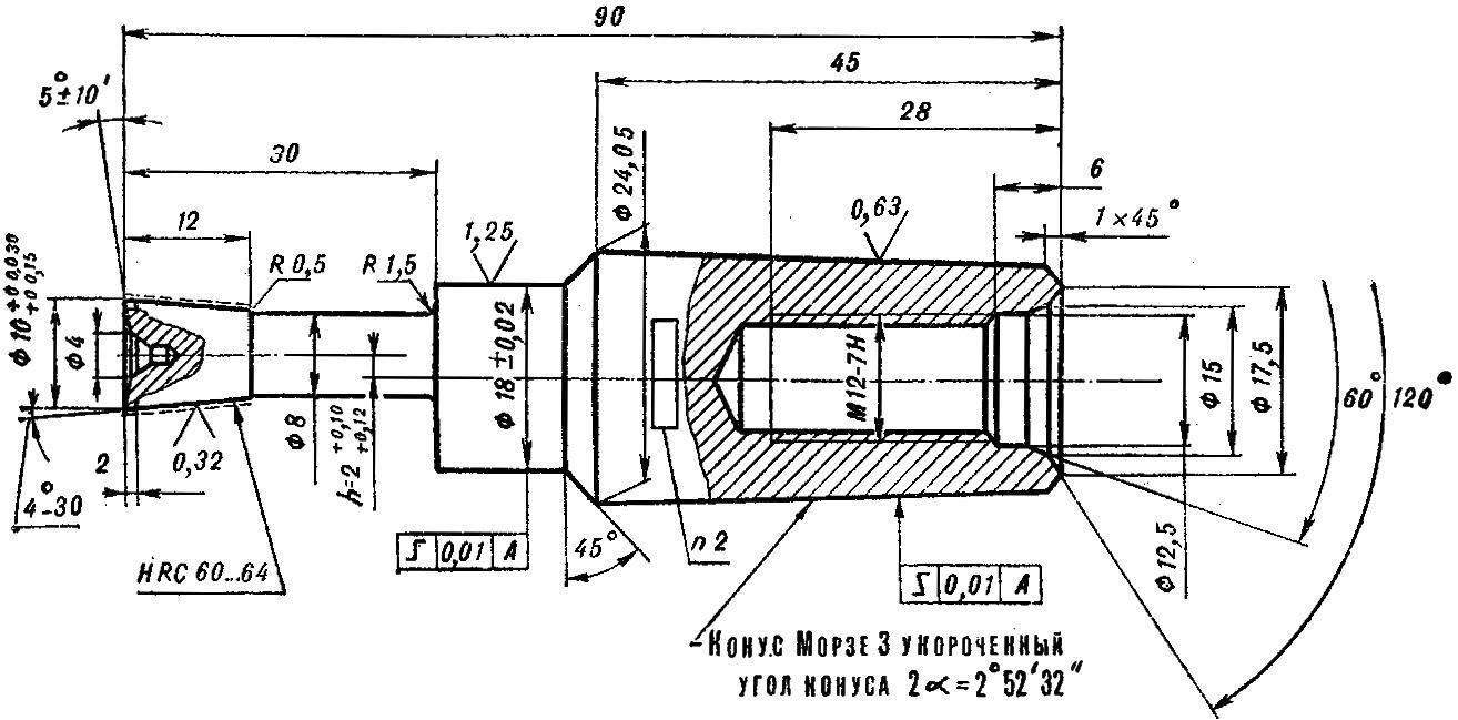
Fig. 5. Scheme round shaping cutter IG-90 for cutting of teeth of the flange.
The reported rotation shaft of the drum by means of a handle or chain option — replaceable drive sprocket. Both of these items together with the ratchet mechanism and the brake discs also serve as automatic load pressure brake. When the pawl of the ratchet mechanism is precluded spontaneous lowering of the cargo: it can move down only by rotating the handle counterclockwise. Auxiliary handle on the housing serves to hold the mechanism at work.
The principle of operation is as follows. When rotating the handle clockwise the drum flange makes the vibrational-rotational movement with eccentricity 2 mm. Catching with nozzles, it is due to the difference in one tooth for one revolution of the eccentric shaft journal rotates counterclockwise by one step, i.e., completes one full revolution during ten revolutions of the handle.
With a winch LR-of 0.25 it is possible to perform a variety of Assembly and transport operations: to raise to lower heavy objects to pull and to move loads on a length of rope. When using multiple winches, fixed ka of ceiling and wall mountings, you can apply the load along a complex curve (Fig. 1).
A few comments presented here are diagrams and parts of the winch.
The drawing drum is made based on mass production, in which the formation of epicycloidal tooth profile can be performed simultaneously on both flanges of the drum cutter with special profiles or turning and backing machine specially made for the copier. The use of shaping cutter IG-90 for the intended purpose in this case is impossible, since its length (30 mm) is insufficient for drum (47 mm). But with the help of shaping cutter can be manufactured copier in full size for turning and backing machine, and the copier is to form the teeth on both flanges simultaneously. Technology is also much simpler if the cheeks (flange) of the drum is removable to make: then both cheeks together can be mounted on gear shaping machine and shaping the tooth using the same shaping cutter IG-90. It was executed all epicicloidali flange from the first batch of winches.
In both cases, to simplify the technology can proceed as follows. First cut teeth on the bead directly shaping cutter or with the use of made with the help of copier. Then with an accuracy up to 0.01 mm to measure the resulting actual height of cut his teeth as half of the difference between the circumferences of the projections and depressions. And finally, to perform shaft eccentricity equal to half the effective height of the tooth with a tolerance of — 0,01 (-0,05) mm.
The calculation of the transmission when conecentration epicicloidali engaged (see Fig.) made according to the formulas from the book by V. N. Kudryavtsev “Planetary gear” (Moscow, “engineering” , 1966). The radius of the circle centers of the nozzles is 44 mm; the selected constructively, placing the drum rope Ø 4.1 mm. Number of nozzles — 11; received in accordance with the optimal forces on the handle from 8 to 12 kg, dimensions of the handle, as well as the conditions that the transmission difference between the teeth of the drum and the pin tooth is 1 and the gear ratio is 10. The radius of the pin is 5 mm from the strength and placement of all nozzles on the circumference of a radius of 44 mm And finally, the eccentricity of 22 mm is selected from the conditions for obtaining a correction factor (see formula 338), 0.15 and 0.5.
The correction factor (formula 341) is 0.5. The radii of the centroid, the initial circles (formulas 338 and 339) — 22 20 mm. and the Radii of the circumferences of the protrusions and depressions of the asterisk (flange) of the drum (the formula 342 and 343) is 41, and 37 mm.
Setting machine
for cutting unicentertng epicycloidal tooth profile shaping cutter IG-90.
Drawing data: number of teeth Zø — 10. the diameter of the stuffing horn (shaping cutter) Dd = 10 mm, diameter of protrusions Dto 82 mm, the diameter of the depressions DVP — 74 mm, the eccentricity of h — 2 mm.
The ratio between the angular velocity W of rotation of a spindle of shaping cutter and cut part is defined by the formula:
Spindle W = W of the part * Zsh.
From this it follows that the formula settings in the machines passports valid for this case.
Guitar tuning division gear shaping machine 5В12:
Zd/ZW= 1/10 = (24*25)/(80*75),
where Zd is the number of teeth of the shaping cutter.
Guitar tuning division bench 5M14:
2,4*Zd/ZW = 2,4*1/10 = (34*60)/(85*100).
The distance between the axis of the spindle of shaping cutter and the axis of a cut detail at the beginning of processing:
L = Din/2 + Dd/2 + h = 82/2 + 10/2 + 2 = 48 mm.
Is the same distance at the end of processing:
L = DVP/2 + Dd/2 + h = 74/2 + 10/2 + 2 = 44 mm.
(The calculation is performed P. G. Lukyanenko using the book “Gear and worm gear” edited by N. I. Kolchin, Mashgiz, 1959 and passport machines model 5В12 and 5М14.)
Recommend to read
 FOAM BELT
In older toilets hinged toilet cover with noise hits the pipe spillway, and the two contact surfaces in this place over time, injured. This can be avoided if reinforced pipe is a foam... Georgia tourist
Georgia — the country is amazing, not just amazing, but, unfortunately, unfairly deprived of attention. Tourists in Tbilisi should visit the cable car, which immediately attracts...
