a mini-tractor .
The design describes the mini-tractor I have a second account. In the first model positioned the engine in the rear of the frame, to dispense with the propeller shaft in the powertrain. But the car suddenly, I behaved badly in running, especially on hills and under load. Tried to put in front counterweights, but they significantly weigh down the design and helped a little.
In the end, decided to remake the tractor and Paramonova units, installed them according to the classical scheme. The result is a completely different, better design, and now runs a mini-tractor is, and so I decided the hearth to pour it with the readers of the respected journal—DIY and technology enthusiasts.
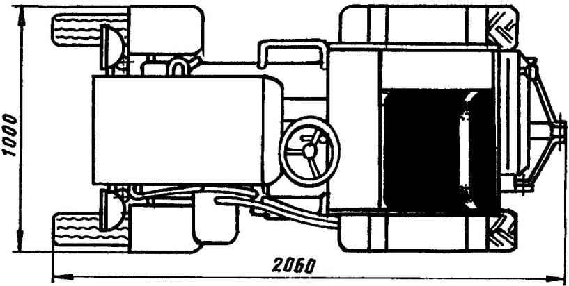
General view of the mini-tractor:
1 — frame; 2 — shift stage (gear shift of the motorcycle “Ural”, modified); 3—front driven wheel (sidecar FDD, the tire of the scooter, 2); 4— front fender (steel sheet s0,8, 2); 5 — engine (UD-25, N = 14 HP, diesel); 6 — beam (farm equipment, 2); 7—hood (steel sheet s0,8); 8 — hydraulic oil tank (farm equipment, capacity 4 l); 9 —the hydraulic hoses (agricultural equipment); 10— the gear selector lever; 11 — a casing of the propeller shaft; 12—seat; 13 — fuel tank (capacity 20 l); 14—hydraulic cylinders (agricultural equipment); 15— rear drive wheel (from the car “Volga”, buses from the car “Niva”, 2); 16—steering wheel; 17—tool kit (from the farm); 18—silencer; 19 — front axle (steel pipe d57); 20 — gear shift (from the car “Zaporozhets”)
The main advantage of the design of his mini-tractor that it is assembled primarily from aggregates, mechanisms and units commercially produced machines, and therefore not scarce. If necessary, when a failure of parts to find not so difficult.
The frame is of simple rectangular shape, welded. Form its pair of side members and two of the traverse: front and rear (all these elements are made from steel plumbing pipes with diameter of 57 mm).
Frame:
1 — bracket front axle; 2— front cross member (steel pipe d57); 3 — bulkhead (steel pipe d57, 2); 4— cross bar (steel pipe d30,2); 5 — bracket “grip” rear axle (steel sheet s5. 2); 6 — support legs-the arc of the propeller shaft (steel pipe d30); 7 — rear cross member (steel pipe d57 and channel No. 8); 8 — support brackets mounting engine (sheet s5); 9 — the mounting bracket dual mounting (sheet s5); 10 — support bracket gear lever (steel sheet s5); 11 —bracket, transmission mounting (sheet s5); 12— reference sites of the mounting bracket of the propeller shaft (80×80 area); 13 — kickstand (steel pipe d30, 2); 14 — jumper (steel pipe 30); 15 — eye mount front axle
Traverse welded to the front bracket with lug (for connecting the lug of the front axle). End cross member reinforced with a steel channel number 8 — he put on the pipe and welded to it. The ends of the channel bent at 90° back — they form brackets for attaching thereto rods extending from hydraulic hitch.
Between the side members at the front of the frame are mounted two cross-beams, between the longitudinal beam and in the corners of the frame under engine mounting brackets. In the rear part of the frame is welded of two arched stands with platforms — they subsequently assembled the bearing housings for the shaft of the drive sprocket of the chain transmission.
Outside to the side members in the middle part thereof is welded arc for foot pegs, curved from the same tubes as the crossmember, and the rear brackets of the rear axle. Some additional elements, for example, the supports of seats, dashboard stand, and others, was welded to the frame during Assembly of the tractor.
Chassis mnni-tractor:
1 — front driven wheel (2 PCs); 2 — engine; 3 — coupler attachment auxiliary gearbox to the engine crankcase (steel strip 40×5); 4— dual; 5 — the lever of a gear of the auxiliary gearbox; 6—control lever-clutch; 7—the lever of a gear change; 8 — the driveshaft (from the farm); 9—elastic rubber coupling (from the car “Lada”); 10 — body with a support bearing 80204 (agricultural machinery) shaft sprocket (2 PCs.); 11 — sprocket (z = 24, scooter “Tula”); 12—shaft sprocket (steel 45); 13 — drive chain (t = 12,7); 14 — rear driving wheel (2); 15 — shaft support sprocket with bearing 80204 in the housing (agricultural machinery); 16 — sprocket driven (z = 38, from scooter “Tula”); 17—”stocking” axle (from the car “Volga”, short, 2 PCs.); 18 — the side shaft (from the car “Volga”, short, 2 PCs.); 19 — a gear shift; 20 — an arm of the shift lever; 21 — frame; 22 — front axle
Front axle:
1 — front wheel (2 PCs); 2— steering knuckle (motorized FDD, 2); 3 — strut (steel pipe d57, 2); 4 — beam (steel pipe d57, 2); 5 — bracket-lug suspension bridge to the frame; 6— solitaire (STZ, sheet s3. 2); 7 — spacer sleeves (pipe d30,4 items); 8 — M8 bolts (with lock washers) securing the steering knuckle to the bridge (4 PCs)
Rear axle (with bearing cap support shaft not shown):
1 — rear wheel; 2 — the “stocking” axle (2 pieces); 3— axis (2); 4 — gear box with differential; 5 — counter shaft sprocket; 6 — chain (t = 12,7); 7 — bracket “stocking” to the frame
The holes in the brackets for mounting assemblies, mechanisms and components are also mostly pinned in place after pre-kanonaki. And componica, I must say, it turned out so dense that the oil tank of the hydraulic system even had to take out from under the hood outside of the engine compartment.
The engine mini-tractor — UD-25: two-cylinder, four-stroke, forced air cooling, with power of 14 HP used It without much trouble, as he had regular magneto and kick starter. Only on the front end of the crankshaft mounted pulley from Lada to drive the oil pump NSH-32 hydraulic system for remote control of mounted implements. Pulley finished bore. V-timing belt — cars. Silencer set also “Zhiguli”. First, as usual with tractors, the exhaust tube up. But the smoke fell straight face. So I turned and Ayval the end of a pipe under the floor.
Revision “stocking” from the car “Volga”:
1 —housing shaft bearing; 2—”stocking”; 3 — bracket “stocking” to the frame; 4 — flange mounting “stocking” to the transmission of the car ZAZ; 5 — cut the half of the housing and the main transmission
Revision of the driveshaft from the car “Volga”:
1 — driveshaft with the flange of the wheel; 2 — finger (from ZAZ); 3 — crackers (from ZAZ); 4 — cut the spline end of the driveshaft
Drivetrain the mini-tractor is not quite normal — it two the gearbox (transmission). The first (with clutch) took from an old motorcycle “Ural”. Dignity “Orlovskoe” box — in its compactness and that it successfully mated to the 2-disclaim grip. Box docked to the engine by means of an adapter, since the contours of the crankcase and gearbox are almost identical. The adapter is a ring bent from a steel strip section 40×5 mm (butt welded). The ring is welded in place stud M8 facing both sides. One end of each pin enters a mounting hole in the crankcase of the engine, on the other hand, the checkpoint, which serves as a dual. For shifting to the place of pedals mounted lever.
“Orlovskoe” box left only two gears: the first — and as a working (she serves as an intermediate gear) and fourth (direct, that is to say, transmission) — it transfers the torque from the engine via the cardan shaft at the leading thestock chain transmission without changing the number of revolutions of the motor. The remaining transmission (second and third) turned out to be unnecessary, since the change of speeds is the second CAT from the car “Zaporozhets”. A big advantage of this box is that as it (in its housing) are the main transmission and the differential.
The driveshaft — Assembly. The rubber coupler took from the car “Lada” and other nodes, including housing with bearings 80204 — from different end-of agricultural machinery. Between the arched supports of the frame is mounted on a short shaft drive (small) sprocket of the chain transmission. From it the rotation is transmitted to a large driven sprockets, seated on the input shaft next to the transmission. Both stars of the scooter “Tula”: leading small (24 tooth) is taken from the secondary shaft; counter shaft (38-bevel) — from the hub of the rear wheel. Connecting the drive chain sprocket has a step of 12.7 mm. chain Tension is produced by the lining plates under the bearing housings shaft sprocket. I note the peculiarity, or rather, need: bearings used only closed: with protective washers on both sides 8000 series (with seals — series 180000).
Driveline:
1 — flange of the output shaft of auxiliary gearbox (from a motorcycle “Ural”); 2 — universal joint with a splined tip (from agricultural equipment); 3 — the main driveshaft with the splined sleeve (from the farm); 4 — front bearing with bearing 80304 in housing; 5 — a shaft with splines of the drive sprocket; 6— sprocket; 7—remote sleeve; 8 — rear bearing with the bearing in the housing 80304
The second transmission mini tractor (tridtsatimetrovogo car “Zaporozhets” ZAZ-965-M) located under the frame — it performs its regular function. Its the input shaft I had to lengthen and put an end to a bearing 80202 body is secured in the back of the clutch cover. From the second gearbox rotation to the rear driving wheels is transmitted through the axle shaft. The axle shaft are enclosed in “stockings”. And those and others are taken from the rear axle of the car “Volga” GAZ-24. “Stockings” shortened (cut from bridge Carter, the main transmission), and to the ends of the welded flanges for connection to Zaporozhskiy CAT. Holes in flanges are drilled strictly for the holes in the respective tides of the box. Axle is also shortened, and their ends are modified and made the same as that of the semi-axes of ZAZ. Fingers and crackers used from “zaporozhtsa”.
Rear wheel is also taken from the car “Volga”. But since they are leading, “shod” in tires M + S (mud and snow) developed cleats (from the car “Niva”).
Front axle home-made, welded in the shape of P of the same pipes that frame. The connections of beams and uprights are reinforced with gussets. The node swivel axle beam to the frame (abalone from u-joint) welded to the top beam in the middle.
Front control wheels along with the axles and steering knuckles are used from a wheelchair. The rubber on the wheels wore motorolleri. Adjustment of rasala wheels made lining washers between the uprights of the beam and the steering knuckle.
Diagram of throttle control:
1 — the pedal “gas” (from the car “Volga”); 2— pull a lever, 3 — lever foot control “gas”; 4— the General axis of the levers; 5 — stationary sector (from the car “Moskvich-400”); 6— a bolt of fixing of the hand lever; 7 — the lever of a hand control “gas” (from the car “Moskvich-400”); 8 — throttle thrust
Brake system — from “Volga”, but it operates only on the rear wheels, however, and that is enough.
Steering gear — cars, but it used angle gear from some kind of agricultural machinery. Diagram of a trapezoid — the usual, of two rods from the car “Volga”. One pull connects the steering fry knuckle left wheel. The other cross that connects both arm and has a coupling for adjustment of toe.
On the instrument panel mounted speedometer, oil pressure indicator the engine, the ignition.
The fuel tank holds about 20 liters of diesel. In the hydraulic tank, pour about 4 l of oil. The hydraulic system serves for lifting and lowering the mounting teleoperative guns. In cachette those in plowing use odnoimennyi the plow, and in interrow processing of crops — two Hiller.
V. KONOVALOV, Kislovodsk
Recommend to read UNUSUAL THINGS MADE WITH YOUR OWN HANDS Many of us love tinkering with their hands various things. But few dare to really costly, complex and lengthy projects. Present to your attention a development tank, a helicopter, a... MERKAVA from ISRAEL According to the program of development of the armed forces of Israel military industry of the country by 1989 was able to create actually a new Merkava tank (Мегкаvа) MK.Z. The Lebanese...
Scroll back to top
 I’m a longtime admirer of the magazine “modelist-Konstruktor”. In the publications of improvised technique find many useful, and most importantly — increased creativity and a desire to design your own technique. I also homebrew with the experience. In recent years, made three tillers for themselves and their relatives. For processing country of six acres, but still planted mostly fruit-berry cultures, these machines are very suitable. But if the plot is bigger, then their effectiveness is eroding. Without a tractor here not to do, even a small mini. Here I am, before you take a plot of land on the former state farm field is abandoned, decided to make and made a good assistant — a mini-tractor.