
 (Continued. Beginning at No. 10, 1975)
 5. THE MOST CRITICAL NODES
Traffic safety and ease of control of desired self-made car, probably even more than serial. After all, “home” often run not too experienced drivers, and passengers do not have such protection, what is the serial car pressed steel body. So Amateur avtostroitel should pay particular attention to steering and brakes, and perfection of these mechanisms will have to achieve by simple means and without weighting of the car. The correct device of steering control and increase the vehicle stability, prevent excessive tire wear.
Under normal for any passenger car independent suspension of the front wheels steering is accomplished with a split lateral traction, and the traction drive is performed either from the steering gear (worm gear, rack and pinion, etc.). or from the toothed rack, which serves as the middle level thrust. Such a system is called “steering the automotive-type”. It thus (in contrast to motor and other systems), as recorded in the “Requirements of the traffic police,” should this node have a homemade car.
Of the industrial designs for self-made cars are suitable with minor modifications rack and pinion system from sidecars and systems with a split rod from cars “Moskvich”, “Zaporozhets” and vases (Fig. 1). These units can be rented and a role model. In the latter case, however, you need to consider some General provisions on design of steering gear. They are as follows.
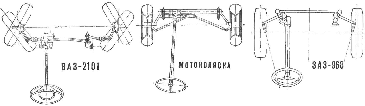
Fig. 1. Steering domestic vehicles
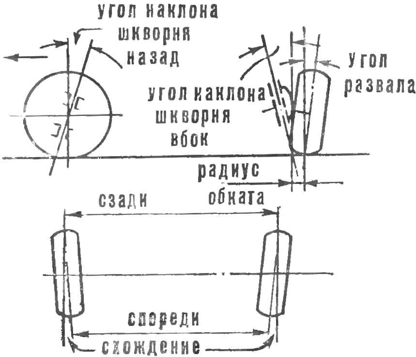
Fig. 2. Installing wheels
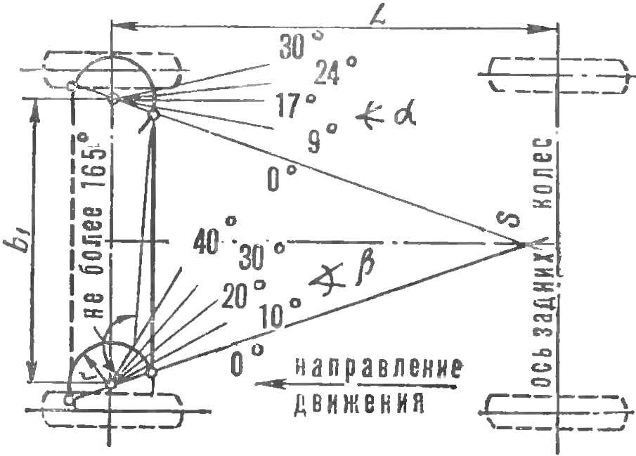
Fig. 3. The construction of the steering linkage
Installation of wheels (Fig. 2) determine the angles “collapse” (of 0.5—1.5°), tilt of the king pin to the side (3-7°) and backward (0-4°), the magnitude of toe (about 3 mm) and the radius of the running wheel around the axis of the pin (30-50 mm).
For proper construction of the steering linkage need to connect by straight lines the points of restraint of the axes of the king pins and front wheel point located in the middle of the axis of the rear wheels (Fig. 3). On these lines must lie the centers of the rotary joints of the levers. It is necessary that the position of the point 5 given such a direction lever that turns both wheels obey the relationship:
ctg α = ctg β + b1/L,
where α and β are angles of rotation of the wheels, external and internal (relative to the center of rotation), b1 — the distance between the axes of the pins, and L is the wheelbase.
To draw the model error against the estimated provisions, at β = 20° must be equal to zero. The error on large angles are not important, as sharp turns are made at low speed. If there is an error the position of the point S must be changed. For a relatively korotkobazny homemade car enough the greatest angle β equal to 30°.
Here is an example. Distance b1 is equal to 1 m, the base — 2 m, that is, b1: L = 0.5. Then at the angles of β, equal 0-10-20-30-40°, the angles α of approximately 0-9-17-24-30°.
To avoid “jamming” rods at the extremes, the greatest angle between lateral rod and a turning lever shall not exceed 165°.
Transverse thrust is more profitable to place behind axis of front wheels: here it is protected from shocks and prevents the device of the brakes, as its length is less than b1. However, this may reduce the space in the body, necessary for the accommodation of the people, and thus force to increase the length and the base of the car. If it is put ahead of the axle, you have to “split hairs” with the brakes: the end of a rod go and the area of the wheels. It should be noted that the thrust is located in front of the axle, works mainly on stretching and can be made less rigid than the back. To reduce the load on the parts, it is necessary to make the swivel arms as long as possible.
If the suspension with the transverse leaf spring (Fig. 4A), longitudinal (Fig. 4B) or long wishbones permissible to divide the traction on the two links-drive them from a single average or offset (to the side of the steering column) bipod. However, the wishbone is often short. That’s why transverse rod usually has to be divided into three levels (Fig. 4B) when installing, except for the Pitman arm, idler arm. Power steering rack can also be two-tier (Fig. 4D) or three-tier (Fig. 4D). To eliminate excessive oscillations of the wheels, worn suspension parts and steering from mismatched mutual displacement of the centers of hinges of the transverse thrust (between the middle and extreme parts) should be placed close to the axes of the suspension arms.
We strongly recommend to apply for the steering drive ready automotive parts: ball fingers, collets, springs etc., only changing the length of the rods. In particular the processing of the finished thrust (cutting, welding, implementation of threads) needed her vacation and subsequent normalization.
Swing arms, axles, suspension struts, idler arms, Pitman arm need to make high-grade steel (e.g. ST. 35, 40 NM, 30S, etc.), the finished part is to harden and loosen, bringing the hardness to HRC 32-36.
The steering mechanism should also borrow from the car, following the revision if it is needed, the same requirements as for said parts of the drive. It is often not possible to place the steering wheel comfortably against the seat (see No. 1) at a given position of the steering mechanism. Then the shaft is divided into two parts and connect them with a soft joint or a simple (two forks and crosses) gimbal. Shaft diameter 20-22 mm. In those cases when it is necessary to change the position of the steering gear housing against the factory, provide a new hole with plug for filling lubricant. Upper steering shaft bearing (in the back) is useful to provide rubber or plastic grommet.
The gear ratio in the steering actuator must be within the unit. Accordingly, the selected length of the levers. Calculation of in is performed by the formulas:
in = f/c · d/e = 1
— for two transverse thrust and
I n = d/c
— for three-unit traction (see notation on Fig. 4A, b).
Gear ratio rack and pinion control is selected in the range of 10-12. It is calculated by the formula:
i = d·cosy/r·cosσ (see Fig. 4G, l).
The approximate size of slats shown in figure 4. The number of gear teeth 7-10.
When linking with the forward control of the driver’s seat all this remains valid, but between the steering mechanism and trapeze introduces the intermediate elements. Fry connects steering drag link with duplechin lever acting on the transverse rod (Fig. 4E). Possible and this option steering gear: the steering wheel is mounted on a very short shaft and the steering mechanism is about transverse thrust as it was on the base car; both disconnected node connected to two or three shaft units — or with the hinges between them, or with gears (Fig. 4 W, z). This drive is slightly more difficult others, but has the advantage that the steering mechanism is in the most lower front part of the body; falling on her impact in the event of hitting does not cause injury to the driver.
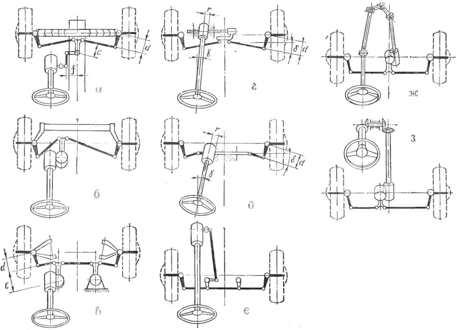
Fig. 4. Various schemes of the steering linkage:
a — two-link with transverse leaf spring; b — at the trailing arm of the suspension; in the three — tiered with a pendulum lever, a rack and pinion; d — two-link; d — three-tier; e — duplicem lever; W — with cardan shafts; z — bevel gears.
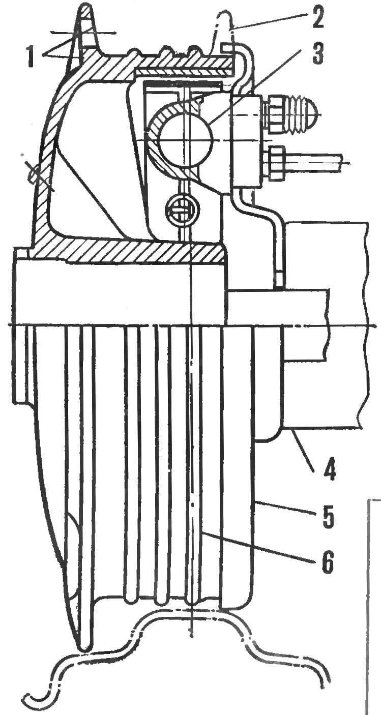
Fig. 5. Changed brake motorcycle K-750 with hydraulic drive:
1 — crown wheel attachment, 2 — remove the drum part, 3 — cylinder, 4 — bracket suspension, 5 — disc brake, 6 — brake drum.
When driving with a full load on dry asphalt road and, at the greatest pressure on the brake pedal, the latter must provide the vehicle the stopping from the moment you push on the pedal to a full stop not more than 6 m from a speed of 30 km/h and not more than 16 metres from a speed of 50 km/h. This requirement corresponds to the brake, which on 1 cm2 surface linings have 1.5—2 kg total mass of the car.
In a small wheel used on the micro cars, you can incorporate brake drums with inner diameter of about 200 mm and a width of the working surface 30-35 mm. For the two-seater micro-car, only with total weight not exceeding 600 kg enough two brakes on the rear wheels, and the quadruple of the car needs brakes on all wheels. For our purposes, the most suitable brake Irbit and Kiev motorcycles. When installed on the car, they have to be somewhat redesigned. Cover replaced or chiseled from a sheet metal brake shield. Drive you can save motorcycle, rope; then continue activity Cams and their levers, and pads with lining.
More efficient and modern drive — hydraulic. Its details entirely (with the exception of the length of the tubes) to use cars Zaporozhets, Moskvich and VAZ. providing on boards brake pad for cylinder mounting and shortening the pads (Fig. 5). You can apply in double a homemade car and the brake from the sidecar.
Laying pipes and hoses to brake, avoid steep their kinks, and abrupt changes in configuration when operating suspension. The ends of the shortened (vs serial) of tubes need to be equipped with double beading.
The Parking brake runs rods and cables from manual lever. Leveler balancer can be replaced total for both wheels cable draped over fixed to the lower end of the lever roller.
Section lead candidate of technical Sciences Y. DOLMATOVSKY
Recommend to read
 ECONOMICAL LIGHTING
In large apartments and private homes in the evening and at night it is difficult to follow the dark corridors or staircases to the touch to find the button and turn the lighting. ... WINGED “FIATS”
Fighter FIAT CR-32. The plane, which will be discussed, for the five years preceding the Second world war, was a symbol of Italian fighter aircraft. Small, nimble, he observed the...
