More and more often, the editorial mail receives bulky packages with drawings and descriptions of homemade micromotorcycles. Their principal difference from designs of earlier years is a successful combination of standard and homemade units in the construction. A second important detail is a sharply improved appearance and bold design solutions.
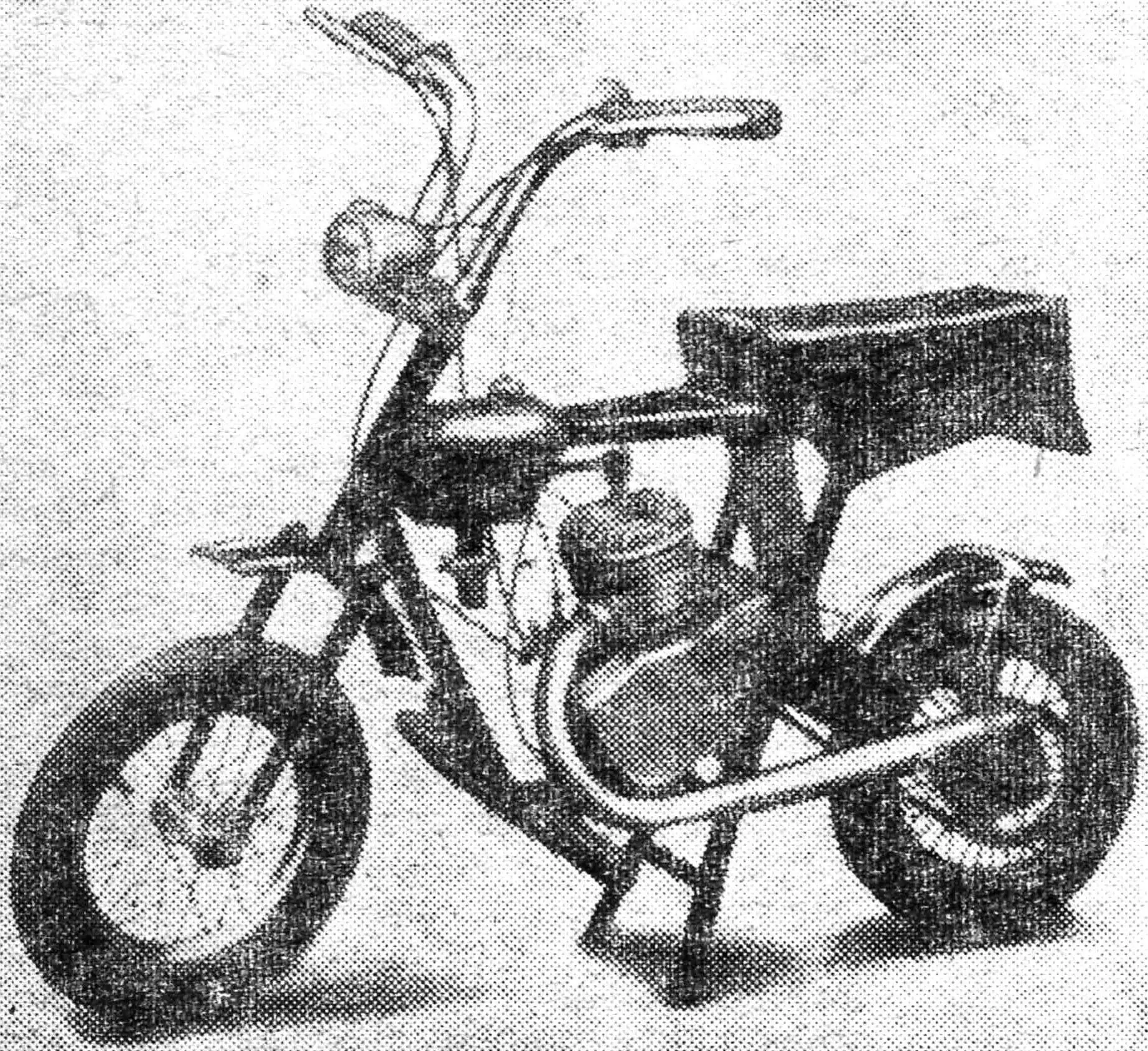
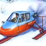
On these pages we present to readers a micromotorcycle to which the characteristics stated above apply in full.
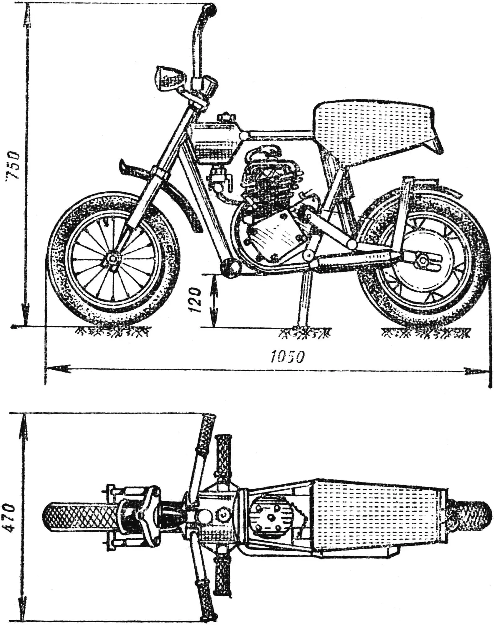
When laying out my micromotorcycle, I came to the idea that the fuel tank could be made part of the power frame. This made it possible to reduce the weight of the machine and give it more dynamic shapes. Using oval tubes for the frame allowed the “Kuznechik” to be strong enough, light, and, importantly, compact. With the handlebars folded, its overall dimensions fit inside a box of 195 × 750 × 1650 mm, so it can be placed freely in a car trunk, in an elevator, and even under a bed.
The frame of this micromotorcycle is welded from thin-walled (wall thickness up to 1.5 mm) steel tubes. All frame elements (except the fuel tank) are joined by electric welding, not all at once but in stages as separate assemblies with intermediate straightening, because distortion was considerable. The fuel tank parts were joined by gas welding.
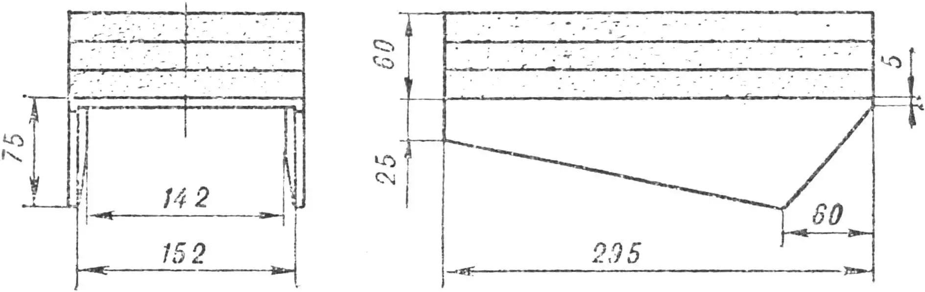
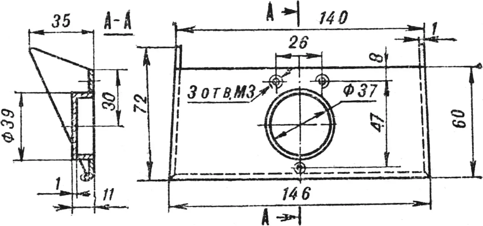
Now in more detail about the motorcycle and the order of assembly. The fuel tank serves not only as a container for fuel but also as a structural member of the frame. Its base is a steel tube Ø 102 × 1.5 mm. After layout and cutting, a tube Ø 20 mm and 108 mm long is welded to it. Then steel plates are laid on the end faces of the housing, traced along its contours, cut out, and welded on.
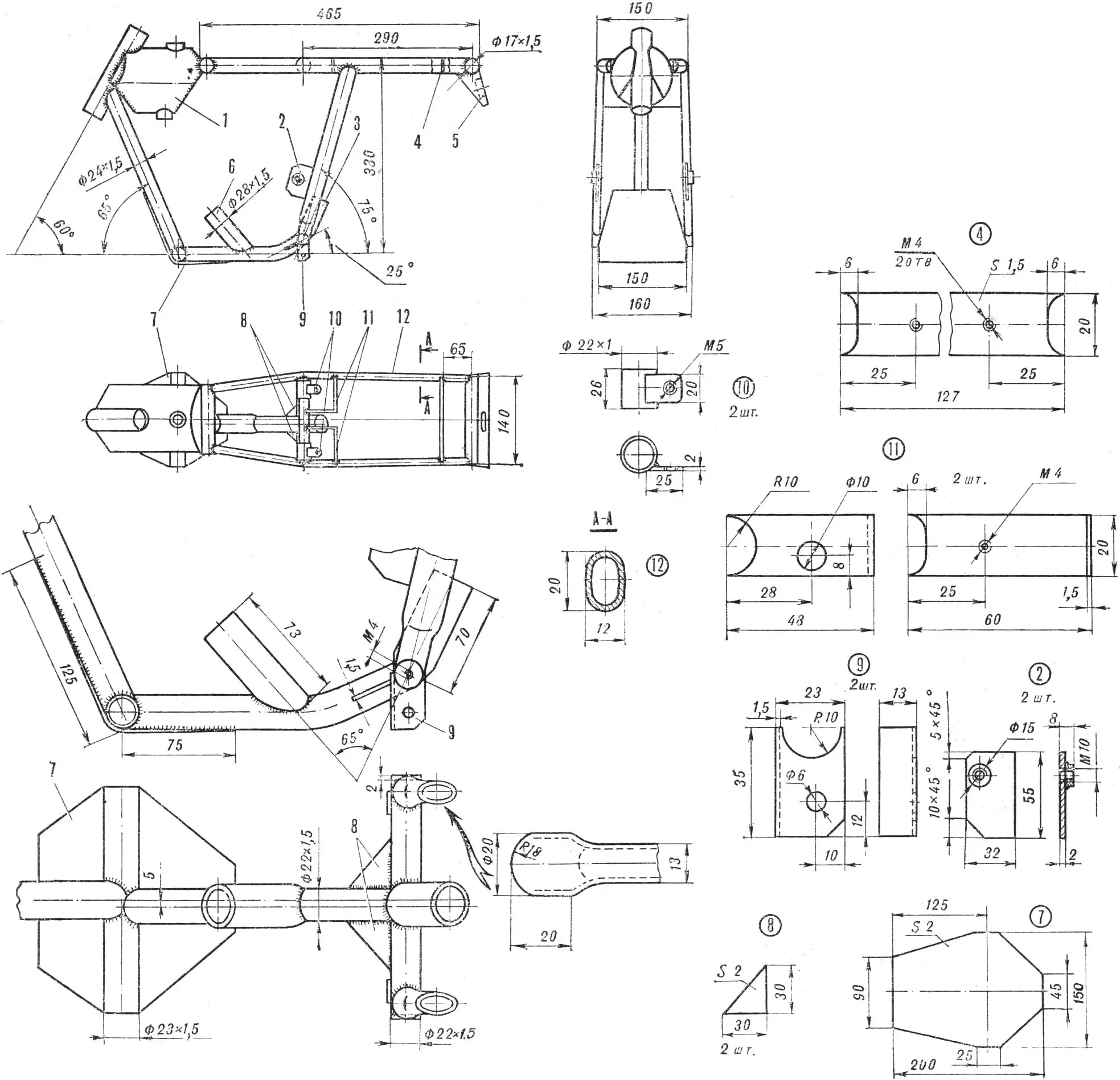
1 — fuel tank, 2 — gusset bracket, 3, 6 — engine mounting brackets, 4 — tool box mounting strip, 5 — visor, 7 — deflector shield, 8 — gussets, 9 — stand mounting brackets, 10 — clamps, 11 — upper bracket of the rear shock absorber, 12 — oval tube.
Next the frame head is fitted and welded, and openings are cut in the housing for the tank neck and fuel drain fitting, which are then soldered into the tank.
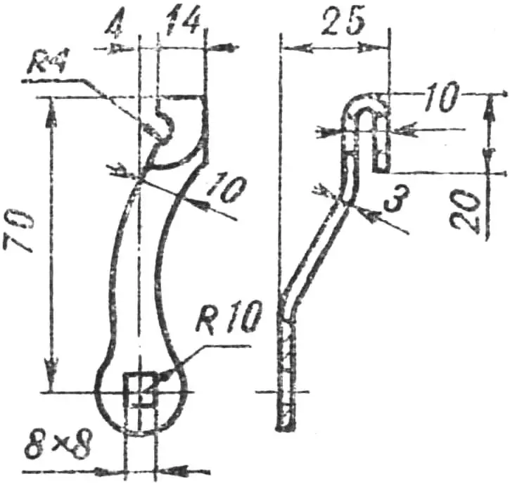
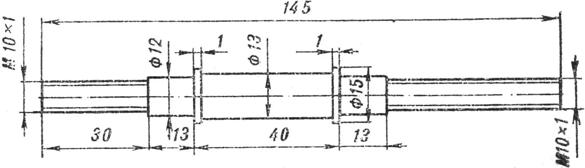
The front fork is telescopic, with spring shock absorbers. The fork bridge is turned on a lathe, then milled, and a hole is drilled and bored in it. The fork bridge axle, telescopic shock bodies, and fork leg tips are pressed into the bridge and soldered with brass. When assembling the fork legs, they are packed with grease.
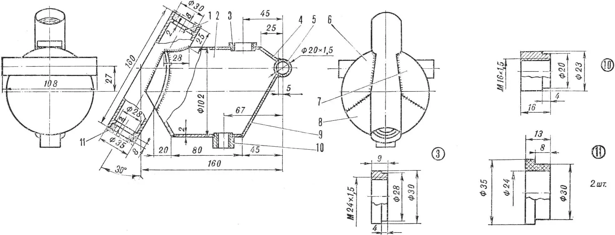
1 — frame head, 2 — tube (T102×1.5, l = 140), 3 — filler neck, 4 — plate, 5 — tube (T20×1.5, l = 108), 6–9 — plates, 10 — fitting, 11 — support bushing.
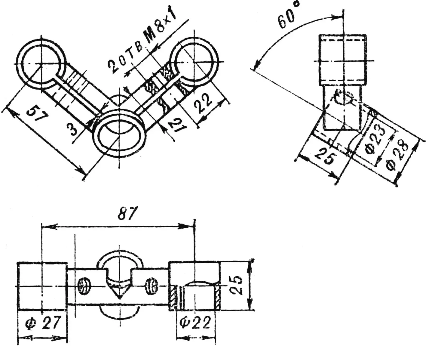
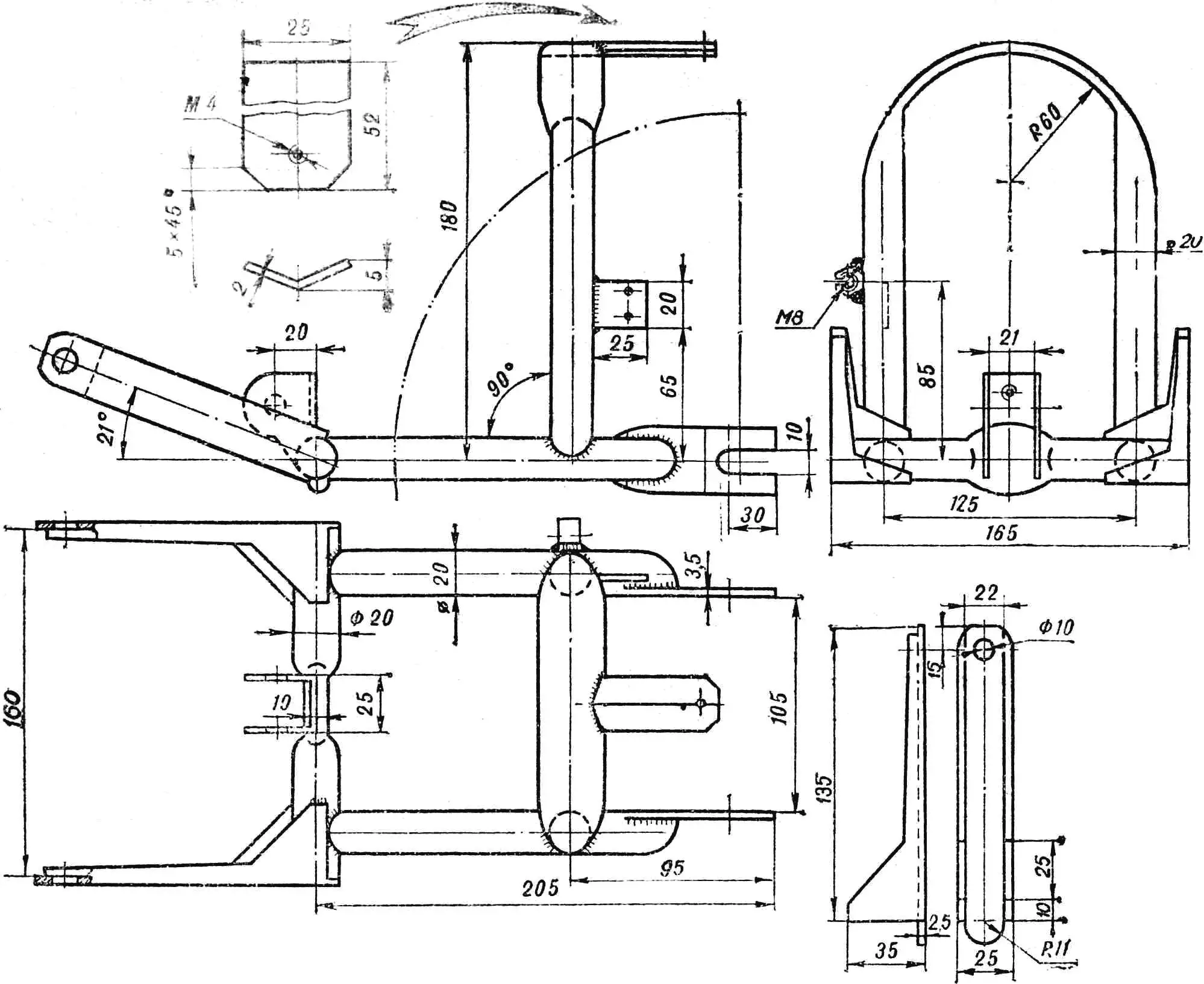
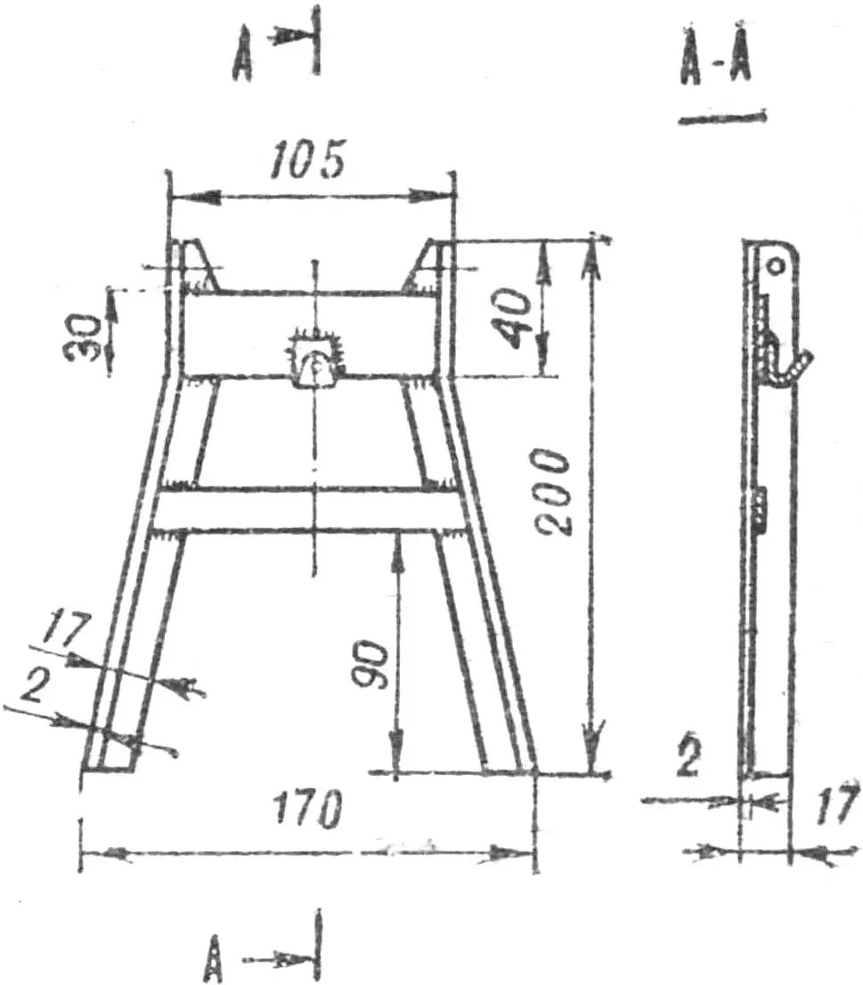
The swingarm of the rear suspension is also homemade. It is attached to the frame with two M8 bolts where the drive sprocket axle passes. The bolts must be strictly coaxial.
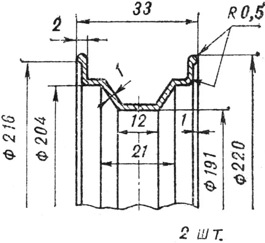
The wheels are designed for standard scooter tires. The rims are homemade, turned. The front wheel hub and spokes are bicycle parts, while the rear rim is connected to a homemade hub with eighteen spokes from a “Lviv” moped wheel.
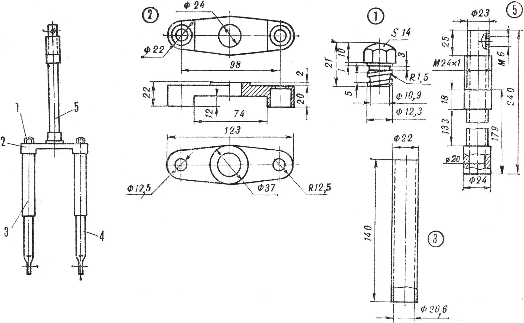
1 — bolt, 2 — fork bridge, 3 — shock absorber, 4 — fork leg, 5 — steering stem.
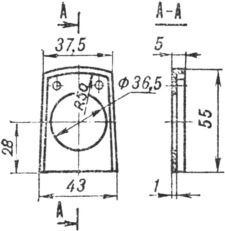
The brake drum and shoes are made of D16T aluminum alloy. Each shoe was turned on a lathe, then drilled and milled. Friction linings are riveted to the shoes thus made with aluminum wire.
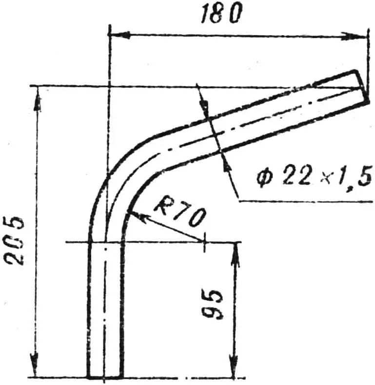
The exhaust pipe is assembled from the stock bend of a Sh-58 engine, an adapter bushing, and a muffler. The bend must be reworked — it should be bent as shown in the drawing.
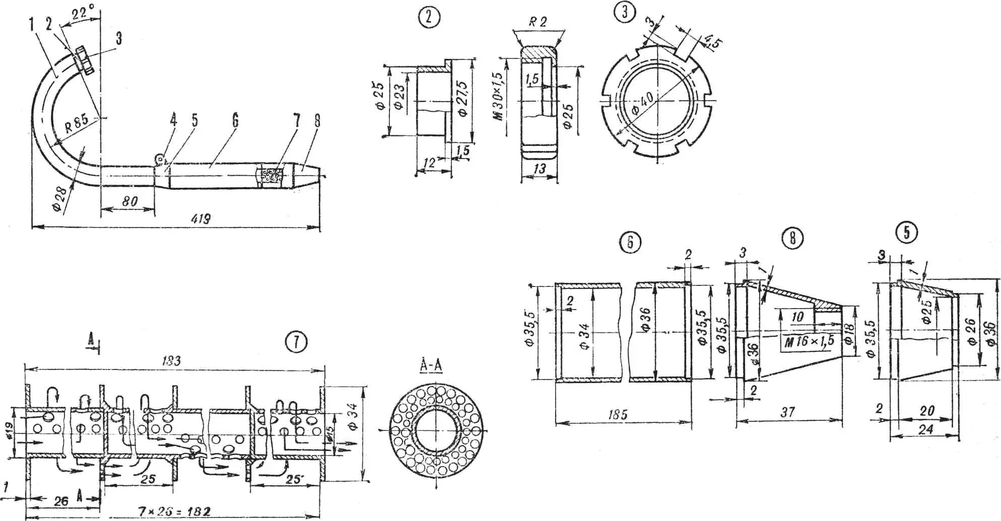
1 — bend, 2 — adapter bushing, 3 — nut, 4 — lug, 5 — cone, 6 — muffler tube, 7 — muffler insert, 8 — cone.
The motorcycle seat is made of sheet duralumin, foam, dense fabric, and black artificial leather.
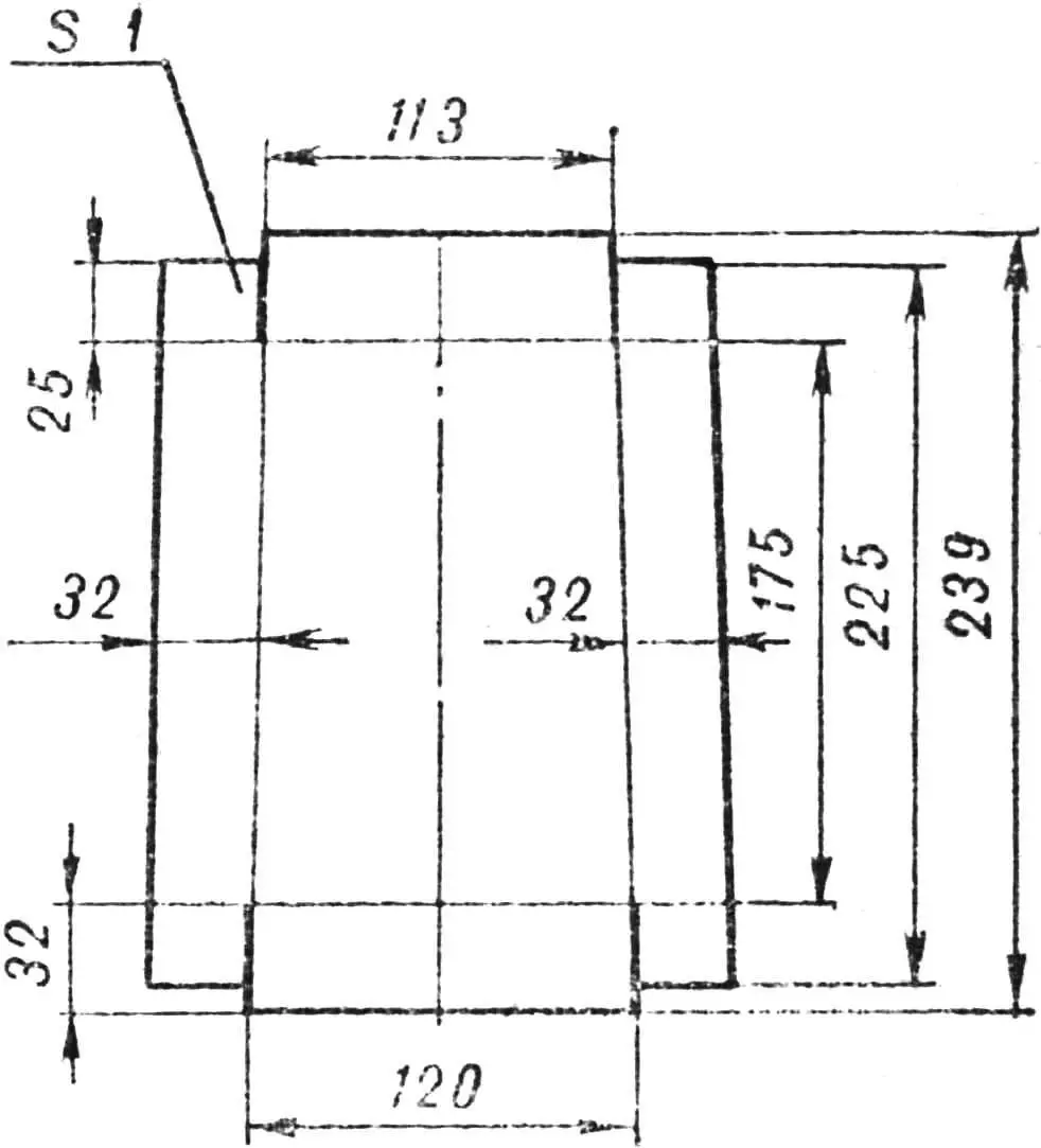
The tool box is hidden under the micromotorcycle seat. It is made of 1 mm sheet aluminum.
Painting the “Kuznechik.” After welding, the frame is cleaned thoroughly: rust, slag, and metal spatter are removed. Then it should be primed and only after that painted in several coats. The color depends on your resources and taste. I, for example, used black nitro enamel, and on the fuel tank I stencilled the silhouette of a grasshopper in white nitro paint. The exhaust pipe, fork legs, rear wheel hub, handlebar bridge, and rims are chrome-plated.
«M-K» 7’79, A. LYKOV
Recommend to read
 TRIUMPH: COMFORT PLUS SPEED
"They are not afraid of obstacles!" this is the motto of our magazine a few years ago began to publish descriptions of the designs of a homemade all-terrain of micro-technology,... THE ‘MOLE’ TO THE RESCUE
Aviation mechanic M.A. Masterov is one of that remarkable group of amateur designers that the Udmurt land has always been proud of. His achievements include such serious works as delta-...
