It is unlikely that among adults there will be a person who can remain indifferent to the appearance of a beautiful homemade car or motorcycle on the street. And what can we say about the boys, if just the opportunity to ride in such a car is happiness for them! And how often can you hear: “I wish I had one like that!”
That’s why Konstantin Antonovich Remez, head of the karting and design laboratory at the Slonim city station for young technicians in Belarus, decided to offer his students to build a micromotor scooter.
The group was selected without difficulty. It included ninth-graders Volodya Deyko, Volodya Nalivaiko, Sasha Shchulyak and seventh-graders Slava Vashkevich and Volodya Emelyanchik.
We figured out where to start. The wheels are only from the kart. This means that we need to make a motor scooter with a sidecar, since it is difficult to make turns on such wheels. There is also an engine, but a motorcycle one, without forced air cooling. This will have to be taken into account. There were no problems with materials, because the station is supervised by an auto repair company, and there, if you dig through the waste, you won’t find anything!..
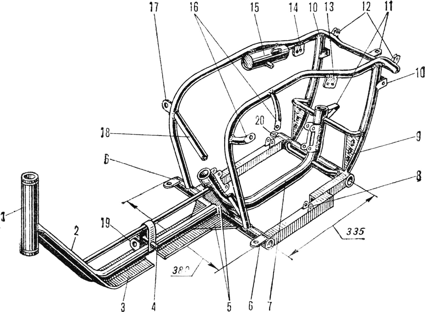
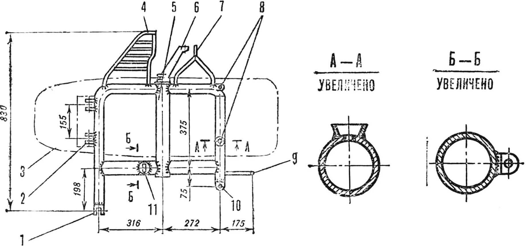
1 — steering column bushing, 2 — pipe, 3 — floor support, 4 — pedal axle, 5 — gussets, 6 — floor mounting hinges, 7 — sub-frame, 8 — hood holder, 9 — rear fork suspension unit, 10 — rear shock absorber mounting brackets, 11 — fender mounting hinges, 12 — brackets for the hood, 13 — fuel pump bracket, 14 — ignition coil bracket, 15 — supply tank, 16 — fan mounting tabs, 17 — sidecar traction bracket, 18 — strut, 19, 20 — sidecar suspension brackets.
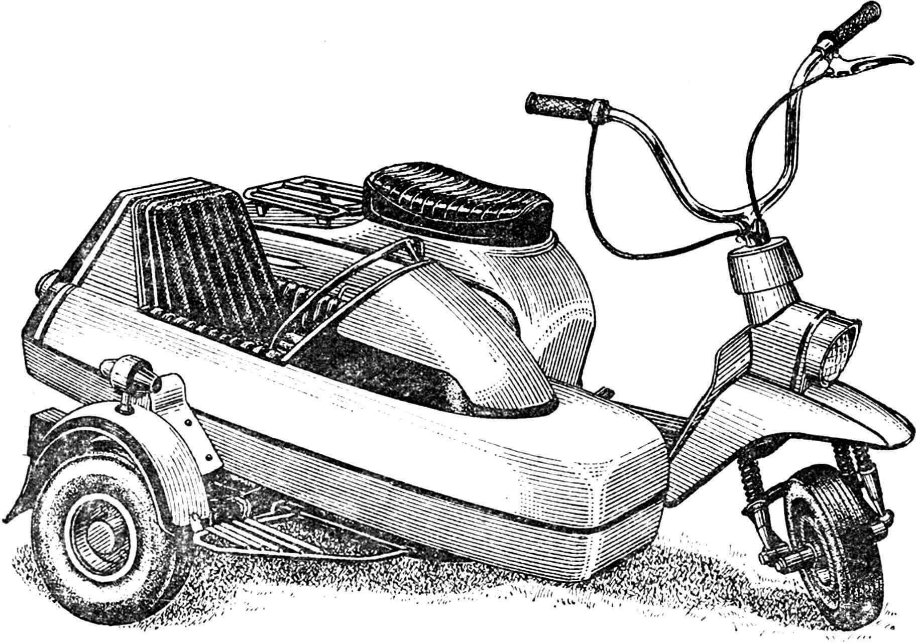
Soon the “Bug” – as the scooter was dubbed – was ready. The machine turned out to be very reliable in operation. She easily carried two people at a speed of 60 km/h, while consuming only 5 liters of fuel per 100 km of travel. In addition, the carefully thought-out layout and magnificent appearance have brought the scooter wide popularity. The very next year after its construction, it was exhibited at the USSR Exhibition of Economic Achievements in the “Young Technicians and Naturalists” pavilion.
How does the “Bug” work?
Its frame (Fig. 1) is welded from half-inch, inch and one-and-a-half inch steel pipes. In front there is a bushing for the steering column, in the center there is a sub-engine frame. Both of them are from the M-105 motorcycle. The sub-engine frame is reinforced with transverse pipes and gussets with holes in which the pendulum fork from the Izh-56 motorcycle, only shortened by 120 mm, is suspended (Fig. 2). It has short, cantilevered axles for shock absorber heads from the M-106.

1 — suspension bushing, 2 — brake disc torque rod fastening loop, 3 — axles for shock absorber heads, 4 — chain tension screw stops.
The rear fender is taken from the same motorcycle and shortened. The front wing was cut from an old Zhiguli body. The socket for the headlight from the Verkhovyna moped was also made from a 0.8 mm sheet.
The steering wheel is curved from a Ø 22 mm pipe and chromed.
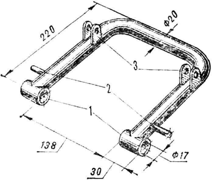
1 — support bushings, 2 — axles for shock absorber heads, 3 — hinges for connecting to the fork.
The front pendulum fork (Fig. 3) is homemade. Shock absorbers from Verkhovyna with rods shortened by 40 mm are attached to it.
The hood is from a Vyatka scooter, cut off, narrowed, and elongated in some places, for example in the front, so that the cylinder head does not rest against it. (They pulled it out with a nylon hammer on a nylon plate.) The trunk on the hood is from the M-106, the rear light is from the Java-634. In front of the hood, on the floor, there are homemade brake pedals and a double-arm gear shift lever. But on the steering wheel there are motorcycle controls: the gas handle is from the M-105, the clutch is from the Voskhod.
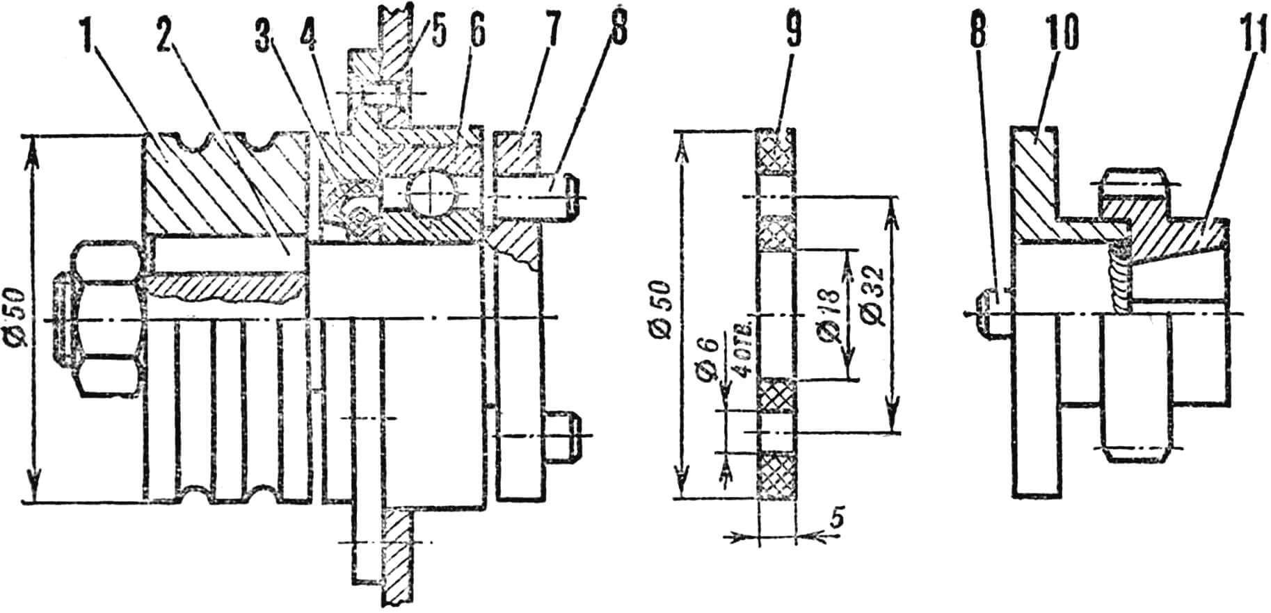
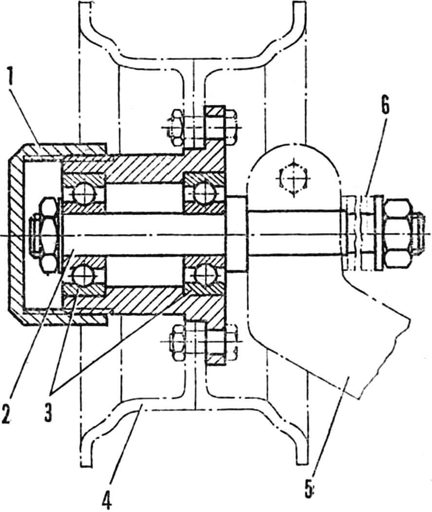
1 – drive pulley, 2 – key, 3 – cuff, 4 – housing, 5 – gearbox wall, 6 – bearing No. 204, 7 – left coupling half disk with shaft, 8 – pins (4 pcs.), 9 – textolite washer, 10 – right coupling half, 11 – gearbox gear.
The engine is entirely from M-105. Since the cylinder head is located under the hood, its cooling conditions are different than on a motorcycle. Therefore, a fan was needed to forcibly remove excess heat from the head. To do this, a fan drive coupling half was welded to the small drive gear of the gearbox. Another coupling half with a shaft and bearings was installed in the wall of the box body. A drive pulley is attached to the outer end of the shaft. Two belts (o-rings of a tractor engine) connected it to the driven pulley located above, on the shaft of which there is a duralumin fan impeller – just opposite the cylinder head. In order for its fins to cool better, it is rotated 90° to the right (this does not affect the operation of the cylinder). Exhaust gases are discharged through an exhaust pipe and muffler taken from the M-105 motorcycle. Like many other parts, they are shortened in place.

1 – driven pulley, 2 – shaft, 3 – bearings No. 201, 4 – housing, 5 – impeller (on the left is its blank).
The ignition and engine control systems are left unchanged. Only the gear shift pedal, placed forward on the floor in front of the hood, is connected to the gearbox with a rod made of a Ø 16 mm pipe.
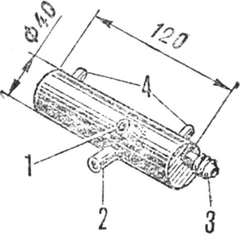
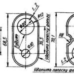
1 – fitting “from the pump”, 2 – fitting “to the carburetor”, 3 – fitting for draining excess fuel into the tank, 4 – bosses for fastening.
Fuel is supplied to the carburetor by a vacuum pump from the Whirlwind outboard motor. A vacuum is created in the engine purge channel, into which a fitting is screwed, connected by a hose to the pump diaphragm. From it, fuel flows into the supply tank (Fig. 6), located on the frame. Fuel goes from the tank to the carburetor, and the excess is drained back into the tank.
1, 10 — mounting brackets for the scooter, 2 — front support of the cradle, 3 — cradle, 4 — footrest, 5 — pipe with torsion bar, 6 — wheel suspension arm, 7 — axle under the upper head of the wheel shock absorber, 8 — spring supports, 9 — muffler mounting bracket, 11 — sidecar traction mounting ear.
The stroller frame (Fig. 7) is welded from inch steel pipes and is attached to the scooter frame at three points. One of them is a rod – a piece of pipe, into the ends of which M18X1.5 nuts are embedded and eyebolts are screwed in. Half of the front wheel suspension of the SZA motorized stroller is welded into the middle of the frame. The elastic element here is a torsion bar passed through the pipe. One end of it has a suspension arm, the other is sealed.
The stroller’s cradle contacts the frame with a front support and two coil springs at the rear. The front support ears with the forks on the frame are connected through conical rubber bushings with bolts. The cradle body is made from four front and four rear wings of an old Zhiguli body. The fairing is from the front hood of a SZA motorized stroller. The parts were connected by beading the edges using gas welding. Then they cleaned, primed, puttyed and painted. The seats in both the cradle and the scooter were converted from Moskvich-412 seats.
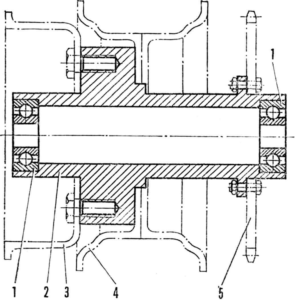
1 – axle, 2 – bearings No. 202, 3 – hub, 4 – wheel disk, 5 – support bushing for the pendulum fork, 6 – shock absorber head.
Behind the seat in the cradle there is a fuel tank measuring 320X200X80 mm with a capacity of five liters. Its neck from the Moskvich-408 is placed on the back wall of the cradle and closed with a lid. Fuel goes to the pump and back from the supply tank through two gas-resistant hoses.
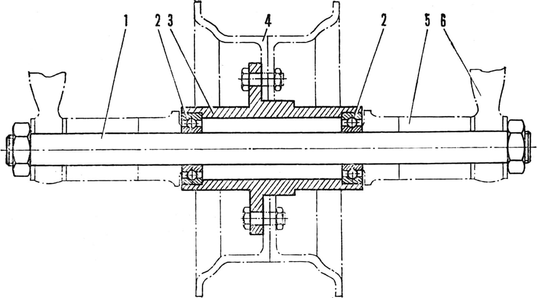
The wheels of the “Bug,” as already mentioned, are from a kart. All axles and hubs (Fig. 8, 9 and 10) are steel, turned on a lathe.
1 — bearings No. 203, 2 — hub, 3 — brake drum, 4 — wheel disk, 5 — sprocket.
The steering wheel suspension is simple. Unless the steering fork is connected to the pendulum through rubber bushings and shock absorbers.
The suspension of the rear, drive wheel is much more complex. Its axis can move in the grooves of the pendulum fork with screws that tension the chain from the M-104 motorcycle. A sprocket from “Verkhovyna” is screwed to the right of the hub, and a brake drum from “Vyatka” is screwed to the left.
1 — plug, 2 — axle, 3 — bearings No. 203, 4 — wheel disk, 5 — suspension arm, 6 — shock absorber head.
The wheel suspension of the trailer stroller has already been half considered. It remains to add that, in addition to the torsion bar, there is also a shock absorber from the Voskhod motorcycle. The lower end of the torsion bar is fixed on the wheel axis, the upper end on a special axis, placed on an L-shaped stand 90 mm above the plane of the stroller frame.
Recommend to read
 UNIVERSAL BATTERY
At work and in everyday life there is often a need in galvanic power source with a stepped gradation of the EMF (including the symmetric polar voltage). Often this "standard" range:...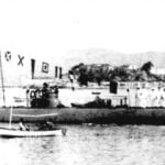 THE APENNINES AT THE START
Included in the First world war later than the other great (or applying for this role) powers, Italy was behind them in many branches of naval Affairs. And probably not due to a lack of...
