Each of the plugs is welded oneplace the levers of rotary fists of steering system assembled on welding of the steel strips section mm. 5X25 and some Of them are manufactured and the transverse thrust; in the zones of location of the holes (in the middle and on the ends) welded to a short l-shaped segments of the same steel strip. Fists and transverse thrust pivotally connected with threaded bolts M12 washers, nuts and lock nuts.
To the Central steering shaft (steel tube Ø 27X2,5 mm) from the bottom steering arm is welded, assembled from steel strips and 5X25 5X30 mm and a sleeve made of steel pipe Ø 34х3 5 mm, a length of about 40 mm. In three places to the hub podvalivaet flare nut from the Bicycle fork bearing, the inner diameter of which is dispersed to 27 mm. the Steering shaft is inserted from below into the steering column to the cross beam. Column is a segment of pipe Ø 34X3. 5 mm from the groove at a site 20 mm Ø 32,7 mm, inserted into the steering column of the frame of the motorcycle. Connection — welding, using steel strip 5X25 mm section and a length of about 70 mm. from the Top to the steering column of the frame of the motorcycle press-fitted bushing Ø 34X3. 5 mm, the machined top under the bearing Cup of the steering column of Bicycle forks. The same Cup mounted on the steering column cross beam and bottom.
The Central steering shaft connects to the wheel using a flange — plate steel section 7Х45 mm and a length of 90 mm with hole Ø 10 mm for brackets steering, which preparine to the sleeve from Ø pipe 34X3,5 mm. From the opposite side bushing tapped М34Х1 mm, and it tightened the lock nut and nut. For the past three welding points is attached to the cone nut Bicycle fork bearing, the inner diameter of which is dispersed to 27 mm. To the Central steering shaft bushing along with welded to it a flange is secured with two threaded bolts M8 nuts and washers through the holes in the sleeve and steering shaft.
The engine of my motocicle — motorbikes M-105. Given the fact that the fuel tank is relatively low, in the carburetor of the engine of the regular cover of the float chamber replaced with the cover from the float chamber of the motor scooter Elektron — fitting it is horizontal.
Pedal shift lever trimmed by 25 mm in order not to interfere with the transfer to motociclo with wheelchairs.
All control motociclon, of course, manual. Manual and starter. It consists of a handle, a small lever and the connecting strap. The starting handle is a section of steel pipe Ø 22 mm, bent in accordance with the shape of the seat. At one end is welded a threaded bolt M10, serving as the axis of the handle; on the other stretched the plastic cover from the handle of a Bicycle wheel.
The lever is hinged in the sleeve that is welded to the bracket of the seat back.
The adapter is attached to the lever, motorcycle kick-starter, has the form of half of a donut; he bent from the reinforcing bar Ø 12 mm, after which it is welded steel strip section 5X30 mm and 5X25 mm. On the lever kick starter adapter is fastened using brackets, bent from a reinforcing bar Ø 6 mm, bolt M8. The starting handle and the adapter are connected to a solid belt, however, instead of a belt it is possible to use steel cable.
It should be noted that more interesting is the starter with the sprocket mounted on the shaft kick-starter is driven in rotation Volochkovoj chain, which, in turn, connects with the crank. The asterisk for this purpose it is suitable from kids bike (its outer diameter needs to be 120-150 mm).
Shifting engine matarrese also produced manually. The shift lever is located under the right hand of the driver under the steering wheel. He arched steel rod Ø 12 mm. On one of its ends secured plastic cher-arm, is welded to the other axis (the cut rod Ø 10 mm). The axle is fixed in the hole of the upper part of the frame of the motorcycle near the steering column. On the free end of the lever fits over a bushing with welded thereto a small lever (steel strip 5X25 mm) and fixed on an axis using three screws with M6 thread.
The lower part of the gearshift mechanism is a fork, curved from rod Ø 12 mm, which is welded to the lever, having the ability to turn on the axis. In the mouth plug part of the pedal is normal gear; turn the lever (and therefore the plugs) included one or the other gear. The lower and upper levers gear shift is connected by a rod, made of steel rod Ø 8 mm.
The rear brakes are also manual, with a lever made from steel strips with a cross-section and 5X25 5X30 mm. On the upper end of the lever is mounted a rubber grip from a motorcycle handlebar, and the bottom bolt is fixed on the regular brake pedal. The rod connecting the brake lever and the lever on the hub of the rear wheel matarrese, of curved reinforcing rod Ø 6 mm. There on my motor vehicle and the front brake — but only on the right wheel. During operation of the machine was that the use often have a front brake, because when braking the rear you have to remove the right hand from the steering wheel, and it is difficult to manage motociclo. More convenient to have the drive of the brake mechanism of the rear wheels by a cable and lever on the handlebars, the type of front. To do this, in principle, even simpler than using leverage.
The wheel matarrese curb the type of the motorcycle: on the right — handle of the throttle of the carb and the front brake lever, left — handed clutch control. Left side steering also sets the lever of a drive of the decompressor.
Fig. 1. The basic version of the motorized vehicle with manual control:
1 — soft hood bonnet, 2 — wheel, 3 — rotary armrest, 4 — motor M-105, 5 — seat, 6 — adjustable backrest, 7 — passenger seat, 8 — frame motorcycle M-106, 9 — soft step, 10 — front wheel (from scooter “Tourist”), 11 — cross, 12 — front fork, 13 — rear wheel (motorcycle M-106).
Fig. 2. Front fork:
1 — shaft front fork, 2 — ring bearing, 3 spacer (fork road bike), 4 — feathers plugs (pipe Ø 27 x2,5 mm), 5 — clamp bracket (steel strip 5×25 mm), 6 — pin (steel strip 5×25 mm), 7 — hinge steering lever, 8 — washer, 9 — steering arm (welded from steel strips 5×25 mm).
Fig. 3. Steering shaft:
1 —flange (steel strip 7×45 mm), 2 — bolts-clamps M8, 3 — sleeve with external thread М34х1 mm, 4 — lock nut 5 — nut, 6 — shaft (steel tube Ø 27×2,5 mm), 7 — ring bearings, 8 — bushing-adapter (steel pipe Ø 34×3. 5 mm), 9 — steering arm (welded from strips and 5×25 5×30).
Fig. 4. The transverse beam of the frame:
1 — steering columns, front forks (steel tube Ø 34Х3,5 mm), 2 — sleepers (steel tube Ø 27Х2,5 mm), 3 — column steering shaft (steel tube Ø 34Х3,5 mm), 4 — Cup bearings (Bicycle frame), 5 — sleeve, 6 — struts.
Fig. 5. The starter with an asterisk:
1 — the lever of the starting device (tube Ø 22×2. 5 mm), 2 — chain retainer, 3 — Bush roller chain (Bicycle), 4 — star (from a child’s Bicycle), 5 — staff, the lever of the starting device of the engine, a 6 — bolt with nuts, 7 — plate (steel strip 5h30 mm), 8 — spring, 9 — clamp circuit.
Fig. 6. The seat back frame:
1 — hinge (steel strip 4×20 mm), 2 — lock (steel strip 5×30 mm), 3 — bracket (steel strip 4×20 mm), 4 — the base (steel tube Ø 18×2,5 mm), 5 — cross member (steel strip 5×25 mm), 6 — bracket (steel strip 5×25 mm), 7 — lower cross member (steel strip 5×25 mm) 8 — bracket (steel strip 5×25 mm), 9 — bracket (steel strip 4×20 mm).
Fig. 7. Armrest:
1 — hinge (steel stud M12), 2 — base (area 20x20x4 mm) 3 — screws 4 — wooden base (bar 20×30 mm) 5 — filling (cotton or felt), 6 — screw 7 — trim (leatherette).
Fig. 8. Seat back:
1 — peg, 2 — mounting brackets 3 — frame (wooden bars 30×35 mm), 4 — trim (leatherette), 5 — mounting brackets 6 — plywood base (plywood thickness of 4 mm), 7 — filling (felted or felt), 8 — fill (foam rubber 50 mm thick), 9 — a covering (artificial leather).
Fig. 9. The seat base:
1 — bracket (steel strip 4×20 mm), 2 — cross member (steel strip 5×25 mm), 3 — a longitudinal element (steel tube Ø 22×2. 5 mm), 4 — cross member (steel tube Ø 22 x 2,5 mm), 5 adaptor (steel strip 6×40 mm), 6 — longitudinal element (steel area 20x20x4 mm), 7 — ring (steel wire Ø 6 mm), 8 — bracket (steel strip 5×25 mm), 9, 11 — brackets (steel strip 5×25 mm) 10 — castle (steel wire Ø 6 mm).
Fig. 10. The driver’s seat:
1 — cushion (foam thickness of 50 mm), 2 — gasket (foam rubber 50 mm thick), 3 — the bottom of the cushion (felt or felt with a thickness of 20…30 mm), 4 — a plywood sub-floor (plywood thickness of 4 mm), 5 — seat base (wood 20×30 mm), 6 — clip-retainer (wire Ø 1,5 mm), 7 — the screw of fastening of a seat, 8 — medical rubber circle. No. 2 9 — the covering (artificial leather).
Fig. 11. The trunk:
1 — base (rod Ø 10 mm) 2 — front (steel strip 5×30 mm), 3 — brace (steel strip 5×25 mm), 4 — clip (steel wire Ø 6 mm), 5 — cross member (steel strip 4×20 mm), 6 — clip (steel wire Ø 6 mm), 7 — front cross member (steel strip 5×25 mm).
Fig. 12. Removable passenger seat:
1 — covering (artificial leather), 2 — cushion (foam thickness of 50 mm), 3 — shim (felted or felt), 4 — base (plywood thickness of 4 mm), 5 — nail 6 — base (block 20×30 mm), 7 — pin (steel strip 4×20 mm), 8 — screws 9 — lock (steel strip 5×30 mm), 10 — clip (steel wire Ø 1,5 mm), 11, 12 — flanges (steel strip 4×20 mm).
Fig. 13. The lever of the starting device of the engine:
1 — crank (bike handlebar), 2 — lever (steel tube Ø 22×2. 5 mm), 3 — bracket (steel strip 5×25 mm), 4 — arm shaft (bolt M10).
Fig. 14. Adapter starting device:
1 — arc (steel rod Ø 12 mm), 2 — flange (steel strip 5×30 mm), 3 — tie (steel rod Ø 8 mm).
Fig. 15. Brake lever:
1 — stick, 2 — lever (steel strip 5×30 mm), 3 — earring (steel strip 5×25 mm), 4 — bracket (steel strip 5×30 mm).
Fig. 16. Tie rod:
1, 3 — lining (steel strip 5×25 mm), 2 — the reinforcement (steel rod Ø 10 mm) 4 — cross member (steel strip 5×25 mm), 5 — plate (steel strip 5×25 mm).
Fig. 17. Soft bonnet:
1 — covering (artificial leather), 2 — cushion (foam thickness of 50 mm), 3 — spacer (felt or felted), 4 — a plywood sub-floor (plywood 5 mm thick), 5 — base (wood 20×30 mm), 6 — shackle spring (wire Ø 2.5 mm).
Fig. 18. The basis of soft bonnet (welded from steel strips with a cross-section 4X20, and 5X25 mm).
Fig. 19. A soft footstep:
1 — covering (artificial leather), 2 — cushion (foam thickness of 50 mm), 3 — spacer (felt or felted), 4 — a plywood sub-floor (plywood 5 mm thick), 5 — base (wood 20×30 mm), 6 nails, 7 screws attaching the foot pegs.
Fig. 20. The base of the pegs (welded from steel strips with a cross-section 4×20, and 5×25 mm).
Landing on motociclo produced with wheelchairs (I have, incidentally, is also altered — I installed it on the shock absorbers and replaced the little rear wheel on one Central, larger diameter, borrowed from the old children’s bike). To do this, of course, is not so easy, but not so difficult to become an obstacle to drive motocicle. After landing, the wheelchair is rolled back beyond the wheels matarrese, and I go to reverse out of the garage due to the slope of the floor of the garage toward the gate. By the way, now I’m working on a mechanism of a manual drive wheelchair, allows you to move it backwards.
On my motocicle on a good road you can drive at speeds up to 90 km/h, but faster than 60 km/h to drive risky. On turns or roads with lateral incline of the chair is not too stable (especially with a passenger!), since the center of gravity of the motor means is high and also shifted back. It is therefore now working on a new version motocikla — installed rear two wheels of the scooter “Electron” instead of one of the motorcycle M-105. The optimal distance between the wheels of the rear axle — 450 mm. wheel Suspension requires independent. The axles of the wheels will move backward 80 mm (this will also increase the resistance), and the back seat will be below 140…150 mm. the Diagram of this option matarrese shown in my drawing.
In addition to the basic and improved version, I draw two more layout, more comfortable, sustainable and at the same time simple to manufacture. I believe they will also attract the attention of the interested in this form of transport readers. Most interesting I think is the last option.
Fig. 21. An improved version motociclo. The main difference from the first option — the use of independent suspension of the rear wheels of smaller diameter (of the scooter “Electron”).
Changed and chain transmission — it includes a block of intermediate stars. On the intermediate shaft is also disc brake. The front part motorela is almost the same as in the first embodiment.
Fig. 22. The third option motociclo. Frame — a homemade, welded corners and pipes. Tricycle scheme with front steering wheel has a high resistance. Rear pendular axle has the shock absorbers of the motorcycle M-105. Wheels from scooter “Tourist”. Transmission has an intermediate block of stars. The engine-driven only on the right rear wheel.
Fig. 23. Universal motociclo (fourth edition). It is the most stable, the most technologically advanced to manufacture in a controlled environment. To increase the stability and simplify the engine is mounted on the pendulous fork.
And the third and fourth option are the leading matarrese only the rear right wheel, which saves the structure from heavy and expensive differential. The drive from the engine to the driving wheel is implemented using a two-stage chain transmission with an intermediate shaft.
It should be noted that the size of the driver’s seat, backless padded hood and armrests in all variants the same, and, if there are willing to repeat my designs, I can assure you that the size of their well-proven in practice and completely acceptable for many spinal patients.
Any of the four variants can be equipped with manual drive (front and rear), the design of which is depicted in my drawing. This drive allows, if necessary (for example, engine failure) to move at a speed of 2…5 km/h and also helps to turn around in a narrow space or file ago.
That’s all about my work. In his experience, know very well how spinal patients need to be lightweight, maneuverable and easy to fit and comfortable, reliable operation compact and powerful enough vehicle. Unfortunately, the industry does not produce such. Of course, there are motorized wheelchairs Serpukhov plant, and “the Cossacks” with manual control. But they, unfortunately, do not meet many requirements of people who have lost mobility. If it is light, maneuverable and cheap means of transport was mass-produced, I think it would be able to find a huge demand and were able to significantly improve the difficult life and “disabled people in wheelchairs”, and many other bad moving non-ambulant or disabled.
E. FEOFILAKTOV, settlement NEMA, Kirov.
Recommend to read ECONOMICAL PN-70 As a stand-alone power source flash FIL-46 I use a voltage Converter PN-70, manufactured by Kharkiv enterprises "ECHO". In the process of operation of this device revealed its drawback:... REZINOMOTORNAYA HELICOPTER The model we offer you to make, made by rare scheme — two bearing rotor during rotation intersect. To build it is not very difficult — especially as the engine are well-known modelers... 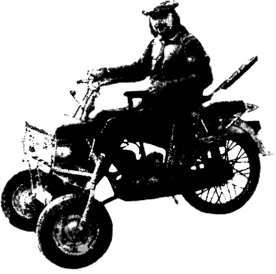
 First a few words about yourself and a situation in which I found myself by fate. It all started with the fact that at the time of the motorcycle accident I received a severe spinal injury with spinal cord injury. Unfortunately, I did not immediately, but two months after the injury. In the end, total paralysis of the body from the shoulder blades and down to the heels. The rest of my life I was destined to spend in bed or in a wheelchair. And I was, when I broke down, only 26…