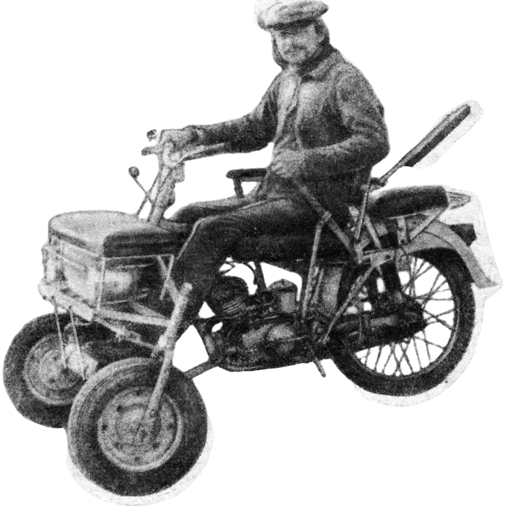
First, a few words about myself and the situation fate put me in. It all started when, during a motorcycle accident, I suffered a severe spinal injury with damage to the spinal cord. Unfortunately, I was not operated on immediately, but two months after the injury. The result was complete paralysis of the body, from the shoulder blades down to the heels. I was destined to spend the rest of my life in bed or in a wheelchair. And when I “broke,” I was only 26…
I could not resign myself to immobility; I even learned to use a wheelchair. But you can’t go farther than the gate in one: try it yourself — and on our potholes!
At first I hoped I could buy a Zaporozhets with hand controls, but unfortunately that proved practically impossible: a huge queue at the regional social-security office, and the cost… The only thing left for me was to make a reliable and simple vehicle for myself. So, to make life easier, I decided to build a motor chair — one suitable for every occasion: a trip to the store, a visit to friends, and an outing into nature — to listen to the birds and breathe some fresh air.
I assessed my physical condition quite soberly and knew that assembling a motor chair would not be easy for me. Therefore, already at the design stage I aimed for the simplest possible technology.
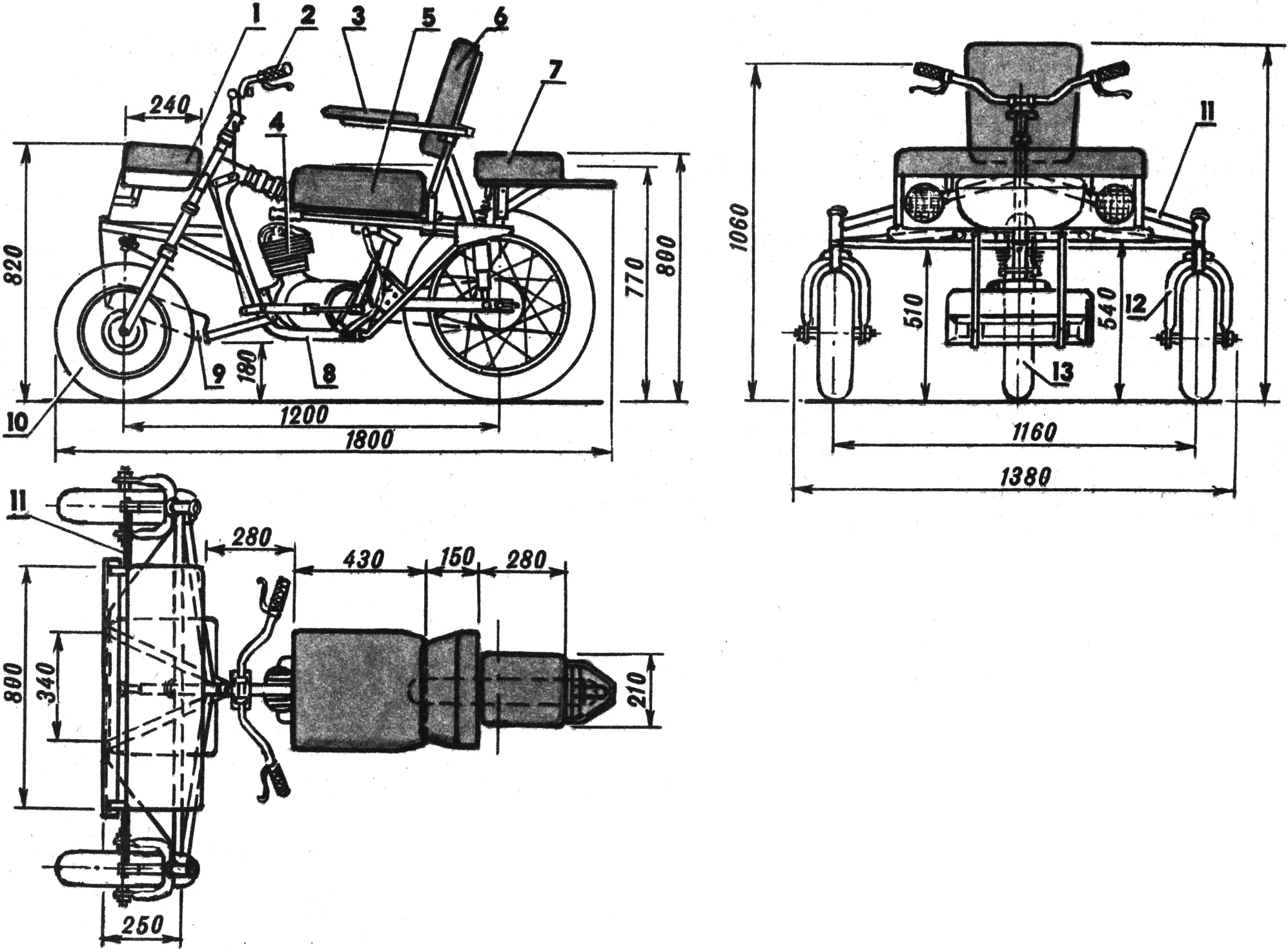
1 — soft hood, 2 — handlebar, 3 — pivoting armrest, 4 — M-105-type engine, 5 — seat, 6 — adjustable backrest, 7 — passenger seat, 8 — M-106 motorcycle frame, 9 — soft footrest, 10 — front wheel (from a Turist scooter), 11 — crossmember, 12 — front fork, 13 — rear wheel (from an M-106 motorcycle).
The basis of my design was a light Minsk M-106 motorcycle, so the layout of my motor vehicle turned out close to its layout. I developed the motor-chair design myself, but I could not fully fabricate it alone: my older brother Alexei, my friends, and most of all Viktor Chirkov, a fitter by trade, gave me a great deal of help. Nevertheless, I still made many parts myself, including the driver’s seat, its backrest, the hood, the footrest, and other items. All in all it took almost a whole year, but in the end I got a design that quite satisfied me in its parameters.
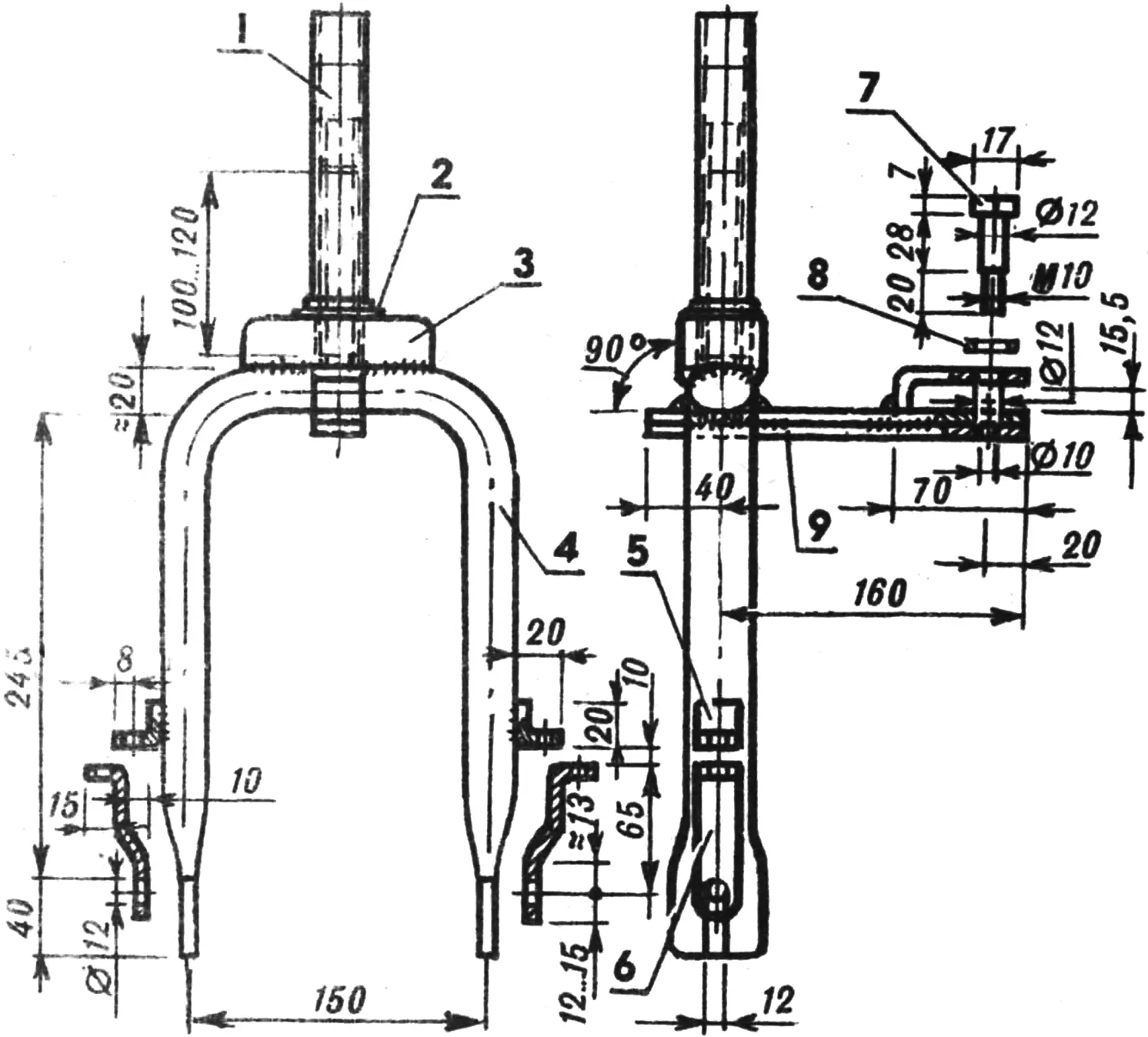
1 — front-fork shaft, 2 — thrust-bearing ring, 3 — spacer (from a road-bicycle fork), 4 — fork legs (Ø 27×2.5 mm tube), 5 — lock bracket (5×25 mm steel strip), 6 — lock (5×25 mm steel strip), 7 — steering-lever pivot, 8 — washer, 9 — steering lever (welded from 5×25 mm steel strips).
My motorized chair is arranged as follows. Its basis is an M-106 motorcycle frame: a transverse beam with steering columns for the wheel forks is welded to the front part. A front bumper — a length of 30×30×4 mm steel angle — is welded to the beam by means of braces made from tubes with an outside diameter of 22 mm and a 5×25 mm steel strip. In turn, the base of the soft hood, made from 5×25 and 4×20 mm strips, is attached to the beam and bumper. The hood itself is mounted on the frame with hinges and is held by a spring.
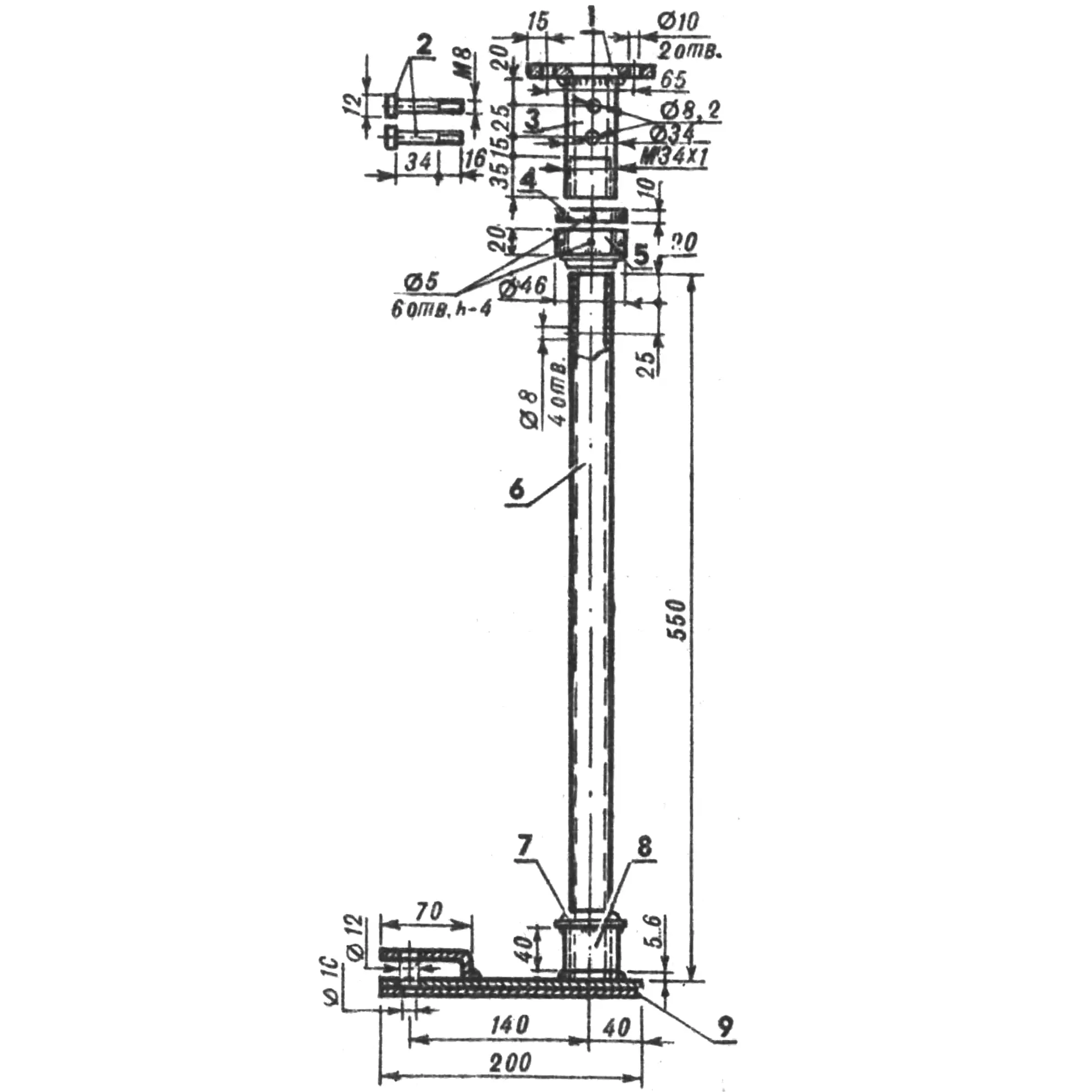
1 — flange (7×45 mm steel strip), 2 — M8 locking bolts, 3 — bushing with M34×1 mm external thread, 4 — locknut, 5 — nut, 6 — shaft (Ø27×2.5 mm steel tube), 7 — thrust-bearing rings, 8 — adapter bushing (Ø 34×3.5 mm steel tube), 9 — steering lever (welded from 5×25 and 5×30 strips).
Under the hood is a 10-liter fuel tank from an Elektron scooter; to the right and left of the tank are headlights from a Riga-type moped.
The soft hood, the driver’s footrest, the driver’s seat with backrest, and the passenger seat are all assembled from wooden bars, plywood, felt, foam rubber, and artificial leather. The driver’s seat has a distinctive design: an inflatable rubber medical ring with an outside diameter of 360 mm is built into it. Its use is dictated by the peculiarities of my physical condition: in spinal patients, trophism is impaired, and the muscles practically do not work — they do not spring.
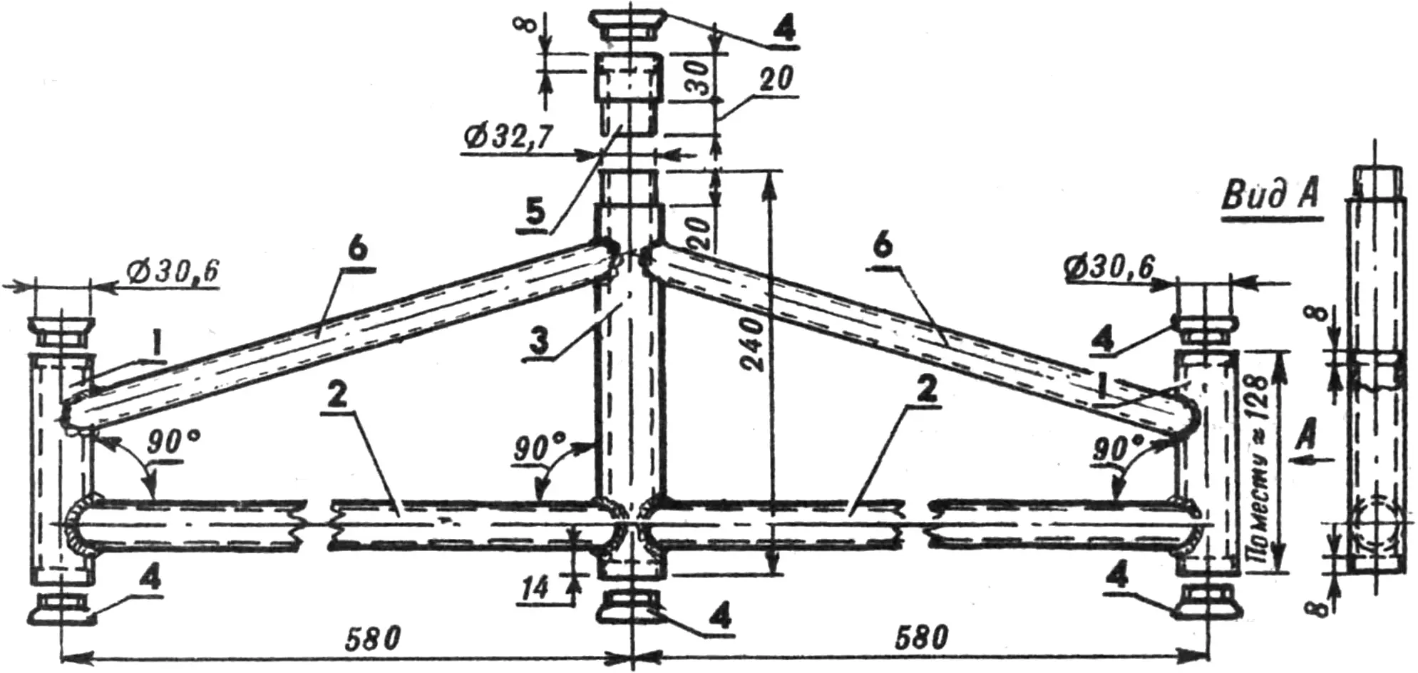
1 — steering columns of the front forks (Ø34×3.5 mm steel tube), 2 — crossmembers (Ø27×2.5 mm steel tube), 3 — steering-shaft column (Ø34×3.5 mm steel tube), 4 — bearing cups (from a bicycle frame), 5 — bushing, 6 — braces.
The driver’s seat backrest can fold back; the passenger seat is easily removed and mates with the backrest to form a kind of headrest. This is done so that one can stop periodically and rest; the legs then rest on the soft hood, and the body takes a comfortable, nearly horizontal position. The point is that for spinal patients the ability to change body position is of enormous importance, because it rests previously loaded areas of the body. All this helps avoid stagnation. Incidentally, for the same reason both the hood and the footrest are made soft.
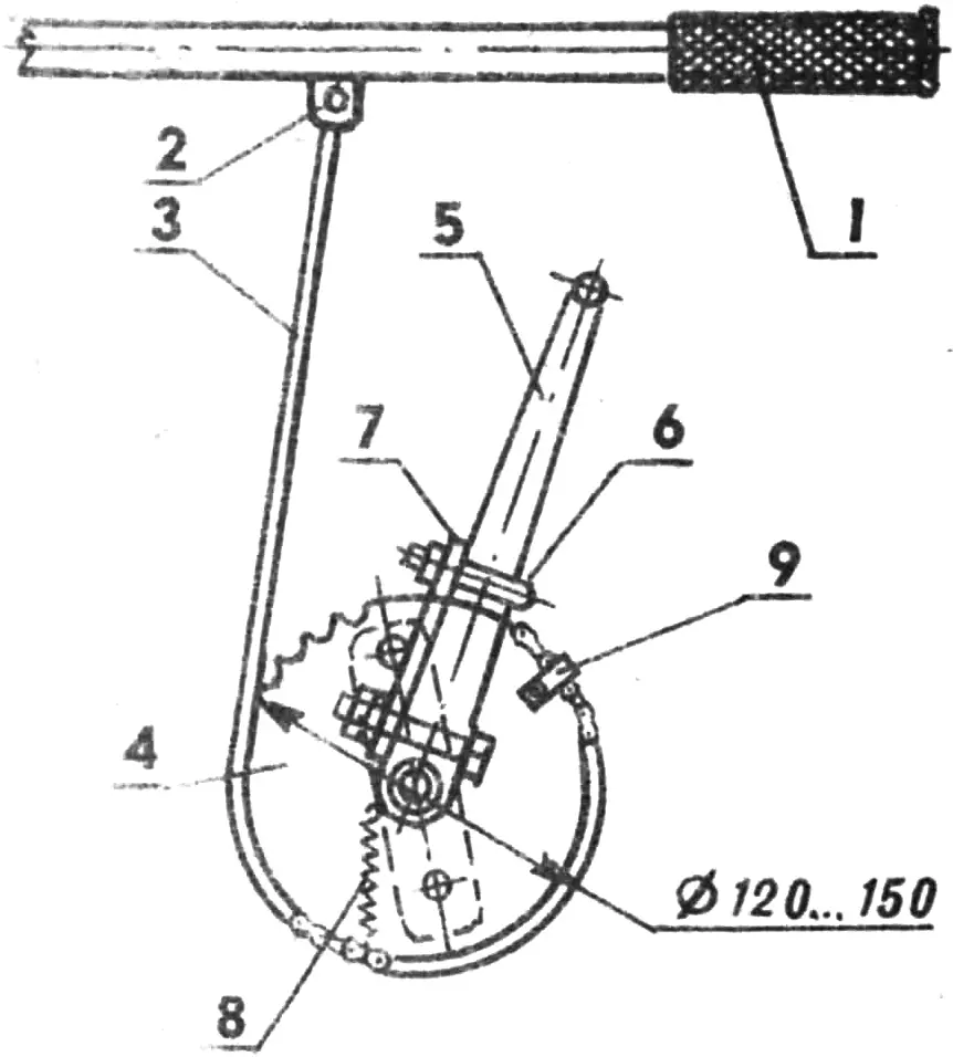
1 — starting-device lever (Ø22×2.5 mm tube), 2 — chain lock, 3 — bushing-roller chain (from a bicycle), 4 — sprocket (from a children’s bicycle), 5 — stock engine kick-starter lever, 6 — clamp with nuts, 7 — plate (5×30 mm steel strip), 8 — spring, 9 — chain attachment clamp.
The driver’s seat armrests fold away — they do not interfere with transferring onto the motor chair from a wheelchair; moreover, with an armrest folded back it is convenient to start the engine with the left hand. And in the reclining position the armrests keep the driver from falling out of the chair.
The driver’s seat is adjustable — it can move forward and backward by 60 mm and also change its tilt angle within small limits, making it possible to take the most comfortable position when riding. It is locked by means of a double comb made from a 5×25 mm steel strip.
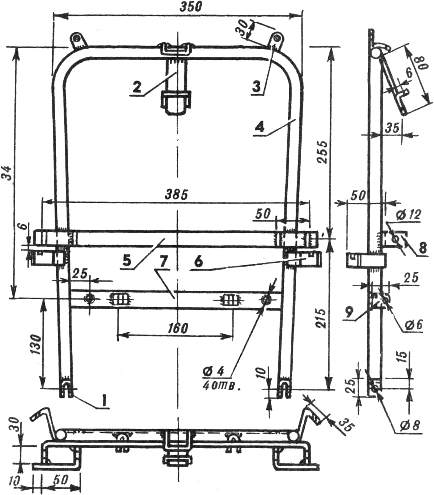
1 — hinge (4×20 mm steel strip), 2 — lock (5×30 mm steel strip), 3 — bracket (4×20 mm steel strip), 4 — base (Ø18×2.5 mm steel tube), 5 — crossmember (5×25 mm steel strip), 6 — bracket (5×25 mm steel strip), 7 — lower crossmember (5×25 mm steel strip), 8 — bracket (5×25 mm steel strip), 9 — bracket (4×20 mm steel strip).
The motor chair’s front wheels are from a Tula-200 scooter; the wheel forks are bent from Ø 27×2.5 mm steel tubes; the steering shaft of each is part of an old road-bicycle fork. The forks are inserted into the steering columns of a crossmember assembled from Ø 27×2.5 mm steel tubes. The steering columns themselves are lengths of Ø 34×3.5 mm steel tube; they are bored inside to the seating diameters of the bearing cups from a bicycle fork. For simplicity the front forks are made rigid (without shock absorbers); however, it is planned later to refine the machine and fit sprung forks.
1 — hinge (M12 steel stud), 2 — base (20×20×4 mm angle), 3 — screws, 4 — wooden base (20×30 mm bar), 5 — padding (cotton wool or felt), 6 — screw, 7 — covering (leatherette).
Single-arm levers — the steering knuckles of the steering system — are welded to each fork; they are assembled by welding from 5×25 mm steel strips. The transverse tie rod is also made from them; in the areas of the holes (in the middle and at the ends) short L-shaped pieces of the same steel strip are welded on. The knuckles and the transverse tie rod are hinged with M12 bolts, washers, nuts, and locknuts.
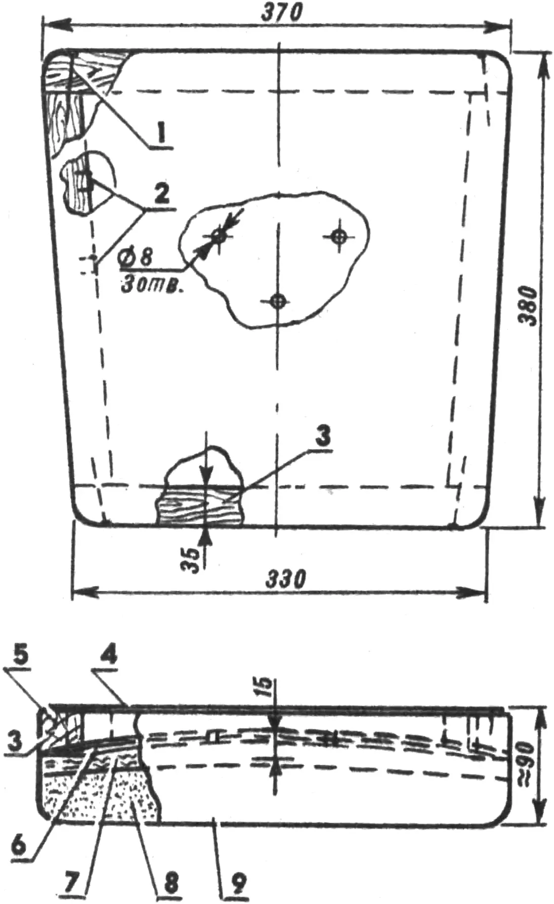
1 — nail, 2 — fastening clips, 3 — frame (30×35 mm wooden bars), 4 — covering (leatherette), 5 — fastening clips, 6 — plywood base (4 mm plywood), 7 — padding (felt), 8 — padding (50 mm foam rubber), 9 — covering (artificial leather).
Welded to the bottom of the central steering shaft (Ø 27×2.5 mm steel tube) are a steering lever assembled from 5×25 and 5×30 mm steel strips and a bushing of Ø 34×3.5 mm steel tube about 40 mm long. In three places a conical nut from a bicycle-fork bearing, bored out to an inside diameter of 27 mm, is welded to the bushing. The steering shaft is inserted from below into the steering column on the transverse beam. The column is a length of Ø 34×3.5 mm tube with a 20 mm stretch turned down to Ø 32.7 mm, inserted into the motorcycle frame’s steering column. The joint is by welding, using a 5×25 mm steel strip about 70 mm long. From above, a Ø 34×3.5 mm bushing, bored at the top for a bearing cup from a bicycle-fork steering column, is pressed into the motorcycle frame’s steering column. The same cup is also fitted on the transverse-beam steering column from below.
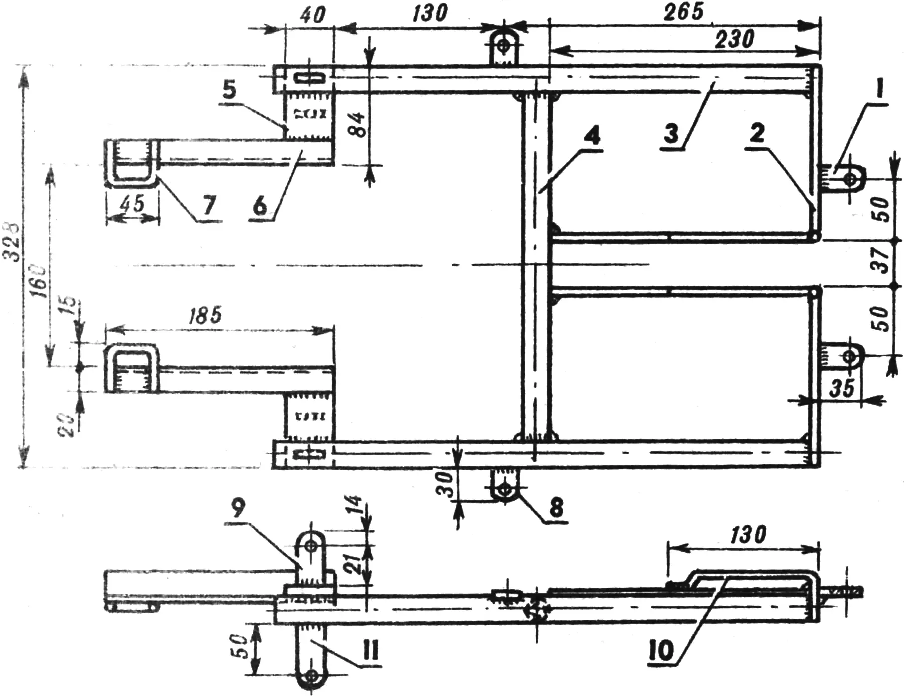
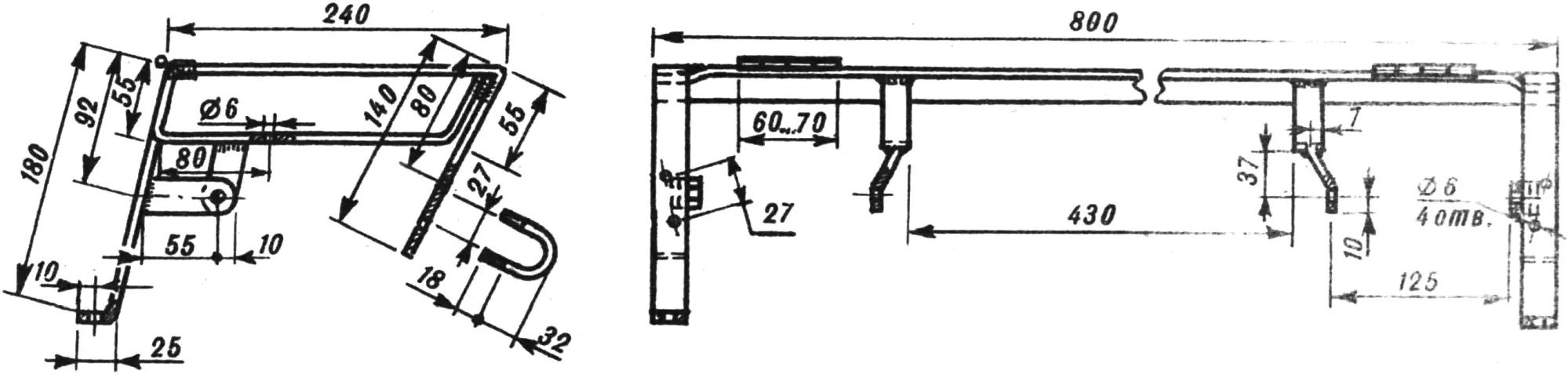
1 — bracket (4×20 mm steel strip), 2 — cross member (5×25 mm steel strip), 3 — longitudinal member (Ø22×2.5 mm steel tube), 4 — crossmember (Ø22×2.5 mm steel tube), 5 — adapter (6×40 mm steel strip), 6 — longitudinal member (20×20×4 mm steel angle), 7 — clamp (Ø 6 mm steel wire), 8 — bracket (5×25 mm steel strip), 9, 11 — brackets (5×25 mm steel strip), 10 — lock (Ø 6 mm steel wire).
The central steering shaft is connected to the handlebar by a flange — a 7×45 mm steel plate 90 mm long with Ø 10 mm holes for the handlebar brackets — welded to a bushing of Ø 34×3.5 mm tube. On the opposite side of the bushing an M34×1 mm thread is cut, and a locknut and nut are screwed onto it. To the latter, by three weld spots, is attached a conical nut of a bicycle-fork bearing bored out to an inside diameter of 27 mm. The bushing, together with the flange welded to it, is fastened to the central steering shaft by two M8 bolts with nuts and washers through through-holes in the bushing and the steering shaft.
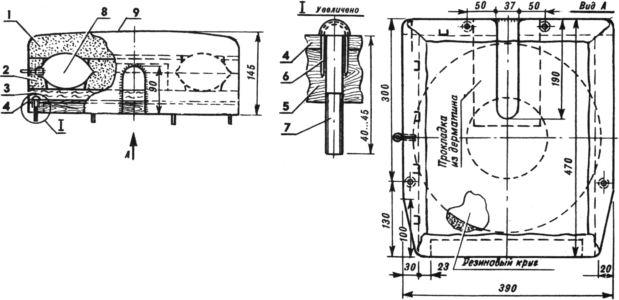
1 — cushion (50 mm foam rubber), 2 — pad (50 mm foam rubber), 3 — cushion base (20…30 mm felt), 4 — plywood base (4 mm plywood), 5 — seat base (20×30 mm wooden bars), 6 — locking clamp (Ø 1.5 mm wire), 7 — seat fastening screw, 8 — No. 2 medical rubber ring, 9 — covering (artificial leather).
The engine of my motor chair is from an M-105 motorcycle. Because the fuel tank sits comparatively low, the stock float-chamber cover on the carburetor was replaced with a cover from an Elektron scooter engine float chamber — its fitting is horizontal.
The gear-shift lever pedal was cut short by 25 mm so that it would not interfere with transferring onto the motor chair from a wheelchair.
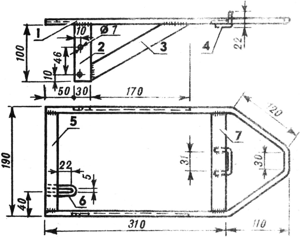
1 — base (Ø 10 mm rod), 2 — upright (5×30 mm steel strip), 3 — brace (5×25 mm steel strip), 4 — clamp (Ø 6 mm steel wire), 5 — crossmember (4×20 mm steel strip), 6 — clamp (Ø 6 mm steel wire), 7 — front crossmember (5×25 mm steel strip)
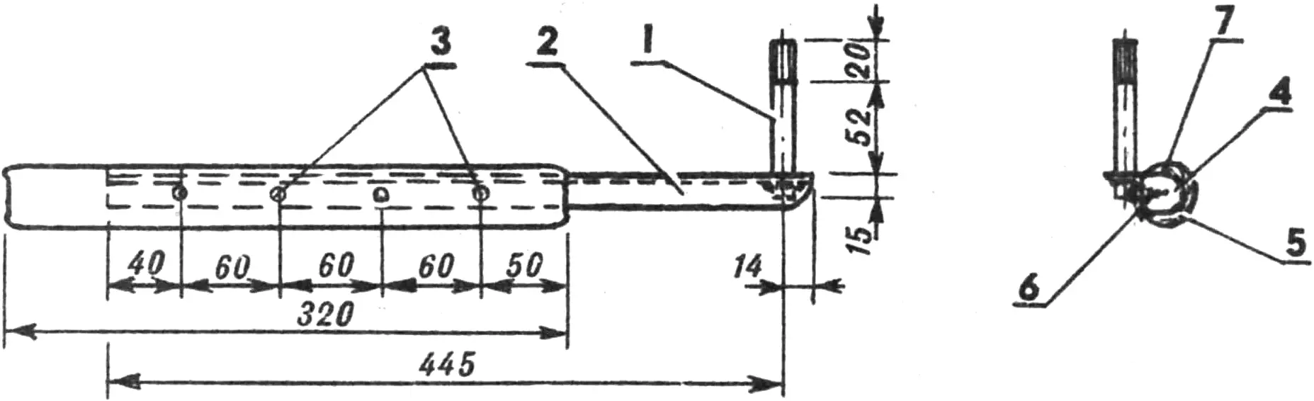
All control of the motor chair is, of course, by hand. The starting device is hand-operated too. It consists of a handle, a small lever, and a connecting strap. The starting handle is a length of Ø 22 mm steel tube bent to match the shape of the seat. An M10 bolt serving as the handle axis is welded to one end; a plastic cover from a bicycle handlebar grip is pulled onto the other.
The lever is hinged in a bushing welded to the seat-back bracket.
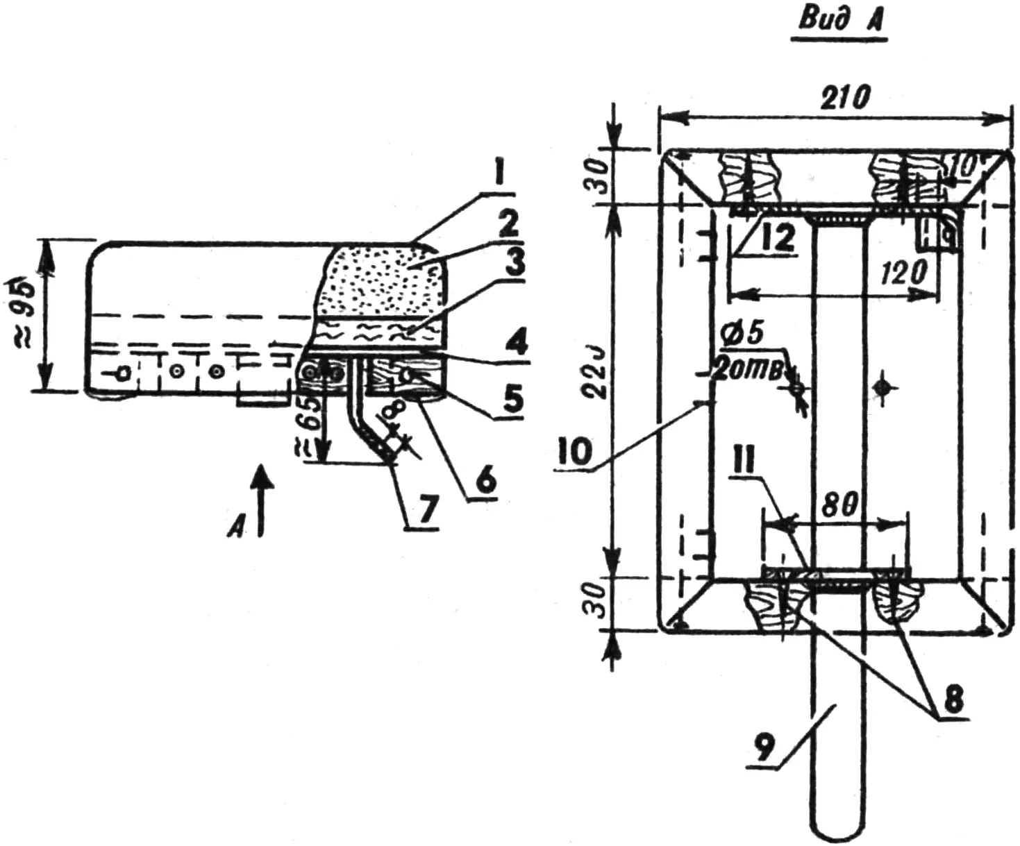
1 — covering (artificial leather), 2 — cushion (50 mm foam rubber), 3 — pad (felt), 4 — base (4 mm plywood), 5 — nail, 6 — base (20×30 mm bar), 7 — lock (4×20 mm steel strip), 8 — screws, 9 — latch (5×30 mm steel strip), 10 — clamp (Ø 1.5 mm steel wire), 11, 12 — flanges (4×20 mm steel strip).
The adapter fixed on the motorcycle kick-starter lever looks like half a doughnut; it is bent from a Ø 12 mm reinforcing bar, after which 5×30 mm and 5×25 mm steel strips are welded to it. On the kick-starter lever the adapter is fastened with a clamp bent from a Ø 6 mm reinforcing bar and an M8 bolt. The starting handle and the adapter are joined by a strong strap; instead of a strap, a steel cable can also be used quite well.
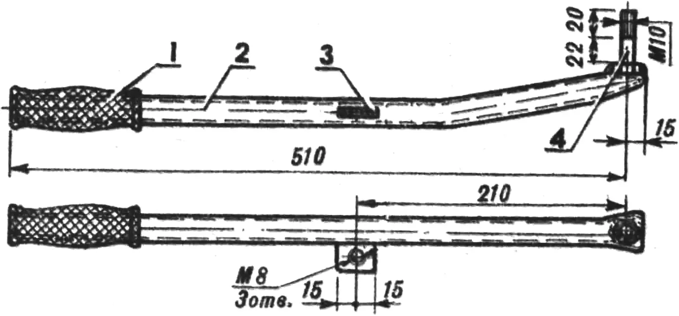
1 — grip (from a bicycle handlebar), 2 — lever (Ø 22×2.5 mm steel tube), 3 — bracket (5×25 mm steel strip), 4 — lever shaft (M10 bolt).
It should be noted that a more interesting starting device is one with a sprocket fitted on the kick-starter shaft and driven by a bushing-roller chain that in turn connects to the starting handle. A sprocket from a children’s bicycle is quite suitable for this purpose (its outside diameter should be 120…150 mm).
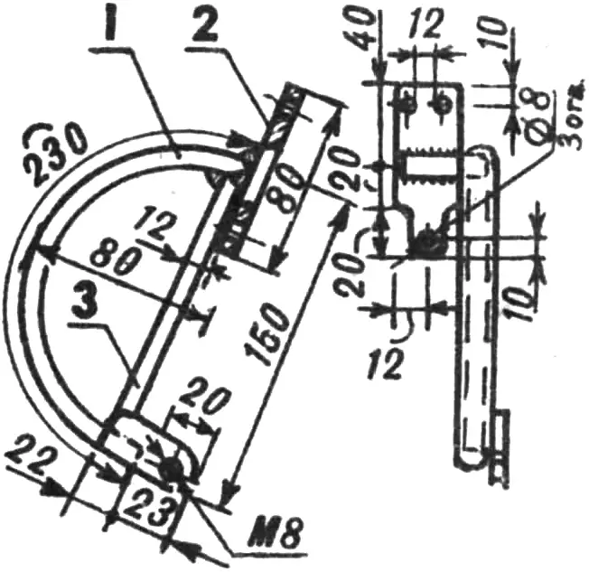
1 — arc (Ø 12 mm steel rod), 2 — flange (5×30 mm steel strip), 3 — tie (Ø 8 mm steel rod)
Gear shifting on the motor-chair engine is also done by hand. The shift lever is under the driver’s right hand, under the handlebar. It is bent from a Ø 12 mm steel rod. A plastic ball grip is fixed on one end; an axle (a length of Ø 10 mm rod) is welded to the other. The axle is fixed in a hole in the upper part of the motorcycle frame near the steering column. A bushing with a small lever welded to it (5×25 mm steel strip) is slipped onto the free end of the lever and secured on the axle with three M6 screws.
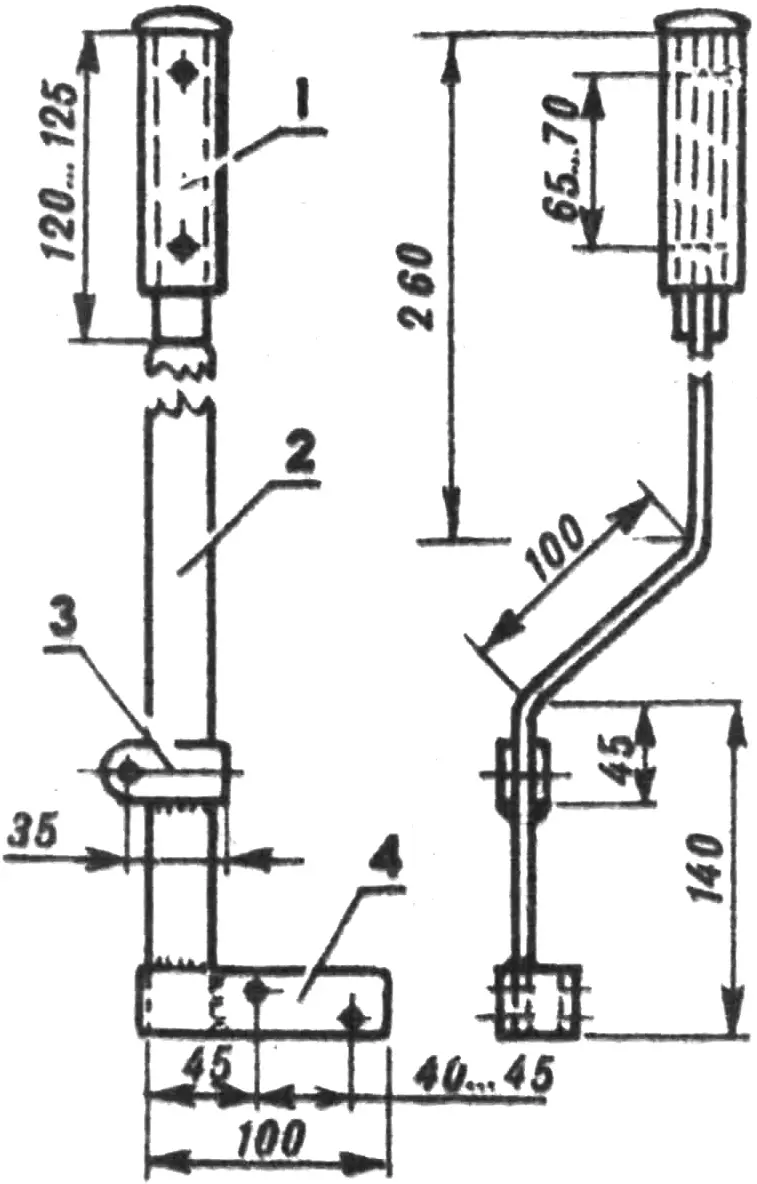
1 — grip, 2 — lever (5×30 mm steel strip), 3 — link (5×25 mm steel strip), 4 — bracket (5×30 mm steel strip).
The lower part of the gear-shift mechanism is a fork bent from Ø 12 mm rod and welded to a lever that can turn on an axle. The pedal of the stock gear-shift mechanism enters the fork jaw; when the lever (and accordingly the fork) is turned, one gear or another is engaged. The lower and upper gear-shift levers are connected by a rod made from Ø 8 mm steel rod.
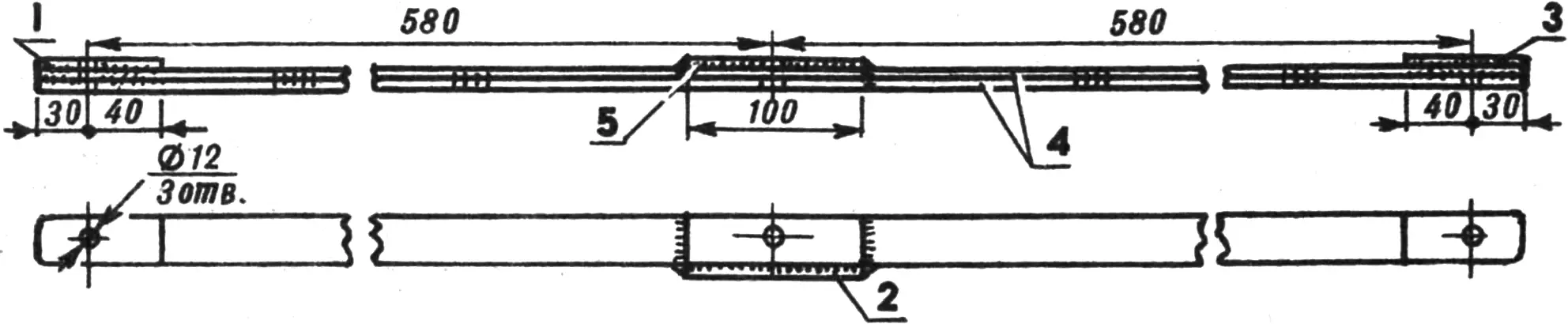
1, 3 — plates (5×25 mm steel strip), 2 — reinforcement (Ø 10 mm steel rod), 4 — crossmembers (5×25 mm steel strip), 5 — plate (5×25 mm steel strip).
The rear-brake drive is also hand-operated, by a lever made from 5×25 and 5×30 mm steel strips. A rubber grip from a motorcycle handlebar is fitted on the upper end of the lever, and the lower end is bolted to the stock brake pedal. The rod connecting the brake lever and the lever on the motor chair’s rear-wheel hub is bent from Ø 6 mm reinforcing rod. My motor vehicle also has a front brake — though only on the right wheel. In use it turned out that the front brake is used most often, because braking with the rear requires taking the right hand off the handlebar, which makes the motor chair harder to control. A more convenient arrangement seems to be driving the rear-wheel brake with a cable and a handlebar lever, as on the front. In principle this is even simpler than using a lever system.
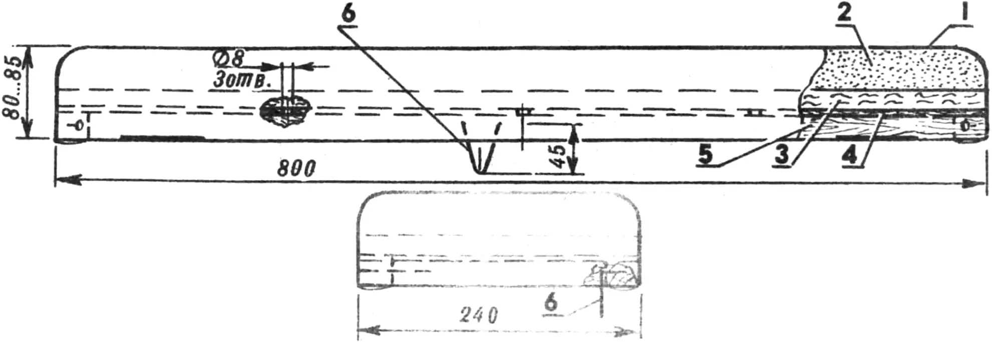
1 — covering (artificial leather), 2 — cushion (50 mm foam rubber), 3 — pad (felt), 4 — plywood base (5 mm plywood), 5 — base (20×30 mm wooden bars), 6 — spring attachment clamp (Ø 2.5 mm wire).
The motor-chair handlebar is equipped like a motorcycle’s: on the right — the carburetor throttle grip and the front-brake lever; on the left — the clutch lever. A decompressor-drive lever is also mounted on the left side of the handlebar.
Getting onto the motor chair is done from a wheelchair (mine, incidentally, has also been modified — I fitted shock absorbers and replaced the small rear wheels with one central wheel of larger diameter, taken from an old children’s bicycle). Doing this is certainly not so simple, but neither is it so difficult as to become an obstacle to riding the motor chair. After seating, the wheelchair is rolled clear of the motor-chair wheels, and I reverse out of the garage — thanks to the slope of the garage floor toward the gate. Incidentally, I am now working on a hand-drive mechanism for the wheelchair that will let it be moved in reverse.
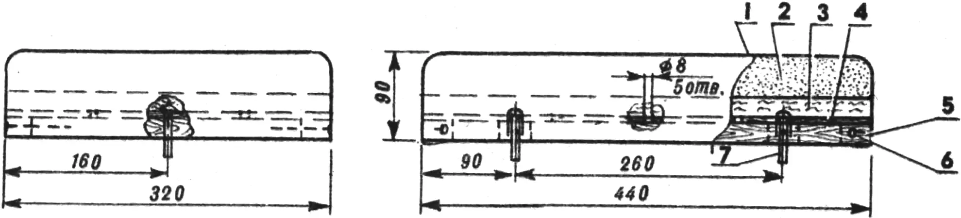
1 — covering (artificial leather), 2 — cushion (50 mm foam rubber), 3 — pad (felt), 4 — plywood base (5 mm plywood), 5 — base (20×30 mm wooden bars), 6 — nails, 7 — footrest fastening screw.
On my motor chair, on a good road, one can travel at up to 90 km/h, but going faster than 60 km/h is risky. On turns or roads with a side slope the chair is not very stable (especially with a passenger!), because the motor vehicle’s center of gravity sits high and is also shifted rearward. That is why I am now working out a new motor-chair variant — with two Elektron scooter wheels at the rear instead of one from an M-105 motorcycle. The optimum distance between the rear-axle wheels is 450 mm. The wheel suspension is intended to be independent. The wheel axles will move back 80 mm (this will also improve stability), and the rear seat will be 140…150 mm lower. The layout of this motor-chair variant is shown in my drawing.
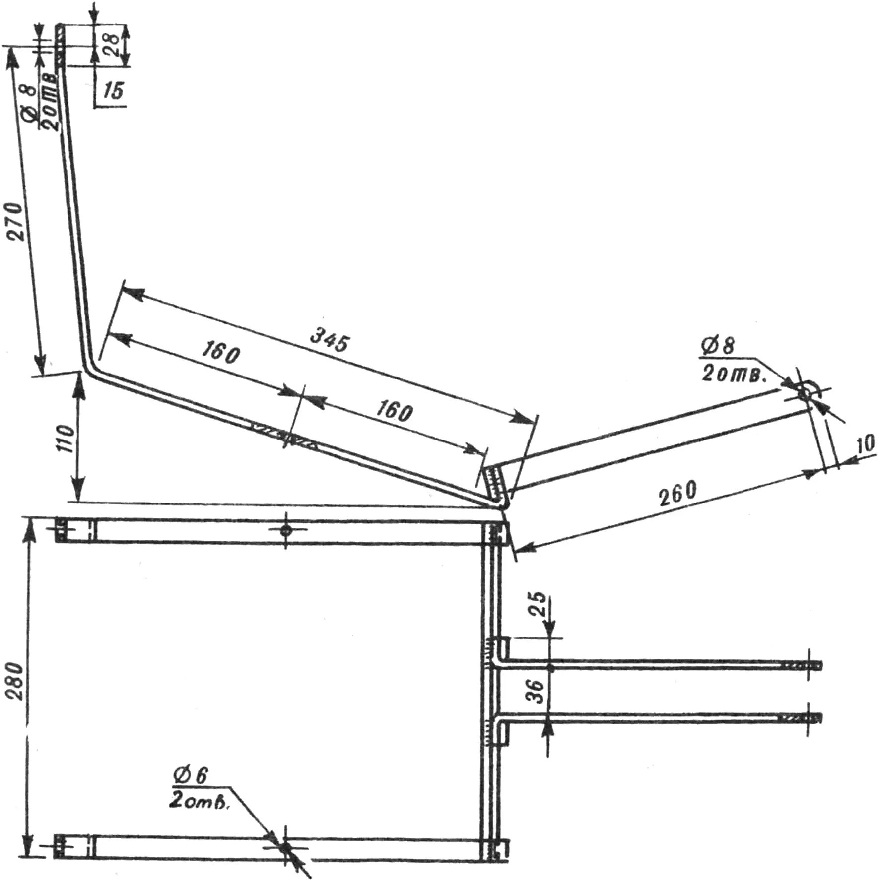
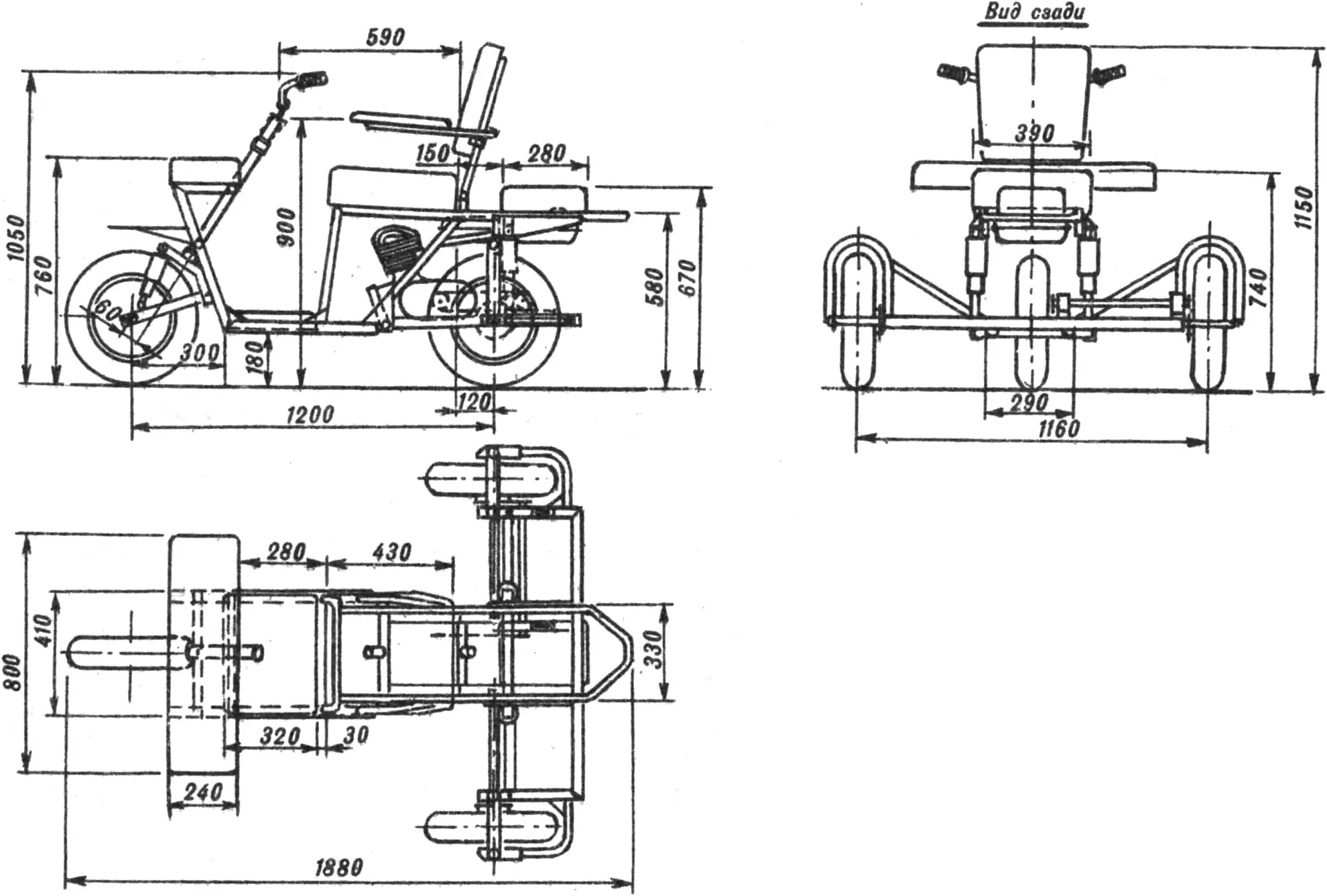
Besides the basic and improved variants, I also sketched two more layouts that are more convenient, more stable, and at the same time simple to make. I believe they will also attract the attention of readers interested in this kind of transport. I consider the last variant the most interesting.
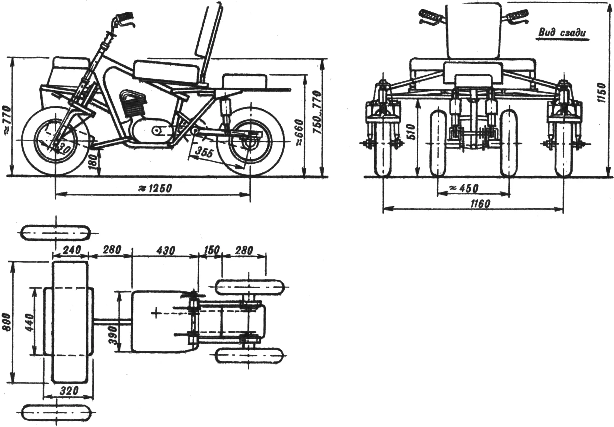
In both the third and the fourth motor-chair variants only the right rear wheels are driven, which frees the design from a heavy and expensive differential. The drive from the engine to the driving wheel is by a two-stage chain drive using an intermediate shaft.
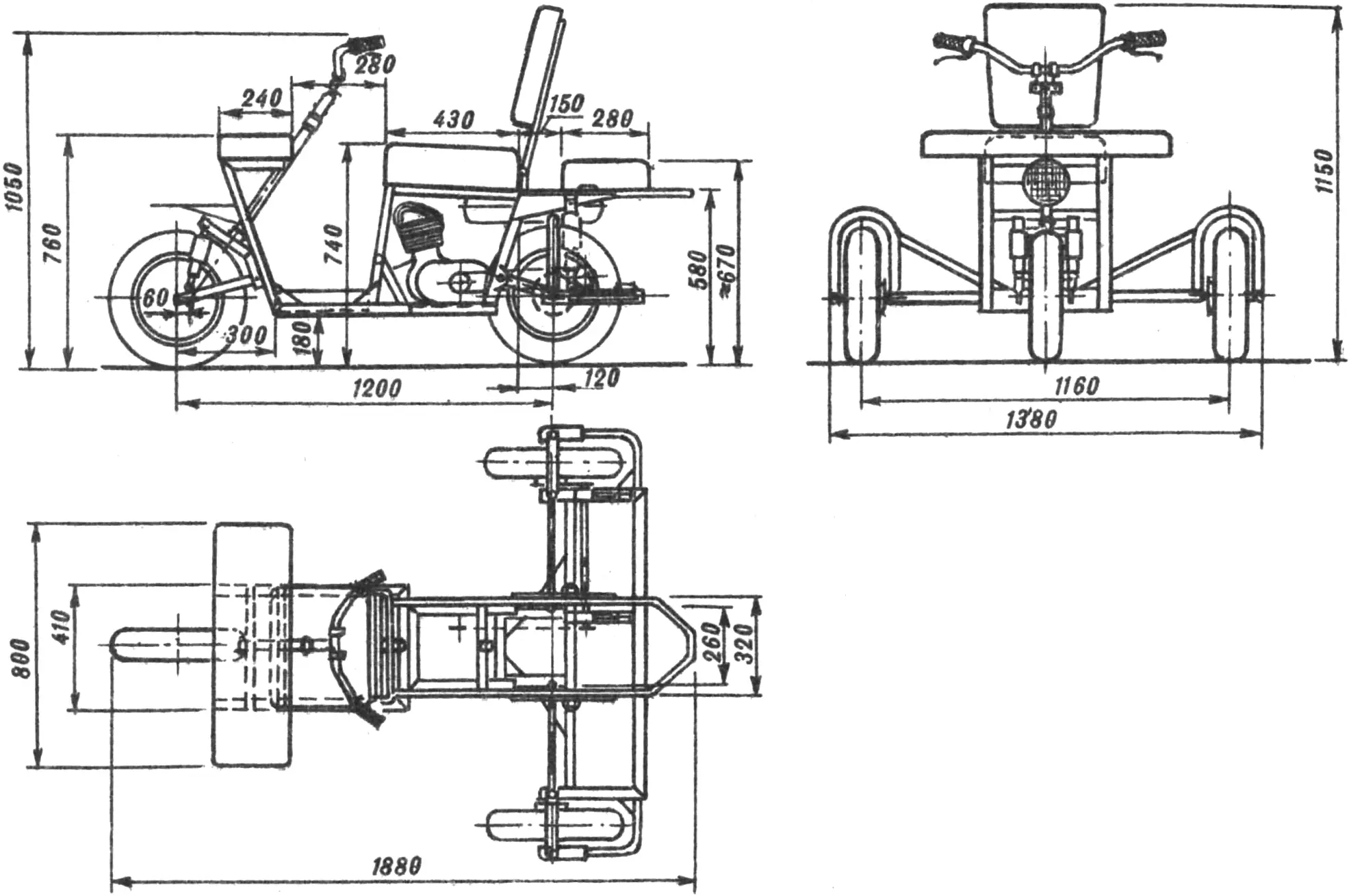
It should be noted that the dimensions of the driver’s seat, the soft-hood backrest, and the armrests are the same in all variants, and if anyone wants to repeat my designs, I can assure them that the dimensions have been well proven in practice and are quite acceptable for many spinal patients.
Any of the four variants can be fitted with a hand drive (front and rear), whose design is shown in my drawing. Such a drive makes it possible, when needed (for example, if the engine fails), to move at 2…5 km/h, and also helps turn around in a tight spot or reverse.
That, properly speaking, is all about my work. From my own experience I know well how much spinal patients need a light, maneuverable vehicle that is convenient for boarding and rest, reliable in service, compact, and sufficiently powerful. Unfortunately, industry does not produce such vehicles. Of course, there are Serpukhov-plant motor carriages and Zaporozhets cars with hand controls. But unfortunately they do not meet many requirements of people who have lost mobility. If such a light, maneuverable, and inexpensive vehicle were produced in series, I think it would find enormous demand and could substantially improve the hard daily life of “spinal patients” and of many other non-ambulatory or poorly mobile disabled people.
“M-K” 5’92, Y. FEOFILAKTOV
Recommend to read
 Rare box of use
Chetyrehmillimetrovoy Small sheet of plywood, 10 mm thick plate, nails or screws: all this is enough to make an extra drawer in the kitchen table with a folding cover. It is possible to... IN FLIGHT THE AIRPLANE HAD
Introducing radio controlled model aircraft for training flights. The prototype was popular among modelers from different countries models "Corkscrew" (Corkscrew) is an American athlete...
