 If some time ago the author said that he would have to “reinvent the wheel”, he would take it as a joke. However, the skepticism has vanished after discovering a magazine with a model of “vetrohod”, made by Alexander Twins. The model had air and propellers sitting on the inclined shaft, and moved strictly against the wind under the action… of the wind!
It seemed tempting to do on this single principle vetrohod: two Bicycle wheels, if the spokes in pairs to paste over thick fabric, could serve as a multi-blade wind turbine, the rotating propeller via a chain drive.
But what to do when there is no wind? You can turn the wheels pedals! Then the wheels turn into propellers, and the propeller as in the previous case, is used lo its intended purpose. However, this transmission was quite difficult and promised big losses.
And if the movement in the water use land bike?!
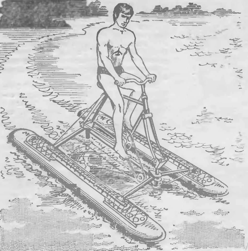
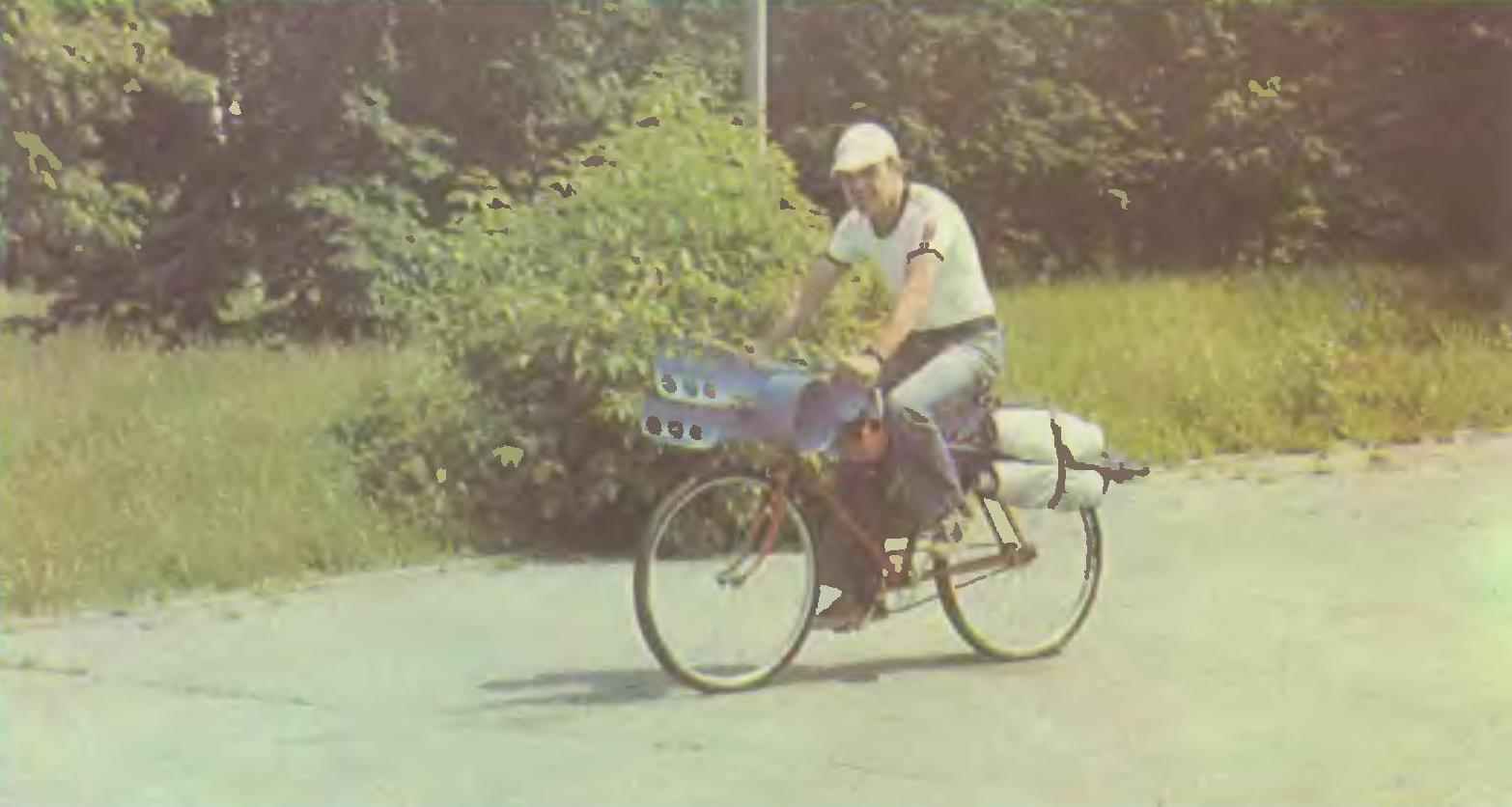
In the end all resulted in design which are presented to the readers. It is a prefix to a road or tourist bike. When the land design of folded, sheathed and strapped to the bike frame side.
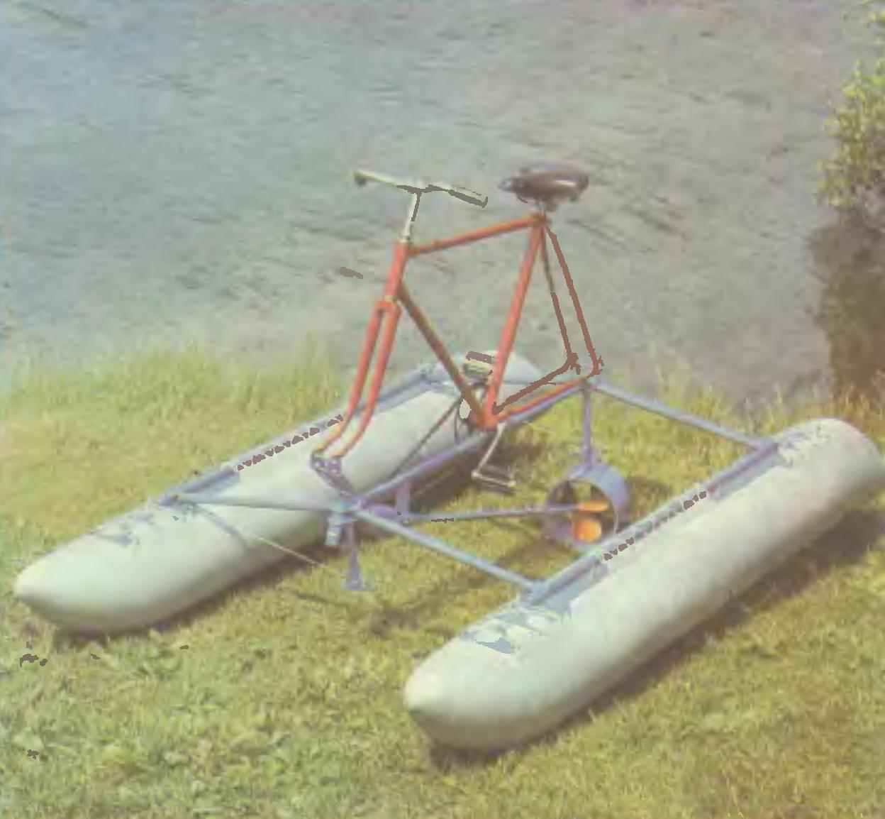
On the waterfront the console and laid it out, put it on a Bicycle frame without wheels, inflate the floats, and you can sail through the English channel, Biscay with or through the “furious fifties”, not forgetting to take with them… the wheels. But seriously, such veloimperia good for country walks, water recreation, Hiking trails and fishing.
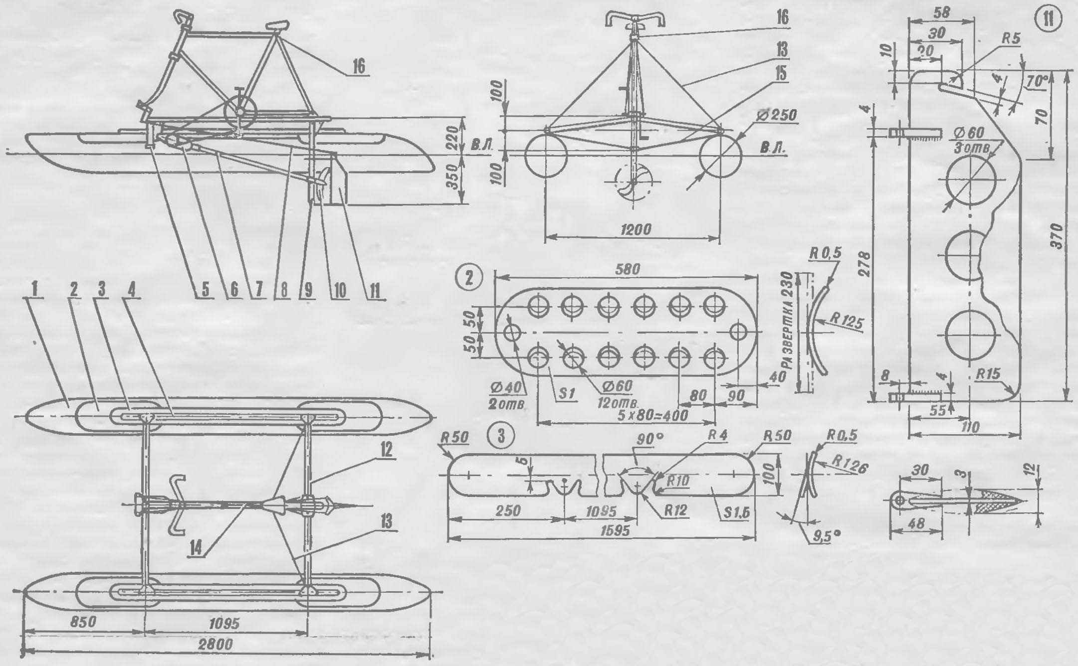
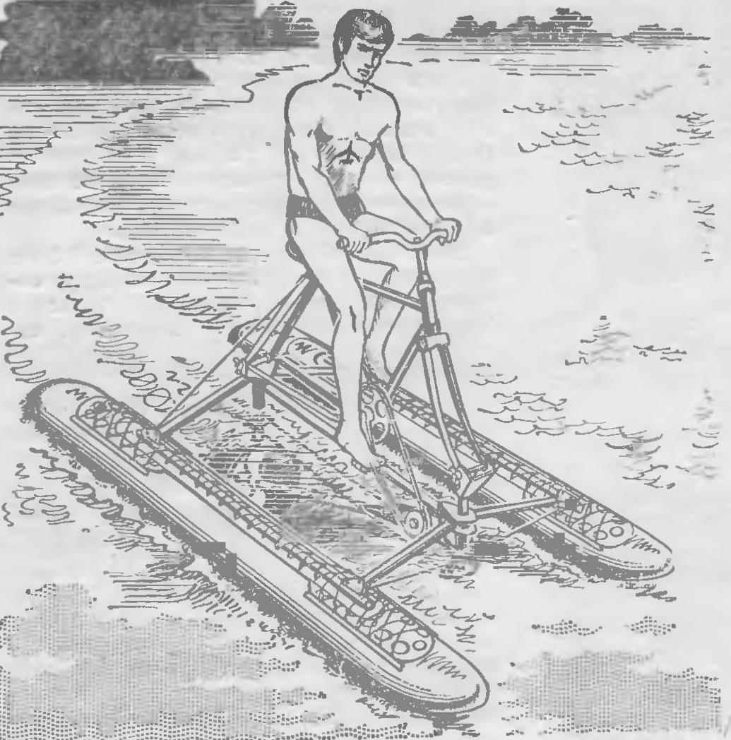
Fig. 1. Selectamark:
1 — float,
2 — plate,
3 — the bed,
4 — longitudinal beam of the frame,
5 — front vertical strut,
6 — gear (hand drill),
7 — propeller shaft
8 — drive vehicles,
9 — rear vertical strut,
10 — thruster,
11 — the wheel
12 — cross beam of the frame,
13, 15 — brace,
14 — the frame of the bike,
16 — castle.
The tinkerers who wish to produce such a console, you will need several metres of dural pipes and steel cable lock for frame and 6-7 m2 waterproof fabric for floats. If you live close to a body of water can be done purely water transport — “vodopad”, based on a Bicycle frame without wheels.
Malopeschanka consists of a power frame, inflatable floats and screw propulsion. The load-bearing element of the frame of the Central beam, which via a crossbar pivotally connected to the longitudinal beams. Bottom mounted front and rear folding racks that serve as spacers for braces connecting the ends of rails. The outer ends of the rear bars are connected by braces to the frame of the bike, keeping it from stalling on the side, and bars — from folding back.
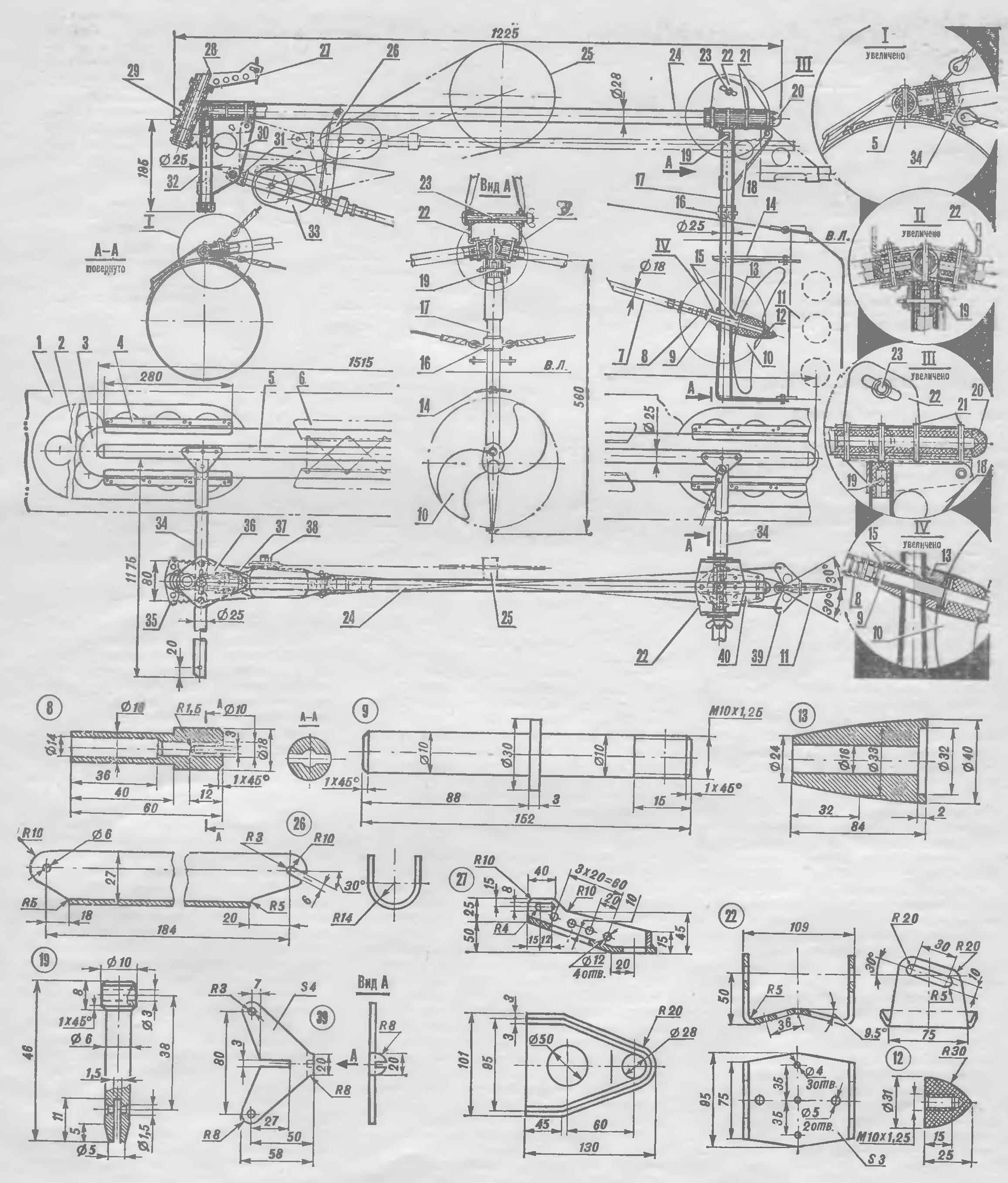
Fig. 2. Power transmission and elements of the framework:
1 — float,
2 — plate,
3 — the bed,
4 — alignment tab,
5 — longitudinal beam (tube ø 25X1 5),
6 — valve,
7 — propeller shaft (tube ø 18X1),
8 — tip of the propeller shaft,
9 — axle shaft,
10 — screw,
11 — the wheel
12 — nut PCB),
13 — the bearing housing,
14 — protivoyazvennoe plate,
15 — bushing (Teflon, kaprolon),
16 — nozzle,
17 — back front,
18 — rear bracket,
19 — removable pin
20 — tube,
21 — rivet,
22 — bracket,
23 — screw with nut lamb,
24 — the Central beam (tube ø 26X2),
25 — Bicycle sprocket
26 — turning brace,
27 — front bracket (top view conventionally not shown;
28 — the axle bracket (pipe ø 28X3),
29 — bushing (pipe ø 34X2,5),
30 — swivel bracket,
31 — plug,
32 — front (tube ø 25X1,5),
33 — drive (hand drill),
34 — cross beam,
35 — rocker,
36 — front top knize,
37 — front lower knize,
38 — sprocket reducer,
39 — rocker helm,
40 — rear kniza.
To transfer the load from the power frame in inflatable floats from the bottom to the longitudinal beams riveted lodgements with removable plates.
Inflatable floats pressurewhat to them for the tabs or attached using hook and”brambles”.
The propeller consists of gearbox, propeller shaft, propeller and rudder mounted behind it, connected to the front fork of the bike with a special harness. At the ends of the Central beam installed front and rear attachment points of attachment to the Bicycle frame.
The design of these elements and their compounds can be different depending on the technological capabilities, skills, tastes and ingenuity of the performer.
With all the desire for constructive n technological simplicity the author has failed to avoid turning and welding. Their use was dictated by the desire to facilitate the mechanism, providing it with sufficient strength and rigidity.
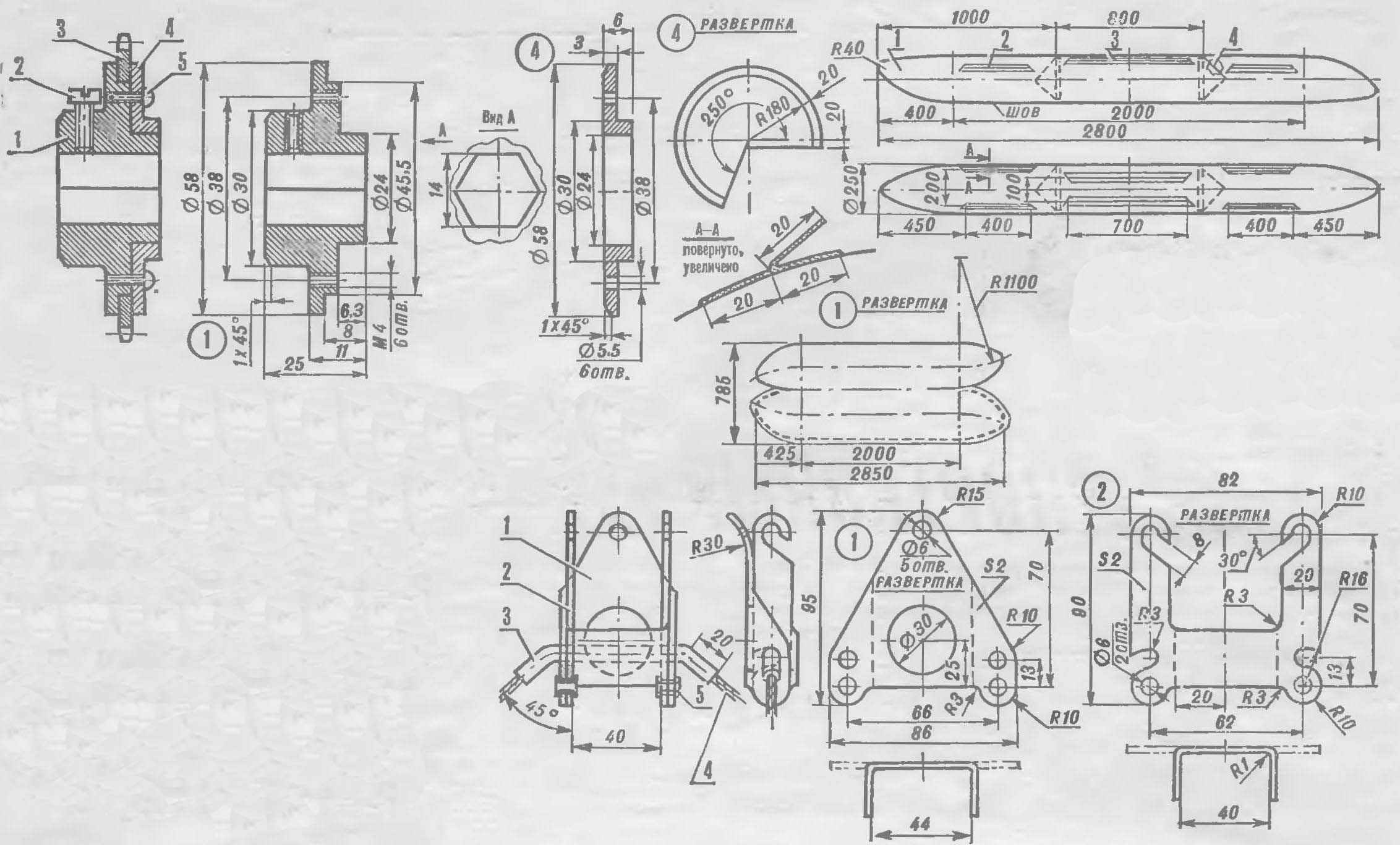
Fig. 3. Star reducer Assembly:
1 — housing,
2 — locking screw M6
3 — the crown of the Bicycle sprocket ø 80 mm,
4 — cover,
5 — WINNT M4.
Fig. 4. Float:
1 — shell
2, 3 — reeds,
4 — the diaphragm.
Fig. 5. Castle:
1 — housing,
2 — double hook,
3 — tube ø 6 X1,
4, upper brace,
5 — tubular rivets.
 The power transmission. As a reducer applied manual two-speed drill with a gear ratio of 7:1. Together with the chain it provides a gear ratio between the shaft of the pedals and propeller 21 : 1. Mounted drill through installed on the axis of the plug. Instead of side handles for hex shank drill planted small sprocket of the chain transmission, instead of the cartridge shaft drive.
To improve efficiency, I replaced first applied a three-bladed propeller ø 200 mm ø 270 mm, two-bladed, laminated of fiberglass epoxy resin. Screw left rotation, a pitch of about 230 mm. the Shape and thickness of the blades are chosen so that the angle of their installation varies with the load due to elastic deformation, providing for all modes of movement the step, close to the optimum.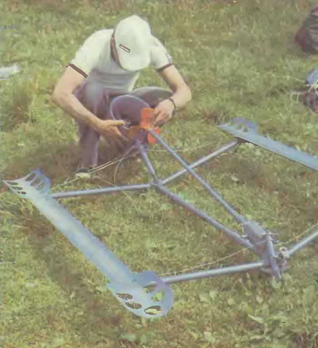
The propeller can be made from metal or use prepared, for example, from outboard engine “Breeze-13” or “Breeze-12”.
To simplify construction reduce the size of the console when folded, I have deleted and earlier provided an annular nozzle around the propeller. Instead, it installed easier protivojinfectionnaya plate that protects from suction of air.
In the thrust bearing of the propeller shaft mounted PTFE bushings, able to work in water without lubrication (you can make them from caprolon).
Inflatable floats are constructed from rubberized fabric (“silverfish”). To increase the airtightness and to protect cotton fabric from getting wet and rotting, its back covered with two layers of the sealant 51-G-10, diluted with gasoline B-70 in a ratio of 1 : 1.
 For floats suitable nylon or Dacron cloth impregnated with a sealant 51-G-10 or U-30МЭС-5, polyurethane or glue “Moment-1”, diluted in turpentine in the ratio of 1:1 by volume.
For fastening to the locating blocks on the floats and glued the tabs from a strip of the same fabric with a width of 80-100 mm, folded as shown in the figure. The reeds better to glue to inflated floats on the finished tool trays and plates.
If you plan to mount the floats with lace-up tabs make holes ø 10 mm increments of 80-100 mm, and in the loop reeds threaded spokes of dural electrodes ø 3 mm.
To improve the survivability of veloimperia each of the floats is divided into three compartments by transverse bulkheads in the form of conical diaphragms of the same fabric. This form of diaphragm is under pressure and allows you to turn off the floats without folds. Bulkheads glued in the last turn, leaving this in the middle of the float open section of the seam length in feet. Seam better to place the bottom.
Pump floats air with a rubber pump (frogs). Don’t forget in each compartment of the float to attach the valves with a removable nipple from the rubber boats.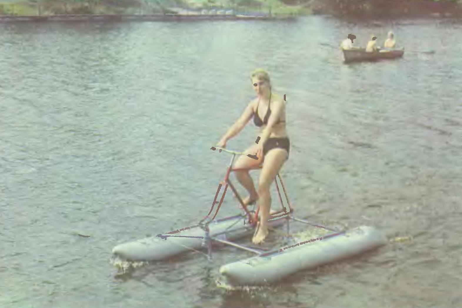
The tip floats better applied to the wall on the boob, which you can make from foam, wood, papier-mache, clay. After gluing all the seams have fluff sealant, then seal seams with strips of fabric width of 20 mm.
To increase integrity, improve the appearance and water-repellency imparting floats are painted with an elastic paint, manufactured by prescription: one tube of glue “Moment-1”, 0.5 litre of turpentine and 100 g of aluminum powder.
In conclusion, a few words on the further improvement of the design. In principle, it is permissible to replace the drill and inclined shaft to a vertical column, excluding the steering wheel. This will allow to reduce the weight, dimensions and eliminates the need to separate the chain. Interesting to try instead of screws to apply lastby mover. And finally, create a console that does not require removal of the wheels.
TECHNICAL CHARACTERISTICS
Own weight of veloimperia, kg – 26
Capacity afloat, kg 100-120
The volume of the floats, l – 256
Speed on water, km/h 8-10
Overall dimensions, mm:
— veloimperia afloat – 2800X1450X1250
set — top box when folded – 2000Х250Х150
Inideology:
Recommend to read
 “PUMA” WHEELED
In the early 1980-ies of the IVECO group by order of the Italian army began construction of armored vehicle of a new family of wheeled APCS (4x4 and 6x6), received the official name of... CAR PLOWING
Motorists that have a cottage or the HOMESTEAD, in the spring together take up the shovel on par with car-free part of humanity. Meanwhile, they could avoid such wastage of own physical...
