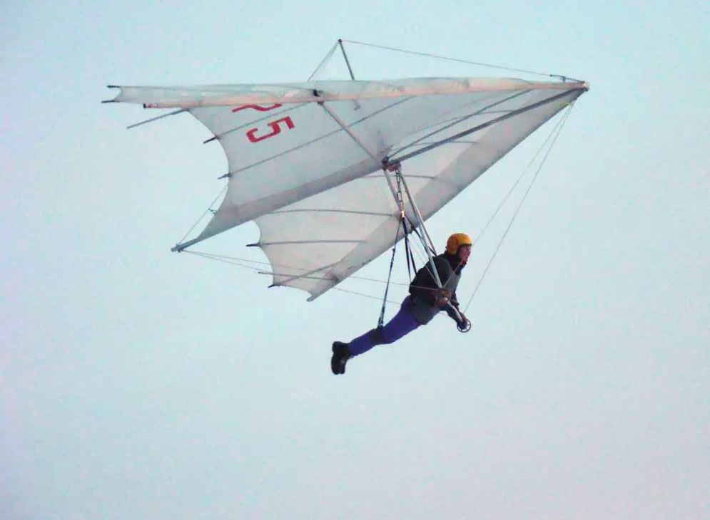
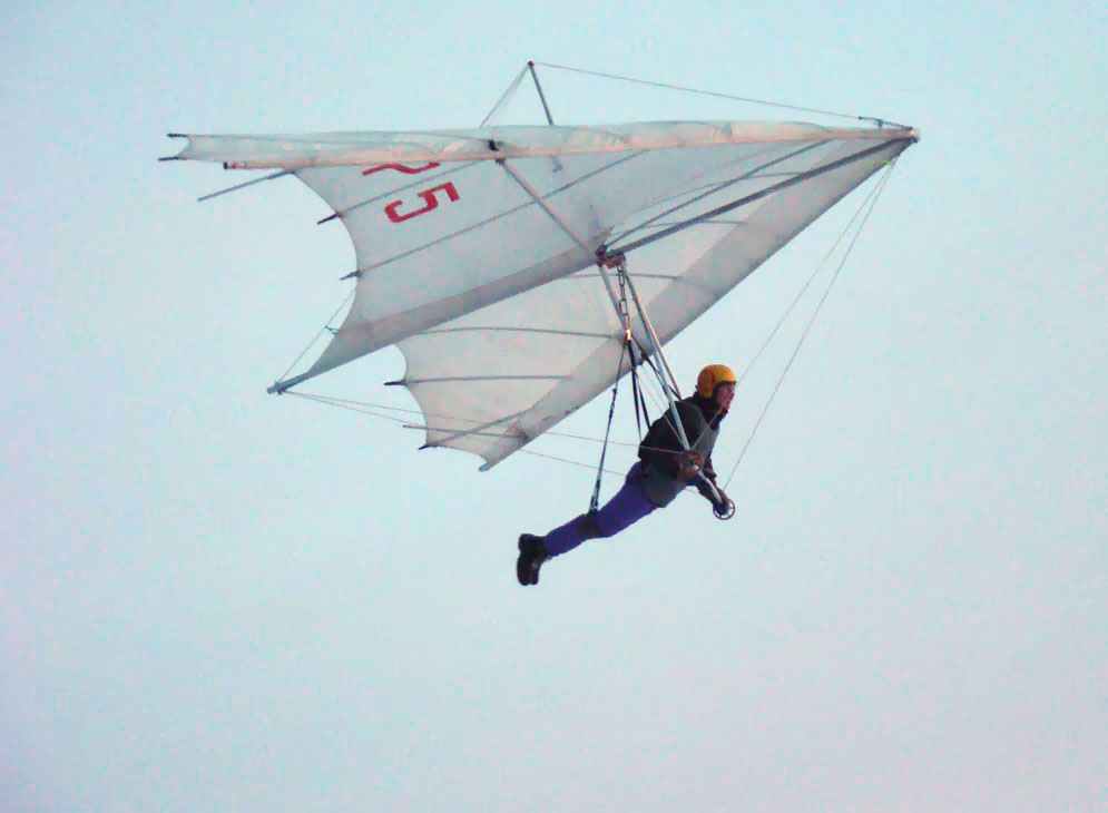
 The design of the “Slavutich-UT” is a classic: tubular frame, cable system stretching and edging with the main elements of armor. The device is equipped with removable wheels and safety antieconomy device. The kit also includes a suspension system.
The frame is tubular, the main elements are connected together pivotally in the nasal, Central and lateral nodes.
 The diameter of the pipes leading edges and keel — 42X1 mm, cross — 42X1,5 mm. they are All made of duralumin D-16T, each has technological and operational connectors. In pipes forming a front edge, two of them; in these places there are bougie. The middle part of the front edge side in the area of site meter reinforced bougie.
The keel has technological and operational connectors. The first is to strengthen the Central node.
Cross pipe consists of two parts, symmetrical relative to the Central node, each has an operational connector.
The location and number of ports were selected based on the conditions of ensuring the strength, resource, and minimum weight when size of the glider in the package is not more than 2,200 mm In the open ends of the pipes inserted plastic core, and the connections with the nodes are the same plastic curved puck.
The side and keel of the pipe is pivotally connected to the forward node, which represents the spinner and consists of a U-shaped steel plate with a channel and an earring.
The Central node consists of two channels. In the upper part is attached to the mast support cables; installs in the lower steering linkage.
Side node frame fork construction: nodes of fastening of cross bar and side cables apart, which allowed to exclude the impact of the pipe joint in a side knot on the aerodynamics of the wing.
Steering linkage consists of two side plates and a handle connected by a hinge. The sides have the technological plugs in case replacing the straight sections when they break.
 Tether systemthat holds the frame of the hang glider, consists of top and bottom steel cables d 2.5 mm, clamped through shackles in earrings, clips and carabiner. The upper brace connects the nasal and the lateral nodes, and a node on the keel through the top of the mast. Cables near the top have the limiters moved. Between the nose knot and rope, and between the left side and a cable, installed the toothed adjusting elements of the longitudinal and transverse tensioning cables.
The lower cables are attached to the bracket on the trapeze and do not have the adjusting elements. The carbine front of them are increased requirements for durability and quality workmanship.
All cables have the machine sealing of the ends of the sleeve by compression and coated with a vinyl chloride sheath.
For mounting in main nodes of the glider uses M8 bolts, the auxiliary — less M6. Permanent connections are made using self-locking nuts, split — locking pins.
 Antiekeradio device of the glider comprises three main elements. Chief among them is the keel profiled Lata established between the Central and nasal node. It provides the constancy of the shape of the nose of the wing in Kileva section.
Root hard armor plating, the ends of which are connected by ropes to the mast, give the profile a reverse curvature in the cross section of the wing at low angles of attack. And the last element contributing to the stability of the device — end support for the sheathing, limiting the decrease in the twist end of the wing at low angles of attack.
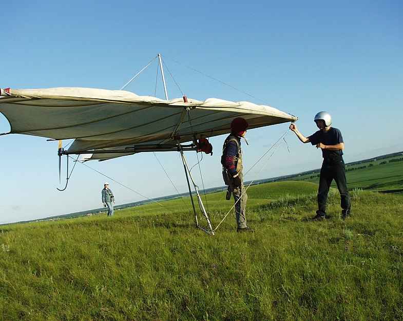
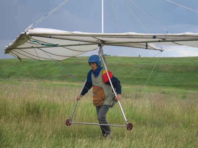
To ensure safety in the event of rough landings while training glider equipped with quick-release wheels that are installed on the handle of a trapezoid.
Suspension system formed quilted cradle, belts, rope, snap hook and stirrup. It helps to easily make the takeoff and landing, but the main thing — to perform a long flight: in flight the athlete lies like a cradle.
 The covering of the glider consists of a fabric “sails”, the side and keel pockets. Shaping the surface of the wing in flight, the aerodynamic load on the bearing surface, deformation of the framework — the whole complex of factors inherent in the sail cut on the leading edge, ciliau section and in the section “oblique” armor. Material is a Dacron fabric sailing “Boat-Up”.
To ensure the formation of the wing in the casing at a joint of panels completed laderman in which to insert armor. Eight of them focused on a stream of four — “skew”. Themselves armor — tubular, d 16X1,5 mm, of high density polyethylene. The bow of those that are oriented to the flow has a constant magnitude radius of 400 mm and a straight tail section.
Due to the fact that the volume of articles makes it impossible to publish the drawings with detailing, production and technological instructions, apparatus made according to the information presented here, should be subjected to examination in technical committees of the Federations and clubs DOSAAF according to the current technical requirements of a self-made hang gliders.
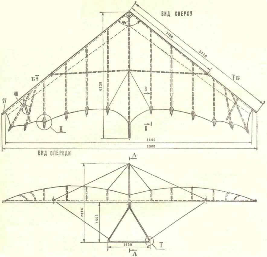
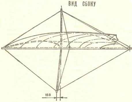

Fig. 1. The design of the “Slavutich-UT”:
1 — Gotic nasal node
2 — channel,
3 — hook,
4 — gear,
5 — top front wire stretch marks
6 — profile tube,
7 — rubber washer
8 — top,
9 is a lateral wire of the upper stretch marks
10 — rear upper cable stretch marks
11 trusses support the sheathing,
12 — mast,
13 — upper channel of the Central unit,
14 is a carbine rear portion of the skin,
15 — keel pocket,
16 — Rear keel,
17 — keel stub
18 — rear lower cables stretch marks
19, the lower channel of the Central unit,
20 — hinge suspension of the pilot,
21 — side pipe of a trapezoid,
22 — the front of the keel,
23 — front wire of the lower stretch marks
24 — carbine,
25 — eye of the nose node,
26 — the nose plug,
27 — side pipe,
28 — plating,
29 — transverse pipe,
30 — gnetic side pipes
31 — side tether the lower stretch marks
32 — bolt trapezoid to the Central node,
33—bolt side pipes of a trapezoid,
34 — the wheel
35 — axle shaft,
36 —Lata
37 — bracket,
38 — the shock cord,
39 plug,
40 — end support.
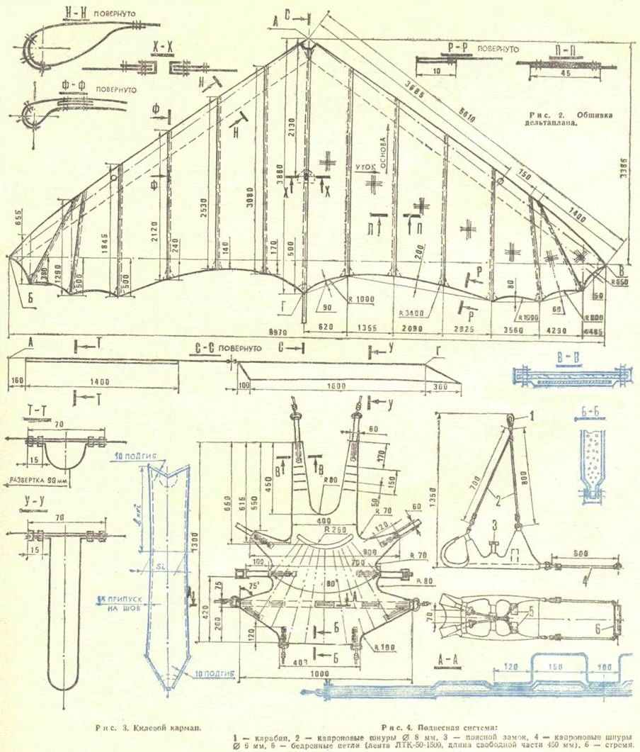
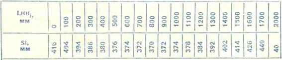
Table cutting the keel pocket
Fig. 1. The end of the side pocket:
1 — tape LTK-24-1200,
2 — line AB.
Fig. 2. Scheme bookmarks plating:
1 — edge of the fabric, taking account of the overlap on the seam,
2 — overlap the front edge of the trim and side pocket
3 — the overlap on the keel,
4 — edge of the fabric, taking account of the overlap on the seam.
Fig. 3. The nasal part of the skin:
1 — side pocket,
2 — line AB,
3 — tape LDMP-27-1600,
4 — seams (thread No. 15),
5 boat.
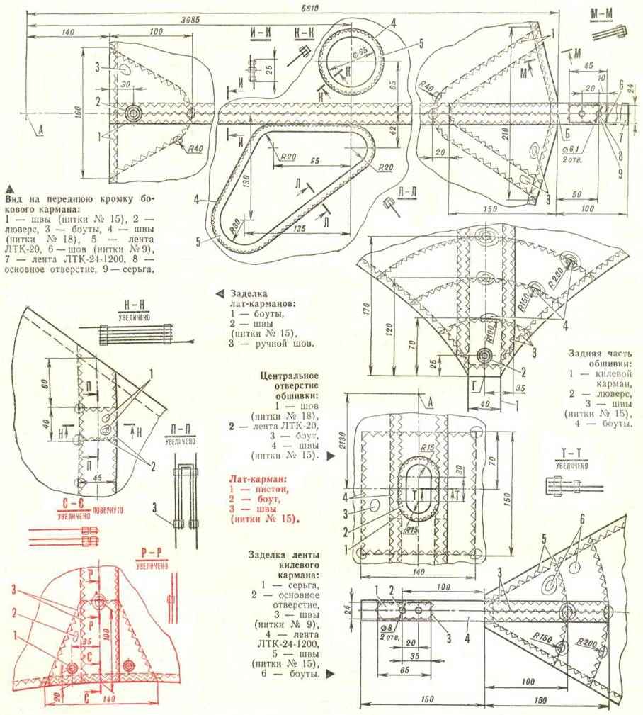

TABLE 1. The value of tabs to the front edge of the casing and side pockets.

TABLE 2. The size of the tabs on the keel.

Basic data technical characteristics of the hang glider
The material from the magazine modelist-KONSTRUKTOR 1982-10
Recommend to read
 ALL-TERRAIN AMPHIBIAN
The amphibious all-terrain vehicle was built over five years and first left the garage in 1969. Traveled more than 1000 km. Tested on rough terrain, on snow, on water, on marshy, sandy,...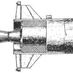 IMPORTANT — HEIGHT
Booster "Diamond-A" in November 1965 into orbit the first French artificial satellite of the Earth. France became the third space power. Length of the rocket "Diamond-A" is about 19 m,...
