
When I needed a megaphone, I looked at the prices of industrial Chinese products: as it turned out, they cost from $45 to $235, and I decided that I could assemble a similar device with my own hands in a couple of hours.
A megaphone (or loudspeaker), the electrical circuit of which I recommend and present below, will be useful during sports competitions, in advertising, in conditions of constantly elevated noise, for games with a child, and even in a minibus for broadcasting information to passengers in the rear seats.
Under today’s traffic regulations, drivers and passengers are not allowed to use loudspeaker devices (except for vehicles of emergency services), so the proposed device can be used for other purposes not prohibited by law, that is, not outside, but inside the car cabin. I admit that I specifically planned the device as a car megaphone for trips in a large group in my minivan.
The circuit design is easy to replicate not only for a radio amateur, but even for a car owner with little experience in radio engineering. The circuit requires no tuning; with serviceable components and correct assembly, the device starts working immediately. Moreover, the undistorted loudness of such a homemade unit is not inferior to that of an inexpensive industrial Chinese analogue.
The distinctive features of the proposed design are: a high gain factor, simplicity and reliability of the circuit, its orientation toward autonomous operation (from batteries or accumulators with a total voltage of 12 V), and the absence of dual-polarity power supply.
Thus, the megaphone is a circuit that amplifies (hundreds of times over) the level of the input signal. Let us consider in more detail the operating principle and the electrical circuit of the device (Fig. 1).
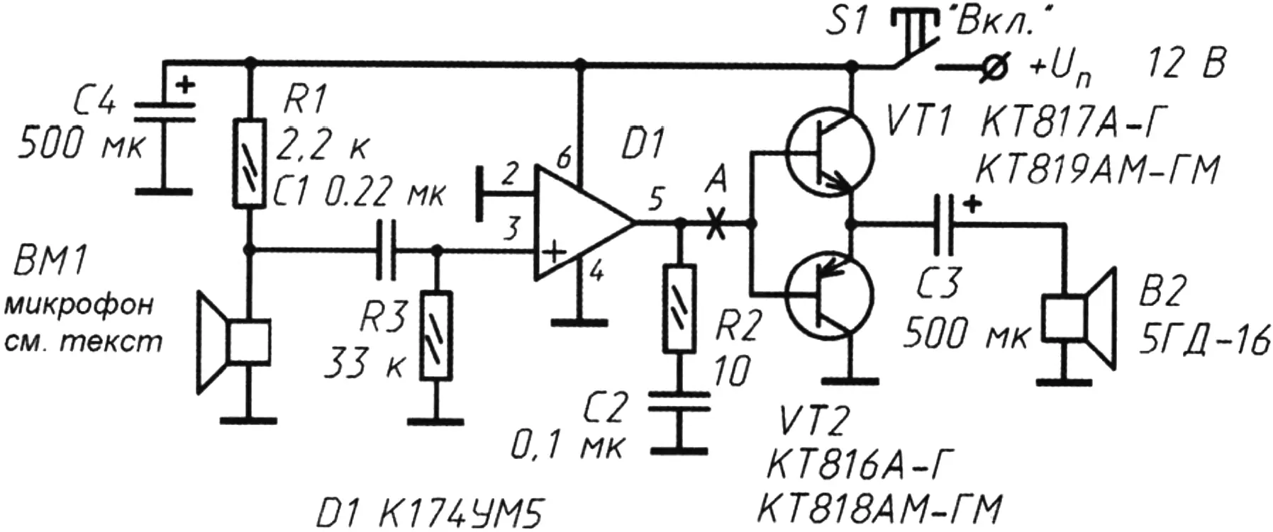
IC DA1 is a power amplifier with an output power of 2 W into a 4 Ω load for use in the audio paths of equipment and is connected in a classic circuit.
However, since the amplified signal from the IC output is fed to a “driver” transistor stage, the power amplifier has a higher output power, reaching, according to my measurements, 4.5…4.8 W at a supply voltage of 12 V. This power is quite sufficient to conduct outdoor tours or inform listeners seated in the rear seats of a minivan or microbus without straining one’s voice.
A highly sensitive microphone, taken by me from an old Nokia 3310 mobile phone, is connected to the high-impedance input of the IC (by the way, microphones from other mobile phones also fit in appearance, for example, LG KP500, KP501, KS910, KF510, etc.). Electret microphones of the MKE type may also be suitable — this series includes several models, but the MKE-3 is the most popular.
As can be seen from the circuit, the device is built around a single amplifier IC, K174UN5, thanks to which signal amplification is achieved (without loss of quality).
The IC output is connected to an output stage based on a complementary pair of silicon transistors, which in this implementation provide tenfold amplification of the audio signal (possible transistor replacement options are shown in Fig. 1). Electrolytic capacitor C3 (rated for 25 – 35 V) is necessary to eliminate the DC component at the dynamic head (it protects it at peak signal values).
It is not advisable to reduce the capacitance below 200 µF, since the maximum signal amplitude at the amplifier output depends on this. An electrolytic capacitor from Tesla works well as C3.
The R2C2 chain is a compensation chain; it prevents sound distortion.
However, upon first switching on, the radio amateur himself may decide, based on the characteristics of the speakers and transistor pair used, whether this chain is necessary. Thus, the specified RC chain can be removed from the circuit without consequences.
In practice, it turned out that smooth adjustment of the volume (power) level of the device can be provided by using a variable resistor of 22…33 kΩ of series B (with a linear characteristic) instead of resistor R3. In this case, pin 3 of the K174UN5 IC is connected to the wiper of the variable resistor.
By changing the capacitance of capacitor C1 within 0.05 – 1.5 µF, the sound volume and signal tone can be corrected within small limits. A tolerance of 10 – 15% is acceptable.
IC DA1 must be mounted on a heat sink without fail.
I do not recommend designing this device for mains power, since the circuit presented here is originally intended for autonomous battery power — for a portable voice amplification device. Moreover, the K174UN5 IC is not protected against accidental increase in supply voltage and operates at 12 V ± 10% (maximum voltage 13.2 V; the IC will not withstand this voltage for a long time either). However, it has high efficiency, which is why it was chosen for such an unusual circuit with autonomous battery or accumulator power; the K174UN5 current consumption is only 30 mA.
Instead of the dynamic head indicated in the circuit, modern ones will do: YDP5090-11, speaker BC25SC55-04, or, if available, the old “Soviet” 6GDV-5D.
The same circuit can use not only a highly sensitive capacitor or electret microphone, but also a dynamic capsule, for example, of the DEMSh type. The electrical adapter circuit for a dynamic capsule is shown in Fig. 2.
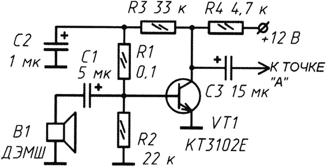
The output of this microphone amplifier on transistor VT1 should be connected in the break of the conductor running from regulating resistor R3 and capacitor C1.
In this case, elements R1 and C1 are removed from the original circuit (Fig. 1). Transistor VT1 is selected with a high gain and provides signal transfer of about 40 dB when used together with a DEMSh-type capsule.
Instead of the transistor indicated in the circuit, transistors KT373A, KT342V, KT3102A can be used. Electrolytic capacitors C1 – C3 in this circuit are used for any working voltage.
ASSEMBLY FEATURES
When soldering/assembling the IC, exercise caution; do not overheat the pins. The K174UN5 manufacturer recommends keeping the soldering time of a pin to no more than 3 s, with an interval of 10 s between soldering adjacent pins.
The length of conductors from the IC pins should be kept to a minimum — to reduce the effect of parasitic couplings.
“Modelist-Konstruktor” No. 7’2014, A. KASHKAROV
Recommend to read
 THE HEATER FOR THE ENGINE
Homemade heater for 220 volts was made from the bronze of the thermostat. Hacksaw for iron cut in half and sawn off side bottom outlet, throw everything inside. In the upper part drill...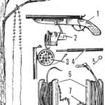 “SPINNING” FOR CUTTINGS
Increasingly in forestry a method of growing seedlings of valuable species of trees not from seeds but from cuttings. It is one thing to cut the stalk from the fruit tree — here a hand...
