I have been a long-time reader of the Modelist-Konstruktor magazine. In publications about homemade machinery I find a lot that is useful to me, and most importantly — my creative potential grows and I get the desire to design machinery myself.
I am a DIY builder with experience too. Over the past few years I have made three motor blocks for myself and my relatives. For cultivating a six-hundred-square-meter garden plot, especially one planted mostly with fruit and berry crops, these machines are very suitable. But if the plot is larger, their efficiency drops. You cannot do without a tractor here, even if it is a small one — a mini.
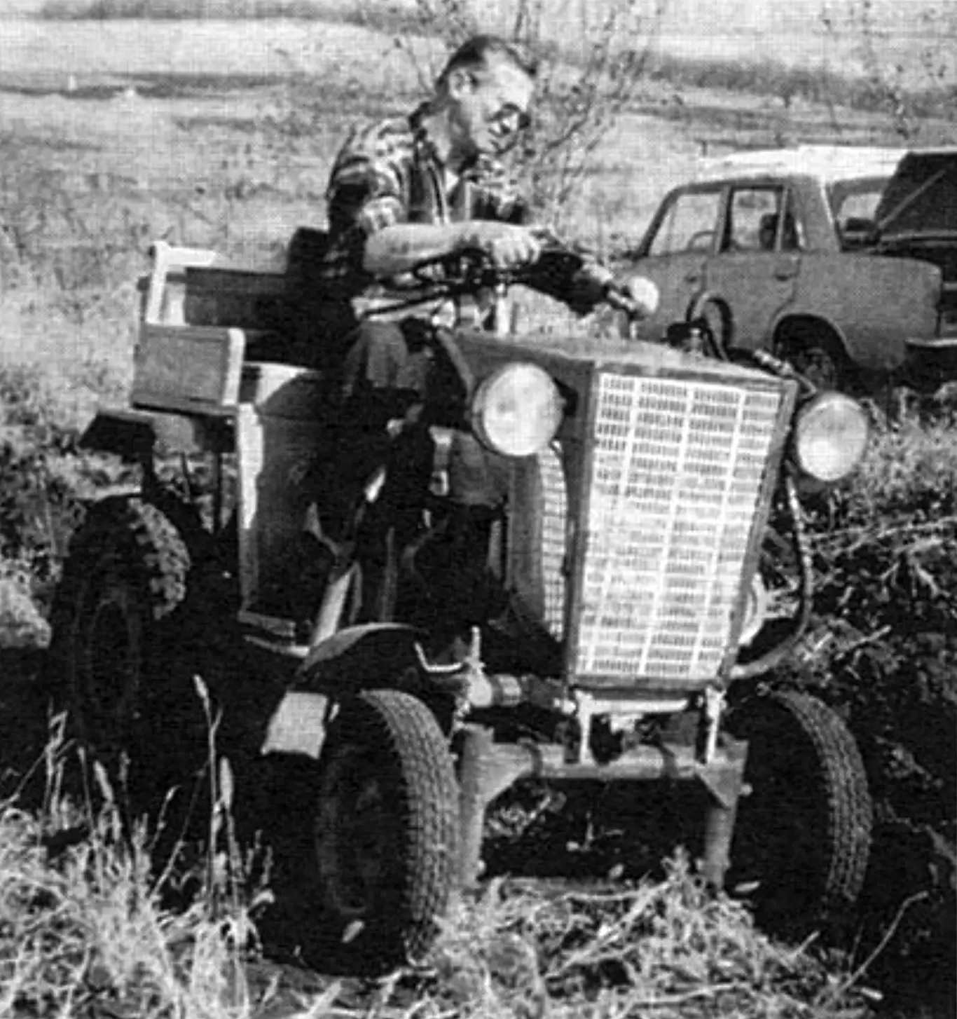
So, before taking a plot of land on a former abandoned collective-farm field, I decided to build — and built — a good helper for myself: a mini-tractor.
The mini-tractor described here is my second design. In the first model I placed the engine in the rear part of the frame so as to do without a driveshaft in the transmission. But the machine unexpectedly handled poorly, especially on climbs and under load. I tried putting counterweights at the front, but they made the design considerably heavier and helped little.
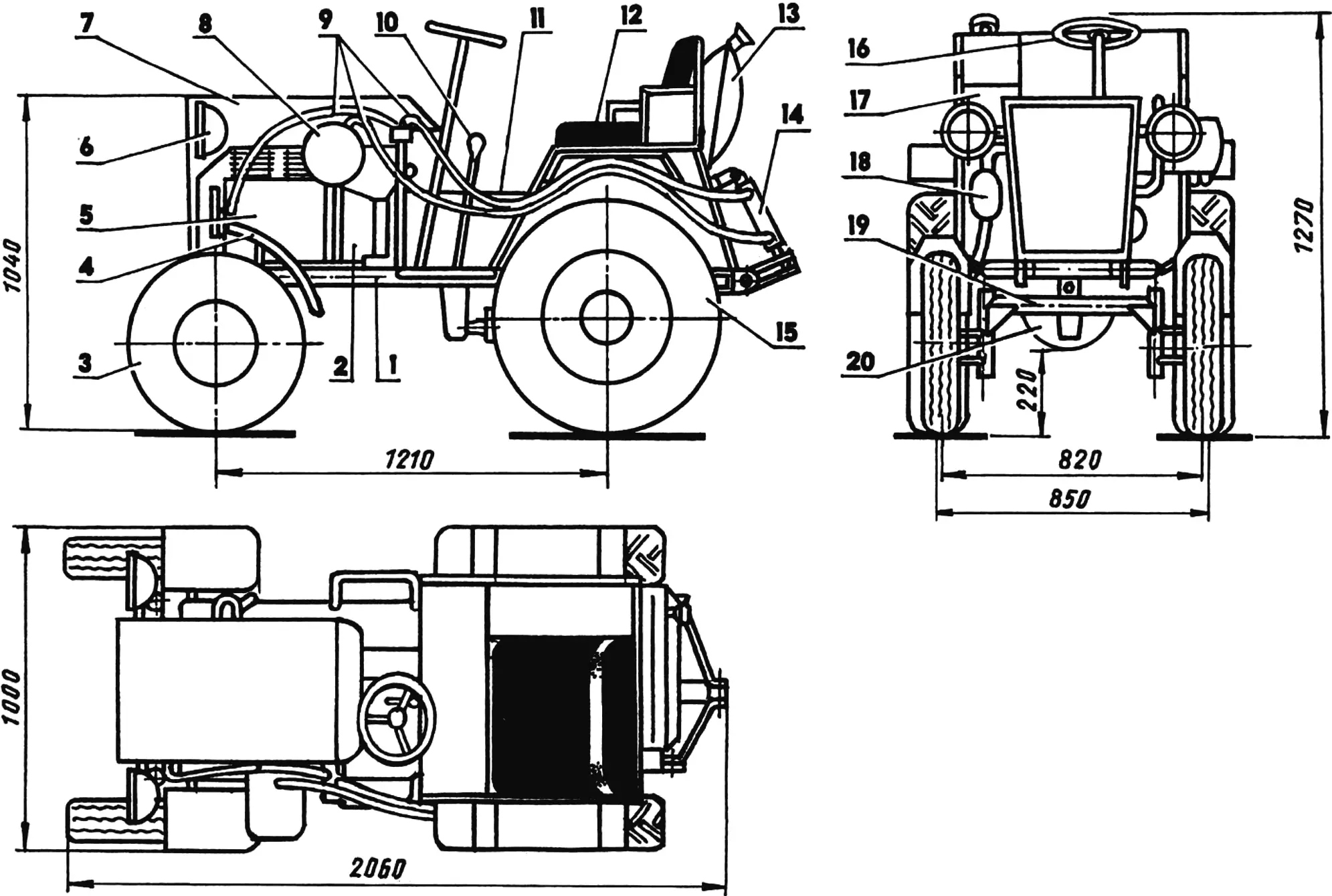
1 — frame; 2 — demultiplier (gearbox from a Ural motorcycle, modified); 3 — front steered wheel (from an S3D motor wheelchair, scooter tire, 2 pcs.); 4 — front fender (steel sheet s0.8, 2 pcs.); 5 — engine (UD-25, N = 14 hp, diesel); 6 — headlight (from agricultural machinery, 2 pcs.); 7 — hood (steel sheet s0.8); 8 — hydraulic system oil tank (from agricultural machinery, 4 l capacity); 9 — hydraulic system hoses (from agricultural machinery); 10 — speed shift lever; 11 — driveshaft cover; 12 — seat; 13 — fuel tank (20 l capacity); 14 — hydraulic cylinder (from agricultural machinery); 15 — rear driving wheel (from a Volga car, tires from a Niva car, 2 pcs.); 16 — steering wheel; 17 — tool box (from agricultural machinery); 18 — muffler; 19 — front axle (steel pipe Ø57); 20 — gearbox (from a Zaporozhets car)
In the end I decided to rebuild the mini-tractor and, after rearranging the assemblies, installed them in a classic layout. The result was a completely different, more successful design, and now the mini-tractor behaves excellently, which is why I decided to share its description with readers of the magazine I respect — DIY builders and machinery enthusiasts.
The main advantage of my mini-tractor design, in my opinion, is that it is assembled mainly from assemblies, mechanisms and units of serially produced machines, and therefore they are not hard to find. If necessary, when something breaks, spare parts for them are not so difficult to obtain.
The frame is of simple rectangular shape, welded. It consists of a pair of side members and two cross members: front and rear (all these elements are made from steel water pipes 57 mm in diameter).
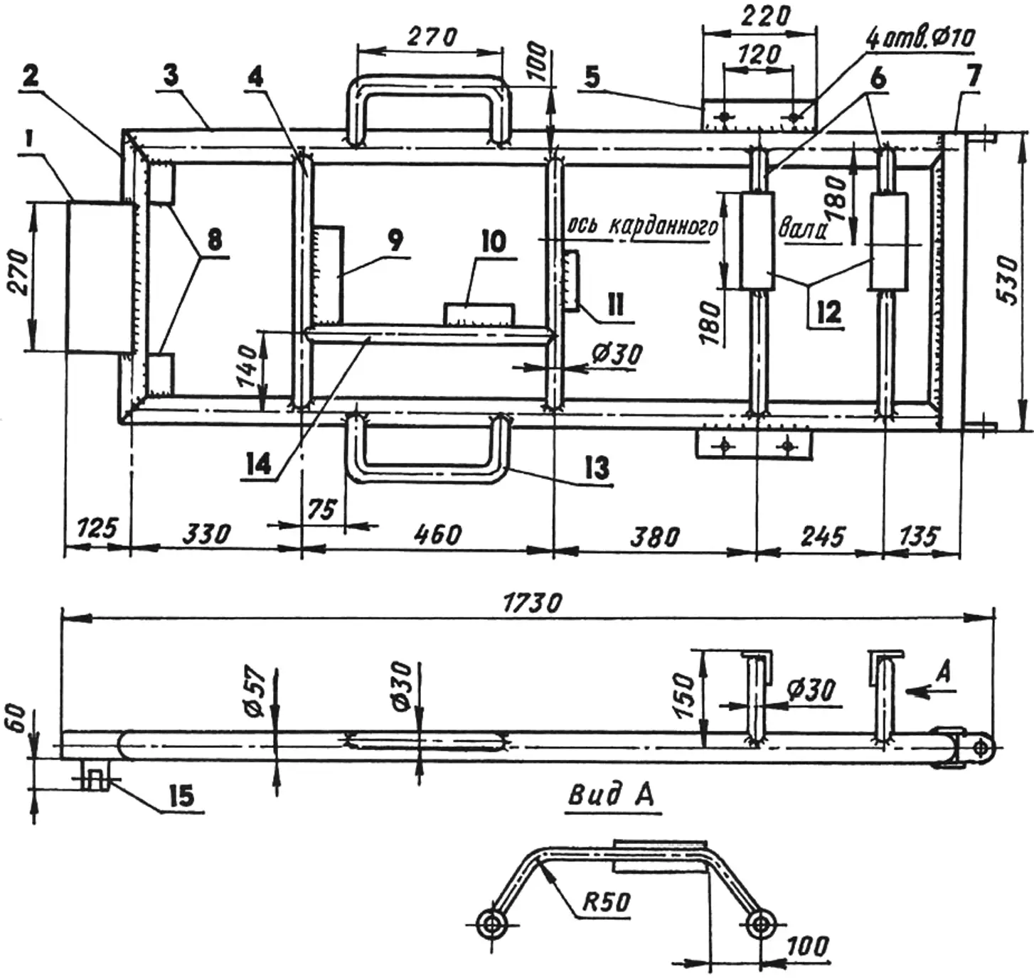
1 — front axle suspension bracket; 2 — front cross member (steel pipe Ø57); 3 — side member (steel pipe Ø57, 2 pcs.); 4 — cross tube (steel pipe Ø30, 2 pcs.); 5 — rear axle “boot” mounting bracket (steel sheet s5, 2 pcs.); 6 — driveshaft support arches (steel pipe Ø30); 7 — rear cross member (steel pipe Ø57 and channel No. 8); 8 — engine mounting support brackets (steel sheet s5); 9 — demultiplier mounting support bracket (steel sheet s5); 10 — gear shift lever support bracket (steel sheet s5); 11 — gearbox mounting bracket (steel sheet s5); 12 — driveshaft bracket support platforms (angle 80×80); 13 — footrest (steel pipe Ø30, 2 pcs.); 14 — cross brace (steel pipe 30); 15 — front axle mounting lug
A bracket with a lug (for connecting the front axle eye) is welded to the front cross member. The rear cross member is reinforced with channel No. 8 — it is slipped onto the pipe and welded to it. The ends of the channel are bent 90° backward — they form brackets for attaching the rods coming from the hydraulic hitch.
Two cross tubes are mounted between the side members in the front part of the frame, a longitudinal beam is placed between them, and engine mounting brackets are located in the corners of the frame. In the rear part of the frame, two arched stands with platforms are welded on — bearing housings for the driving sprocket shaft of the chain drive are mounted on them later.
Footrest arches bent from the same pipes as the cross tubes are welded to the outside of the side members in their middle part, and rear axle mounting brackets are welded in the rear part. Some additional elements, for example seat supports, instrument panel posts and others, I welded to the frame already during tractor assembly.
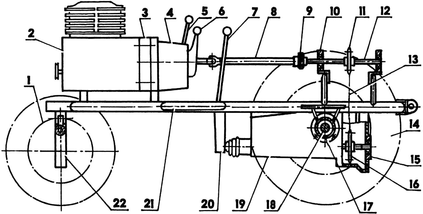
1 — front steered wheel (2 pcs.); 2 — engine; 3 — demultiplier-to-engine crankcase mounting adapter (steel strip 40×5); 4 — demultiplier; 5 — demultiplier gear shift lever; 6 — clutch control lever; 7 — gear shift lever; 8 — driveshaft (from agricultural machinery); 9 — elastic rubber coupling (from a Zhiguli car); 10 — housing with support bearing 80204 (from agricultural machinery) of the driving sprocket shaft (2 pcs.); 11 — driving sprocket (z = 24, from a Tula scooter); 12 — driving sprocket shaft (steel 45); 13 — drive chain (t = 12.7); 14 — rear driving wheel (2 pcs.); 15 — driving sprocket shaft support with bearing 80204 in housing (from agricultural machinery); 16 — driven sprocket (z = 38, from a Tula scooter); 17 — half-axle “boot” (from a Volga car, shortened, 2 pcs.); 18 — half-axle (from a Volga car, shortened, 2 pcs.); 19 — gearbox; 20 — gear shift lever bracket; 21 — frame; 22 — front axle
Holes in the brackets for mounting assemblies, mechanisms and units were also drilled mainly in place after their preliminary layout. And the layout, I must say, turned out so tight that the hydraulic system oil tank even had to be moved out from under the hood beyond the engine compartment.
The mini-tractor engine is a UD-25: two-cylinder, four-stroke, with forced air cooling, 14 hp. I used it without major modifications, since it had standard magneto and kick-starter. I only installed a Zhiguli pulley on the front end of the crankshaft to drive an NSH-32 oil pump for the hydraulic system of remote control of mounted implements. I modified the pulley bore. The V-belt drive is from a Zhiguli. I also used a Zhiguli muffler. At first, as usual on tractors, with the exhaust pipe upward. But the smoke went straight into my face. So I turned it over and routed the end of the pipe under the floor.
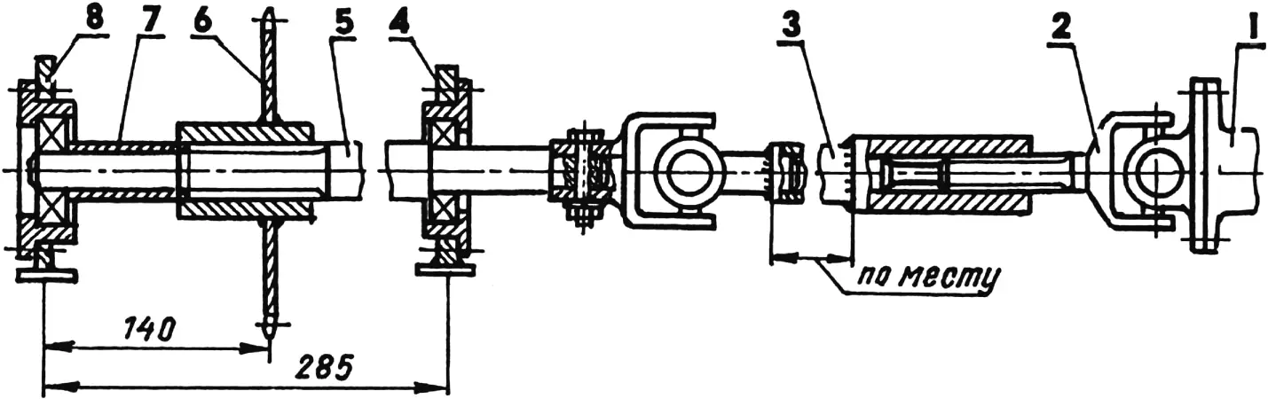
1 — demultiplier output shaft flange (from a Ural motorcycle); 2 — cardan joint with splined end (from agricultural machinery); 3 — main cardan shaft with splined sleeve (from agricultural machinery); 4 — front support with bearing 80304 in housing; 5 — driving sprocket splined shaft; 6 — driving sprocket; 7 — spacer sleeve; 8 — rear support with bearing 80304 in housing
The mini-tractor transmission is not quite ordinary — it has two gearboxes. The first one (together with the clutch) came from an old Ural motorcycle. The advantages of the Ural gearbox are its compactness and the fact that it is successfully combined with a two-disc clutch. I mated the gearbox to the engine using an adapter, fortunately the contours of the engine crankcase and gearbox almost coincide. The adapter is a ring bent from a steel strip 40×5 mm (joint welded). Studs M8 welded in place onto the ring protrude on both sides. One end of each stud goes into a mounting hole in the engine crankcase, the other into the gearbox, which serves as a demultiplier. For shifting speeds I installed a lever instead of a pedal.
In the Ural gearbox I left only two gears: first — as the working gear (it serves as an intermediate reducer) and fourth (direct, transmission gear) — it transmits torque from the engine through the cardan to the driving sprocket of the chain drive without changing the engine speed. The other gears (second and third) turned out to be simply unnecessary, since the second gearbox — from a Zaporozhets car — serves for changing speeds. A great advantage of this gearbox is also that it contains both the final drive and the differential in its crankcase.
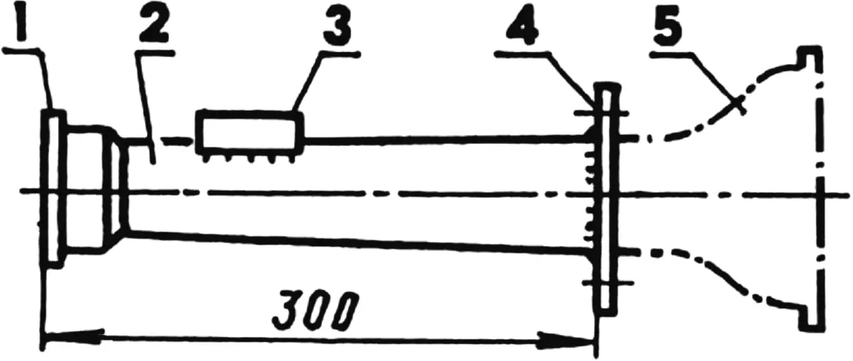
1 — half-axle bearing housing; 2 — “boot”; 3 — “boot”-to-frame mounting bracket; 4 — “boot” mounting flange to ZAZ gearbox; 5 — part of final drive crankcase to be cut off
The driveshaft is assembled. I took the rubber coupling from a Zhiguli car, and the other units, including housings with 80204 bearings, from various retired agricultural machinery. Between the arched supports of the frame, the driving (small) sprocket of the chain drive is mounted on a short shaft. Rotation from it is transmitted to the large driven sprocket mounted on the input shaft of the next gearbox. Both sprockets are from a Tula scooter: the small driving one (24 teeth) came from the gearbox secondary shaft; the large driven one (38 teeth) — from the rear wheel hub. The drive chain connecting the sprockets has a pitch of 12.7 mm. Chain tension is adjusted by shims under the bearing housings of the driving sprocket shaft. I will note a feature, or rather a requirement: I used only sealed bearings — with protective washers on both sides of series 8000 (those with seals — series 180000 — can also be used).
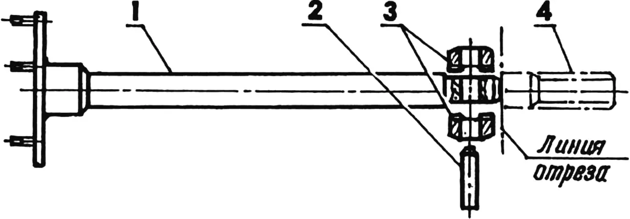
1 — half-axle with wheel mounting flange; 2 — pin (from a ZAZ car); 3 — keepers (from a ZAZ car); 4 — splined half-axle end to be cut off
The second gearbox of the mini-tractor (from a thirty-horsepower Zaporozhets ZAZ-965-M car) is located under the frame — it performs its standard function. Its input shaft had to be lengthened and the end placed in a 80202 bearing, the housing of which I secured in the rear cover of the clutch crankcase. From the second gearbox, rotation is transmitted to the rear driving wheels through half-axles. The half-axles are enclosed in “boots”. Both were taken from the rear axle of a Volga GAZ-24 car. The “boots” were shortened (the final drive crankcase was cut out of the axle), and flanges were welded to the ends for connection to the Zaporozhets gearbox. Holes in the flanges were drilled strictly according to the holes in the corresponding bosses of the gearbox. The half-axles were also shortened, and their ends were modified and made the same as those of ZAZ half-axles. I used pins and keepers from the Zaporozhets.
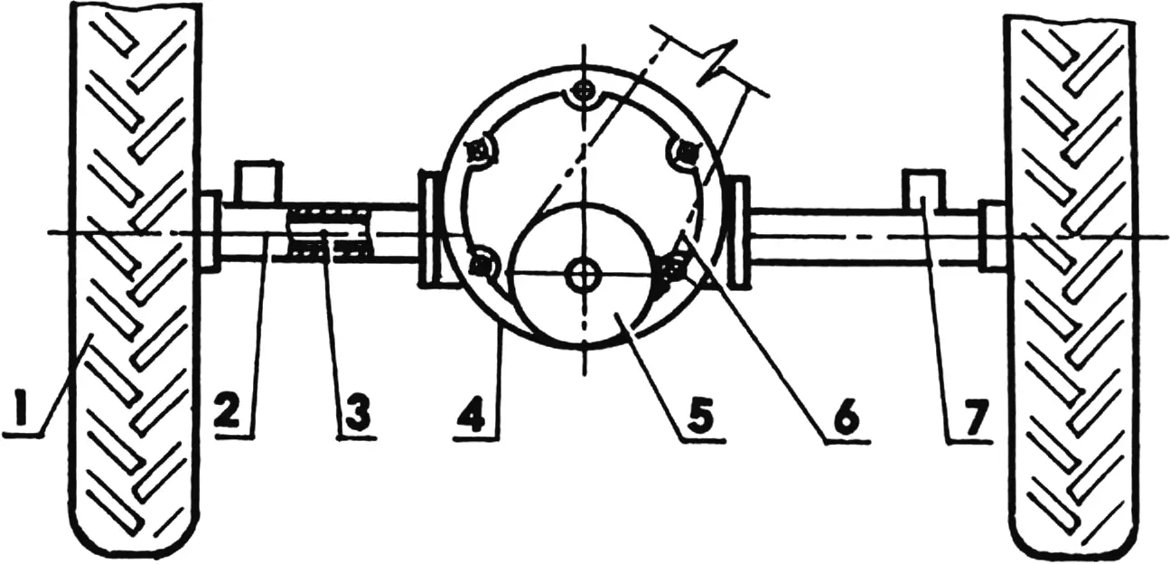
1 — rear wheel; 2 — half-axle “boot” (2 pcs.); 3 — half-axle (2 pcs.); 4 — gearbox with differential; 5 — driven sprocket; 6 — chain (t = 12.7); 7 — “boot”-to-frame mounting bracket
I also took the rear wheels from a Volga car. But since they are driving wheels, I “shod” them with M + S (mud and snow) tires with developed lugs (from a Niva car).
The front axle is homemade, welded in the shape of the letter P from the same pipes as the frame. The joints of the beam and uprights are reinforced with gussets. The hinged joint connecting the axle beam to the frame (eye from a cardan joint) is welded on top of the beam in its middle.
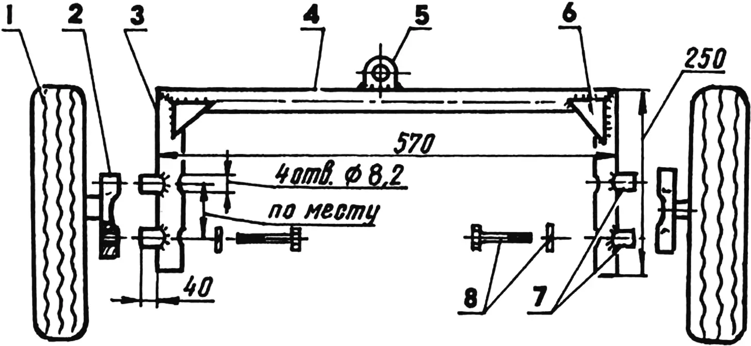
1 — front wheel (2 pcs.); 2 — steering knuckle (from an S3D motor wheelchair, 2 pcs.); 3 — upright (steel pipe Ø57, 2 pcs.); 4 — beam (steel pipe Ø57, 2 pcs.); 5 — axle-to-frame suspension bracket-eye; 6 — gusset (St3, sheet s3, 2 pcs.); 7 — spacer sleeves (pipe Ø30, 4 pcs.); 8 — M8 bolts (with spring washers) for mounting steering knuckles to axle (4 pcs.)
The front steering wheels together with spindles and steering knuckles were taken from a wheelchair. Scooter tires were fitted to the wheels. Wheel camber is adjusted by shims between the beam uprights and steering knuckles.
The brake system is from a Volga, but it acts only on the rear wheels, however that is quite enough.
The steering mechanism is from a Zhiguli, but it uses an angular reducer from some agricultural machine. The linkage scheme is ordinary, with two rods from a Volga car. One rod connects the steering arm to the left wheel knuckle lever. The other — the transverse rod — connects both levers and has a sleeve for adjusting wheel toe-in.
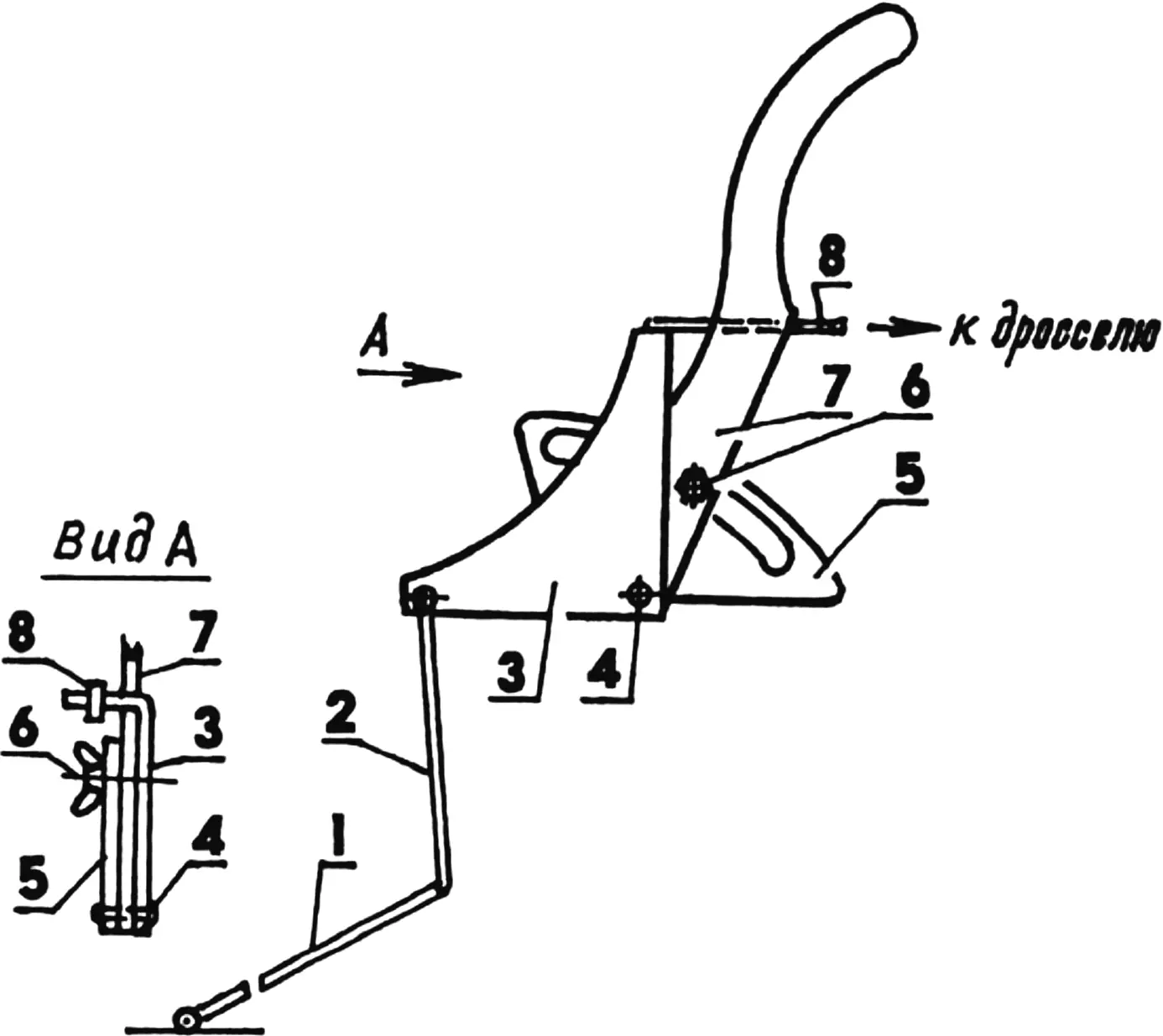
1 — accelerator pedal (from a Volga car); 2 — lever rod; 3 — foot throttle control lever; 4 — common lever axis; 5 — fixed sector (from a Moskvich-400 car); 6 — hand lever lock bolt; 7 — hand throttle control lever (from a Moskvich-400 car); 8 — throttle rod
The instrument panel has a speedometer, engine oil pressure gauge, and ignition switch.
The fuel tank holds about 20 l of diesel fuel. I pour about 4 l of oil into the hydraulic system tank. The hydraulic system is used to raise and lower the hitch with soil-working implements. For plowing I use a single-share plow, and for inter-row cultivation of crops — two hillers.
Modelist-Konstruktor No. 4’2004, V. KONOVALOV
Recommend to read
 THE PACK, NOT THE BASKET
Usually writing or computer table is a basket for unwanted papers and other debris. And how without it? In my opinion, much easier and more practical to have on hand for these purposes,... SU-17: FIGHTER AND BOMBER
Projects and experienced first instances of jet aircraft with variable geometry wings appeared during the Second world war: in our country the project of this aircraft was developed V....
