From the transfer box the rotation is transmitted to axles of the drive wheels, made of driveshafts GAZ-69. Each rod is attached to the lower part on the box-shaped frame construction reinforced corner 75X75 mm with two placed together (between u-joint and are installed on the end of axle flange) self-centering bearings # 1680206С17. The same bearings are taken from a discarded straw walkers of the combine harvester “Niva”, used also to attach the PTO shaft (on top of the spars, box-shaped part of the frame design).
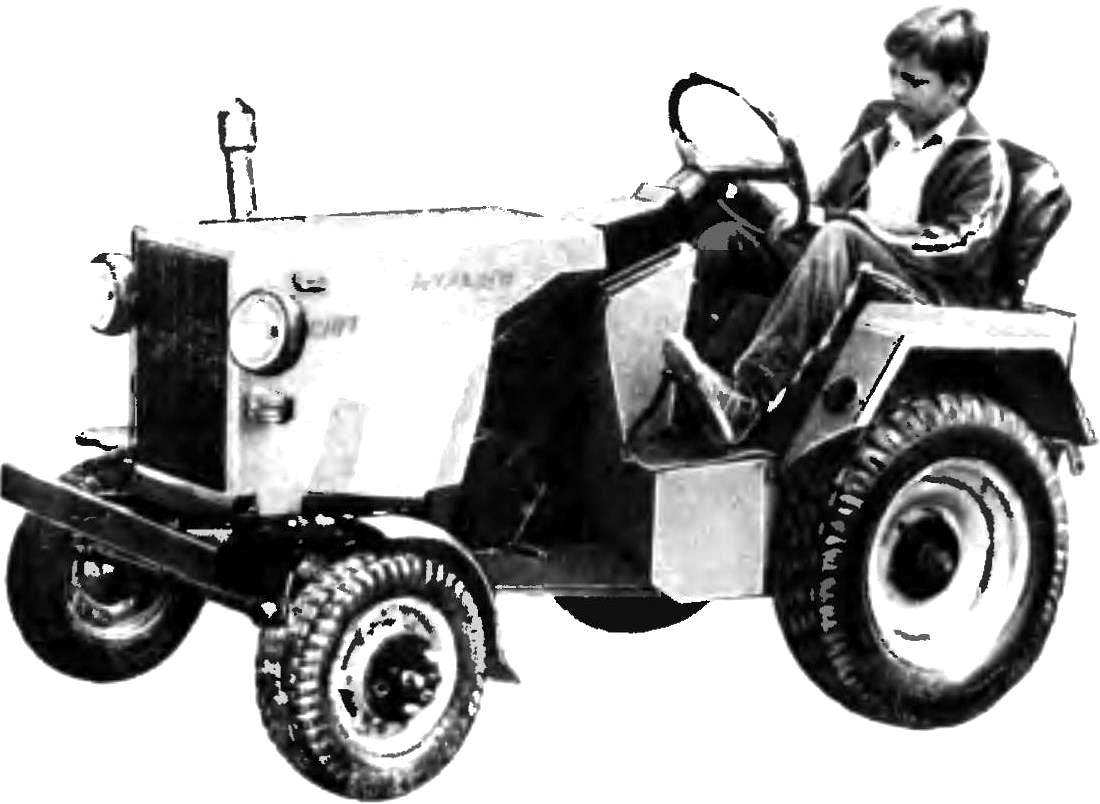
Fig. 1. The layout of the mini-tractor “Ant”:
1 — turn indicator, 2 — headlight, 3 — the hood, 4 — engine, 5 — air filter 6 — clutch pedal 7 — shift lever, 8 — steering column 9 — the lever of expedited transfer, 10 — rear fender, 11 — seat 12 — lever suspension, 13 — reversing lamp, 14 — suspension, 15 — front wheel, 16 — steering wheel 17 — reflector, 18 — decorative grille, 19 — bumper, 20 — tie-rod, 21 — front wheel, 22 — towing ring, 23 — front wing, 24 and the splash guard 25 — brake pedal 26 — polik, 27 — gas pedal 28, the lever reverse, a 29 — lever dual, 30 — the lever of blocking of the rear wheels, 31 — brake light and direction indicators, 32 casing shaft of the PTO, 33 — muffler.
Fig. 2. Kinematic scheme of transmission indicating center distance of shafts:
1 — driven (front) wheels, 2 — engine “Tula 200”, 3 — gear shift GAZ-21, 4 — star, power take-off (removable) on the intermediate shaft, 5 — speed transfer case GAZ-69 with the brake drum and hub wheel locks, 6 — lead (rear) wheels.
Fig. 3. The attachment of the drive wheel (bottom view):
1 — drive axle of the drive wheel (shortened to 350 mm cardan shaft GAZ-69), 2 — upper box-shaped part of the frame, 3 — self-aligning bearings with tension sleeves (from the straw walkers “Fields”) No. 1680206С17, 4 — bracket (area 75x75mm welded to the top of the box-shaped part of the frame), 5 disc wheels, 6 — flange with hub welded to the wheel disc, 7 — washer 8 — nut M25, 9 — flats, 10 — bolt M10.
Fig. 4. Front axle:
1 — bushing front axle, 2 — cross beam, reinforced with ribs, 3 — front the front wheel axle, 4 — “glass” bracket-front fender, 5 — screw M6, 6 — round nut M27 (4 PCs), 7 — axle left wheel welded to the shaft of the strut and the lever swivel pin 8 — axis right wheel welded to the shaft of the strut and the lever of a steering trapeze.
Fig. 5. Steering:
1 — the steering wheel. 2 — steering shaft 3 — cross, 4 — steering gear 5 — lever swivel pin 6 — fry the steering mechanism, 7 — tie-rod 8 tie rod end GAZ-69 (GAZ-21), 9 — the lever of a steering trapeze, 10 — front axis of the front wheel 11 is the driven (front) wheel.
As the leading applied (given their availability, the time factor is important) wheel 5,50-16 inches from the agricultural model L-182. For fasteners, it is advisable to use method, well known to all the tinkerers of the vehicle. It is necessary to make the shaft “flats” — flat pad, a bit stachiw the end of the shaft. In this case, the “flatted” it is desirable to carry on the plot thread from the M25, where the site will reach a width of 20 mm, and further to 45 mm along the shaft with the “gathering”. The wheel disc is welded circumferentially to the flange thickness of 15 mm, with hub 30 mm, the inner diameter of which is located the protrusion, analogous to the “flats” on the shaft. The wheel is placed on the thus prepared shaft and tighten the nut M25 with washer 10 mm thick.
Good mini-tractor must be easy to use, reliable steering. The “Ant” beam front axle home-made, made of thick-walled pipe, reinforced welded ribs. And the details of the steering mechanism borrowed from the car “Moskvich-400”. The rack axis of the front wheels is mounted on thrust ball bearings, which contributes to easy rotation of the wheels. On top of each post — “glass” with welded thereto a front fender bracket and the mounting hole in which the threaded screw M6. The front wheels “Ant” is taken from scooter “Tula 200” (model K-82: 4,00—10 inches). Steering shaft (total length 1200 mm) — from the GAZ-51.
Frame mini-tractor has a trapezoidal (front) and a box (for installation transfer box GAZ-69 and the leading axle) parts. The design of it is welded. Spars, front and rear cross beams for attached devices is made of a channel 100X80 mm, while the rest of the frame from the corner 75X75 mm. On the front crossmember welded gusset plate of 10 mm steel sheet. They made holes with a diameter of 18 mm under the axle to secure the front axle.
Fig. 6. Frame mini-tractor:
1 — longeron (channel 100Х80), 2 — cross front (channel 100X80), 3 — gusset plate (for fastening the front axle), 4 — middle cross-member (area 75X75), 5 — box-shaped part of the frame 6 — bracket for additional bearing (area 75X75), 7 — kosina, 8 — beam for mounted implements, 9 — sleeve with an inner diameter of 24 mm, 10 — rear crossmember (channel 100X80).
Fig. 7. Location of parts and on the frame (hood removed).
Fig. 8. Design of the mechanical actuator portion (with the removed lock):
1 — sprocket Z=16, 2 — arm drive attachment, 3 — Bush slide bearing, 4 — chain with a pitch of 19,05 mm, 5 — thrust (rod diameter 10 mm, length of the chain to the lever 450 mm), 6 — major axis of the actuator hitch, 7 — Cam, 8 — rib, 9 — cosina, 10 — beam for mounted implements, 11 — arm, 12 — front (length 500 mm), 13 — bracket for mounting to the tailgate.
Fig. 9. The actuators of switching speeds:
1 — sprocket Z=19 (from the rear sleeve sports bike), 2 — sprocket Z=13 (children’s bike), 3 — bearings, 4 — arm low (high) transmission, 5 — lever reversing (reverse), 6 — gear shift GAZ-21.
The location of the units and parts of tractors on the frame is clear from the figure, where “Ant” is shown with an unfolded hood. Ahead of the battery, above it on a T-shaped (front) and l-shaped brackets fixed firmly to the tank. The engine is mounted on racks or brackets.
Lining made from steel sheet 1.5 mm thick and painted with automotive enamels.
Great attention is paid to the electrical mini-tractor. Provides lighting front and rear, turn signal, beep. On the control panel to set the indicator light neutral gear, turn on high and low beam, charging, the pointer of the brakes.
Technical characteristics of “Ant”
Overall dimensions, mm: 2610Х1080Х1350
Base, mm: 1300
Track, mm: 950
Ground clearance mm: 280
Weight (without trailers and mounted implements), kg: 400
Engine: single cylinder, two-stroke; “Tula 200”
Engine power, HP: 14
Transport speed, max, km/h: 40
Operating speed, minimal, km/h 2.5
N. KOCHETOV, our special. Q.
Recommend to read GREENHOUSE DOME Gymnastic Hoop, four boards and plastic film — all that is needed for the manufacture of a simple greenhouse. Wraps cut in half and secured crosswise of the drilled holes of the frame of... IRREPLACEABLE IN THE FALL A horizontal strap, with teeth so attached to the middle of the handle — that, in fact, the whole design is as old as the world agricultural implement, without which no gardener-lover or... 
 What does a mini-tractor “Ant”? What lies behind the pleasing to the eye successful?