I was confirmed in my decision to build a walk-behind tractor after I read the article “Vyatich” (“M-K” No. 7, 1981). However, the design proposed by the magazine, despite all its advantages, did not satisfy everything. And first of all, I didn’t like the chain transmission: I wanted to make the transmission more compact, thereby reducing the height of the machine and at the same time increasing the safety of working with it. An enclosed gearbox would be best, but making gears at home is not easy. This is where the idea arose to assemble a transmission from ready-made gears, which go on sale as spare parts for the Elektron scooter engine. This should be discussed in a little more detail.
To make the gearbox, I needed the following parts of the V-150 M engine: a crankcase, four gears, three chain sprockets and an additional gearbox shaft. I sawed the crankcase in half and removed the gearshift mechanism and kickstarter from its right half. I also cut off the crank chamber from the gearbox, and carefully filed the remaining part of the cover. In place of the kickstarter, I pressed a housing made of duralumin alloy. It is advisable to additionally fix the latter in some way: I had the opportunity to use argon electric welding, but this is not difficult to do with the help of a regular pin.
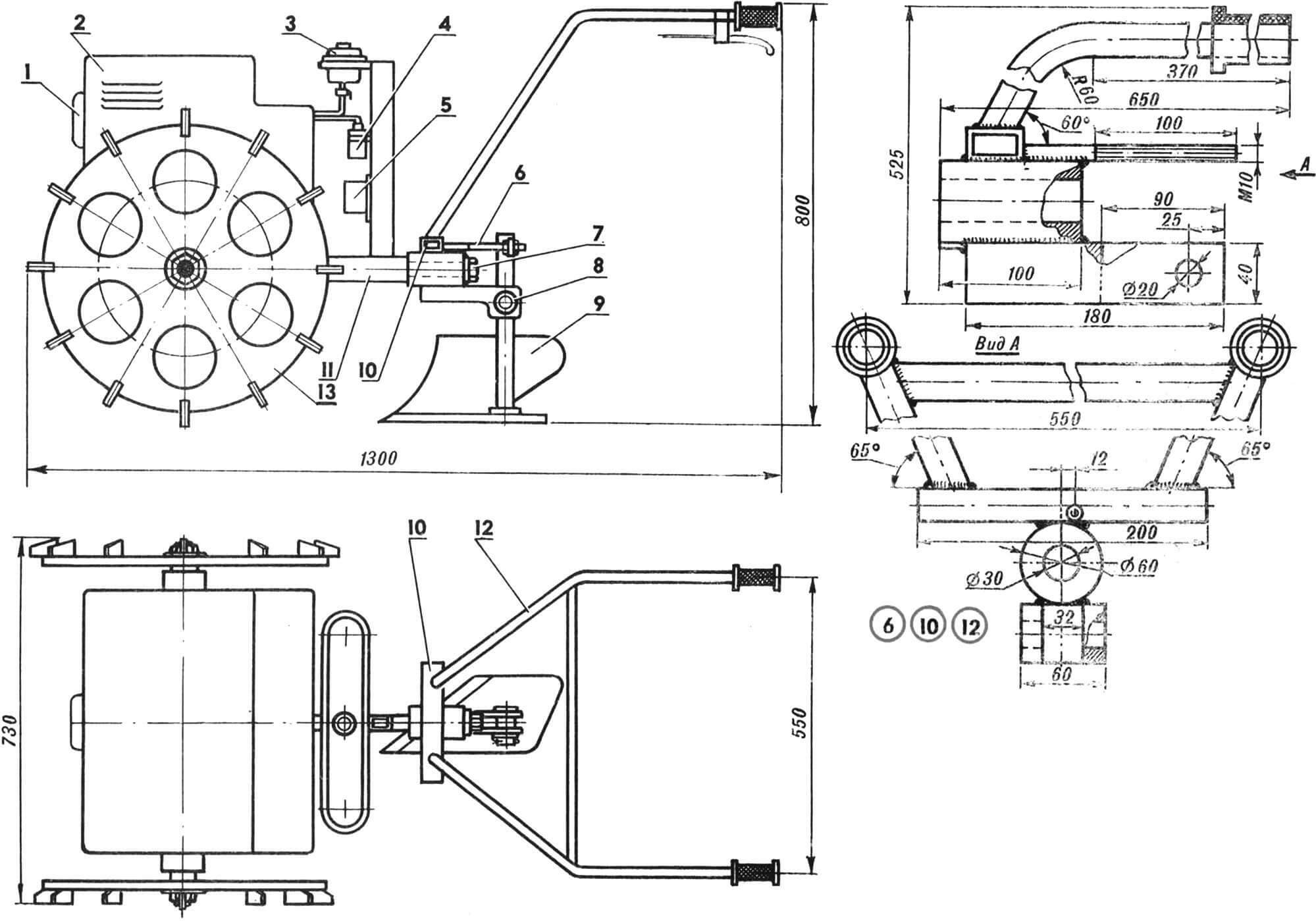
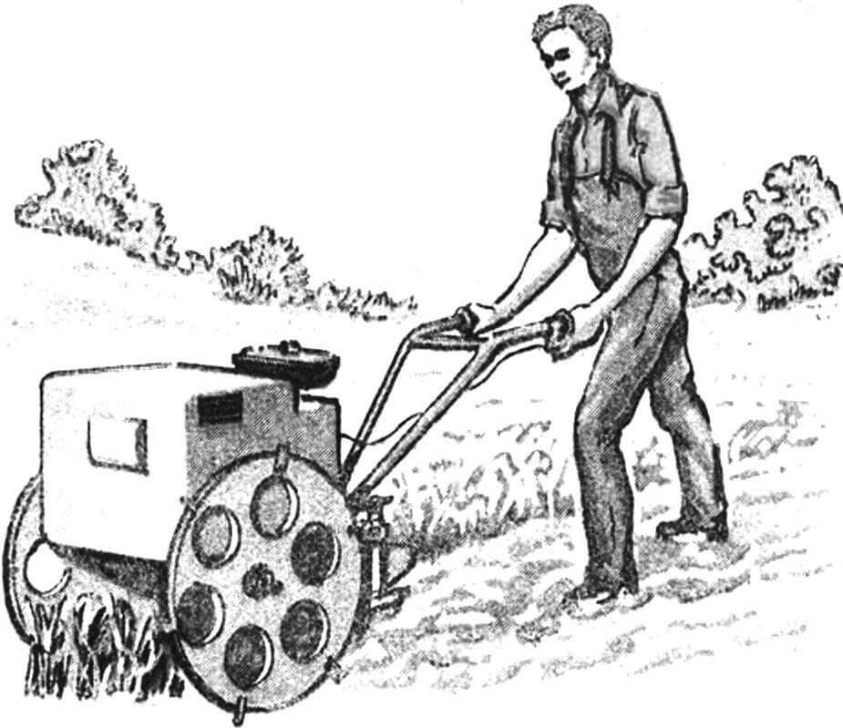
1 – engine, 2 – casing, 3 – gas tank, 4 – ignition coil, 5 – switch, 6 – pin for fixing the angle of inclination of the working element (not shown in the top view), 7 – M16 bolt, 8 – mounting axis of the working element, 9 — working body (plow), 10 — holder, 11 — frame, 12 — carrier with control handles, 13 — wheel with lugs.
From the left half of the crankcase I cut out a flange for the axle and used it as a bearing axle box for the right running wheel of the walk-behind tractor. In principle, this part is not difficult to machine, but I had an extra old crankcase, and I did not give up the suitable element.
The left gearbox cover was also made from the crankcase of the V-150 M engine. I had to additionally machine one part – a duralumin bushing. Its outer diameter corresponds to the diameter of the crank chamber (Ø 105 mm) and must be processed in such a way as to ensure a press fit. The inner diameter of the bushing is determined by the dimensions of the engine output shaft shank.
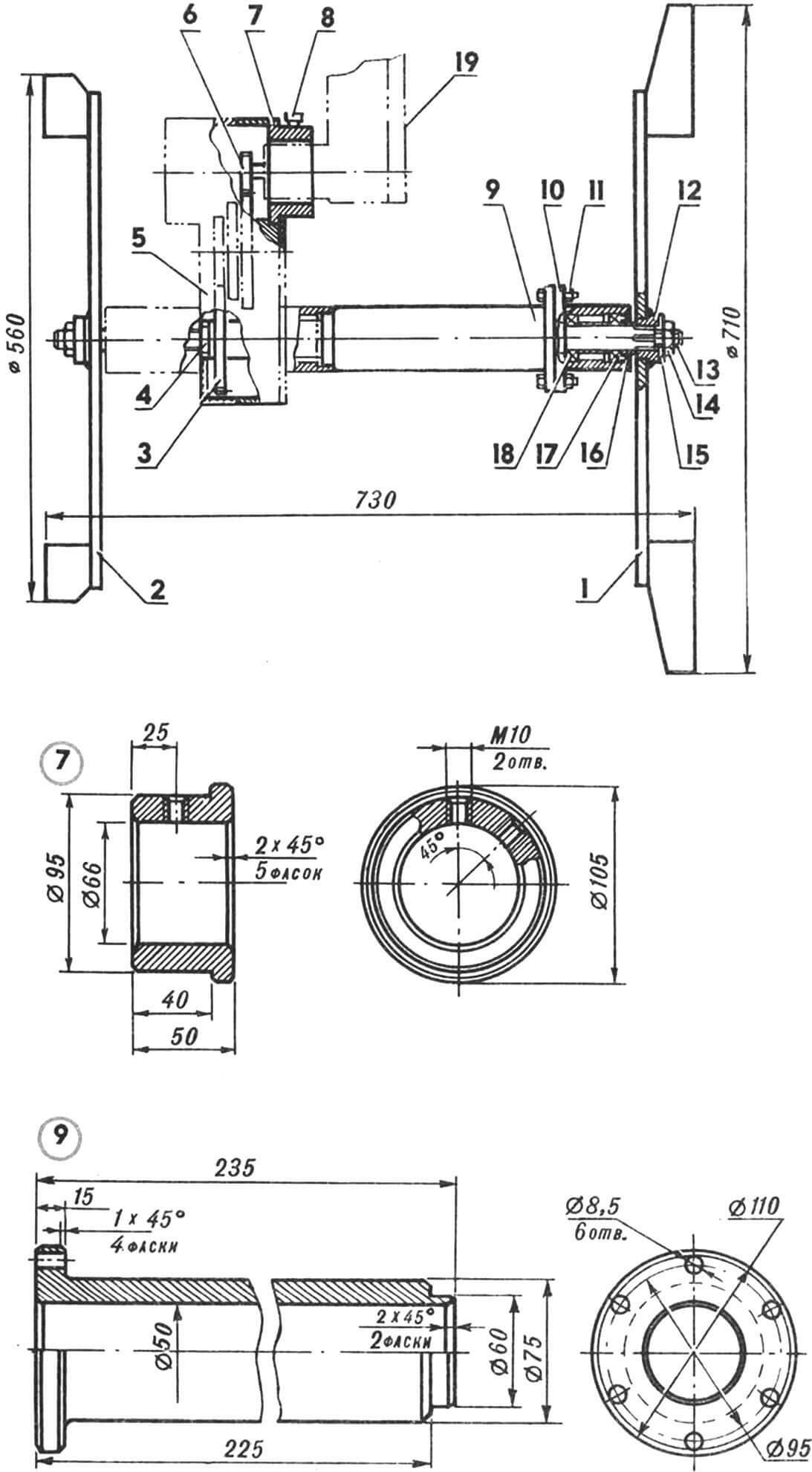
1 – right wheel, 2 – left wheel, 3 – first gear gear, 4 – drive shaft, 5 – gearbox, 6 – drive gear, 7 – bushing, 8 – M10 locking screw, 9 – drive shaft housing, 10 – flange axle box, 11 – nut and bolt M8, 12 – splined bushing, 13 – shaft, 14 – nut M14, 15 – washer, 16 – oil seal, 17, 18 – bearings, 19 – engine.
Before starting to manufacture the drive shaft of the walk-behind tractor, I disassembled the gearbox, removed from it the spider and the gears of the second and third gears. I left the first gear in its place and additionally secured it with electric welding. Then he took two secondary shafts, ground off a collar from one of them – free, without a gear, put them on a Ø 22 mm rod and welded it to the latter from the inside. As a result, the shaft acquired the appearance shown in Figure 3.
I first cut off the teeth of the engine output shaft sprocket, and then welded the drive gear to it, fitting it in place to the intermediate shaft gear. Thus, I got a gear, fixed with a spline connection on the shaft of the V-1 50M engine instead of a chain sprocket.
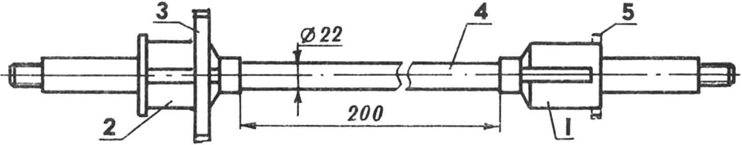
1,2 – cantilever parts of the shaft (from the secondary shafts of the V-150M gearbox), 3 – gear (from the first gear gear of the V-150M), 4 – middle part of the shaft (rod Ø22 mm), 5 – cut-off collar.
The engine itself was slightly modified: the gear shift lever was welded on, the kickstarter was made removable. The motor and gearbox are fixed relative to each other using one M10 screw.
I cut the running wheels from a steel sheet 8 mm thick and welded 12 lugs to each. In order not to make hubs with splines for the shaft myself, I used chain sprockets from the same “Electron”, attaching them to the wheel rims by electric welding.
The frame was made from water pipes. The holder is secured to the main beam with an M16 bolt, for which a pin with a blind threaded hole is welded into the main frame spar.
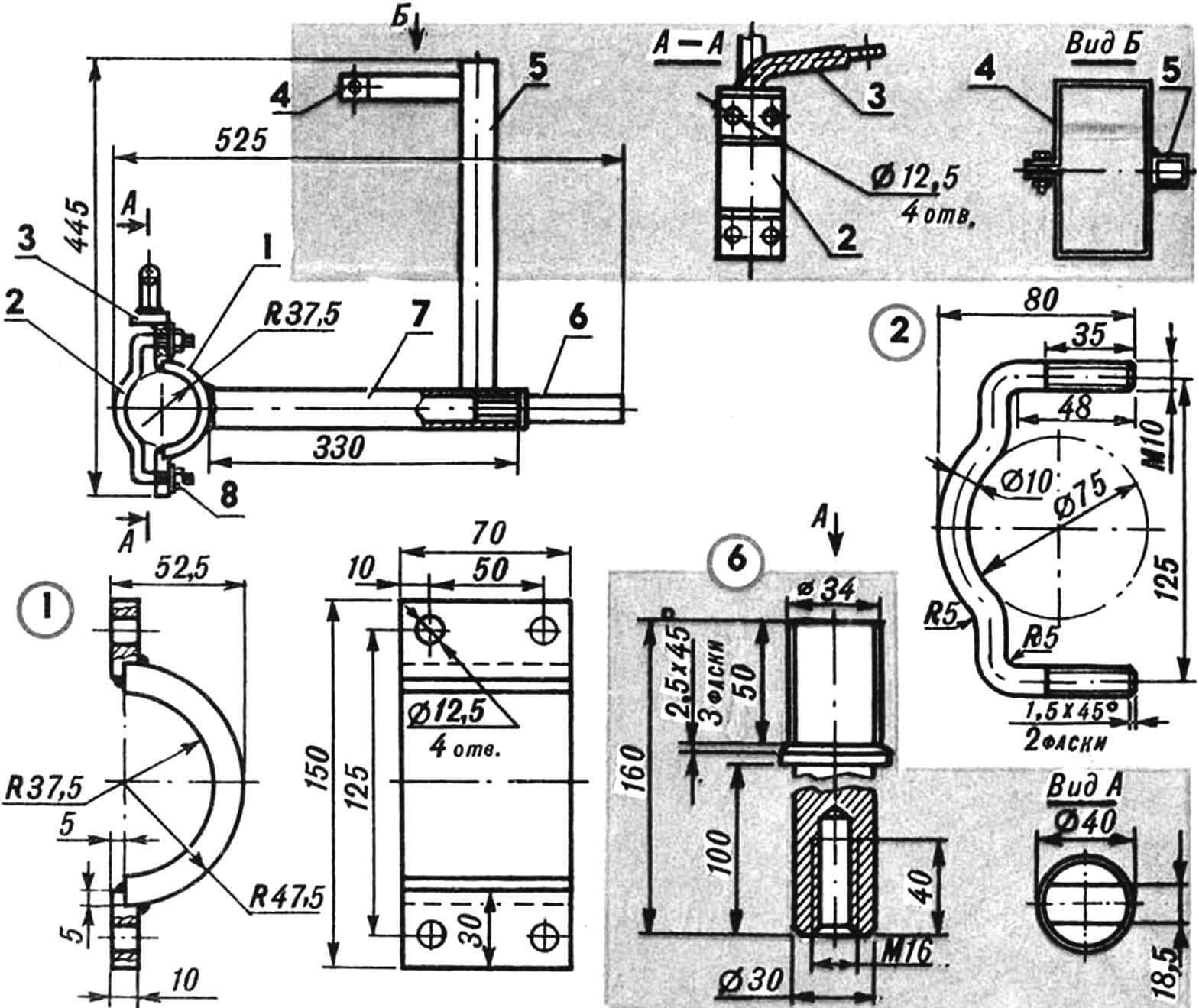
1 — bracket, 2 — clamp (2 pcs.), 3 — engine mounting bracket, 4 — gas tank mounting clamp, 5 — stand, 6 — pin, 7 — longitudinal member, 8 — M10 nut.
An old car oil tank served as a gas tank. The control handles are from a motor scooter.
The working body (usually a plow) is installed in the holder fork, and its angle of inclination is adjusted with a pin. The holder itself, together with the control handles and the plow, can rotate around the pin of the longitudinal frame spar – this provides control of the walk-behind tractor and compensates for unevenness in the field.
I have been using the walk-behind tractor for more than five years, and in all that time there have been practically no serious failures. At the same time, I believe that the engine’s capabilities are far from being fully exhausted. I plan to install a power take-off shaft to drive a mounted mower, and also use removable wheels from a motorcycle, which will make it easy to transform the walk-behind tractor into a universal vehicle.
V. SALOV
Recommend to read
 UNIVERSAL SCHEME
"No, this simply cannot be!" — these or similar words — "the standard reaction" athletes of any rank. And calls it the mention of flight models, three years under construction in our... “MOLE” TO HELP
Aircraft mechanic M. A. Masters is one of the remarkable constellation of Amateur designers, which has always been proud of the Udmurt ground. He has such serious works as Delta - and...
