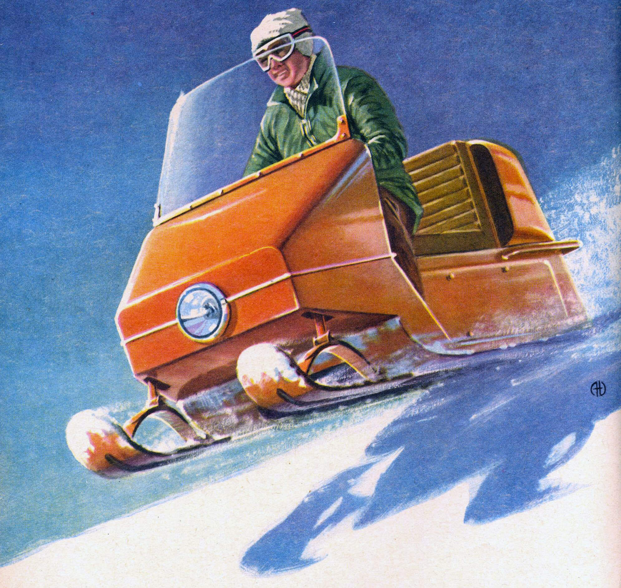
One or two tracks at the back, two skis at the front, a seat for two passengers – this is what motorcars look like – the machines that are now making a triumphal march around the world. They are ridden even in countries where snow is rare, for example in Italy. Motor sleds have almost completely replaced snowmobiles as a means of winter transport; they are more economical, more sustainable, safer.
The time has come for the leaders of auto clubs at young technician stations, and simply amateur construction enthusiasts, to turn their attention to motorcycle art. A motorcycle engine is not in short supply; It is quite possible to make skis and tracks in a small workshop.
The motorcars that will be discussed here, for all their simplicity, can serve not only for entertainment and sports; they are a reliable means of transportation over short distances wherever snow cover persists for a long time. According to the design scheme, the “Snowflake” is similar to the currently most common types of motor guns – such, for example, as the domestic machines of the Gorky Polytechnic Institute, or foreign ones – “Johnson”, “Evinrud”, etc.
This design, with some modifications, was borrowed from the Czechoslovakian magazine “Veda and Tekhnika Molodezhi”.
The Snowflake, the general view of which is shown in Figure 1, is a machine resembling a regular motor scooter with one driving track at the rear and two steerable skis at the front. The skis, interconnected with each other, are controlled by a car or motorcycle-type steering wheel. The caterpillar is driven by a motorcycle or scooter engine with a power of at least 5.0 – 6.0 liters. With. If an amateur who decides to build a snowmobile has the opportunity to choose, preference should be given to an engine that has a forced cooling system from a fan (for example, VP-150 M, Tula-200, ChZ-175 motorcycle engines, and M-175 motorcycle engines). 1-M – from the first releases of a wheelchair, etc.).
We consider it our duty to warn amateurs against trying to use low-power engines – for example, from the Druzhba chain saw and the like: they will not pull the Snowflake.
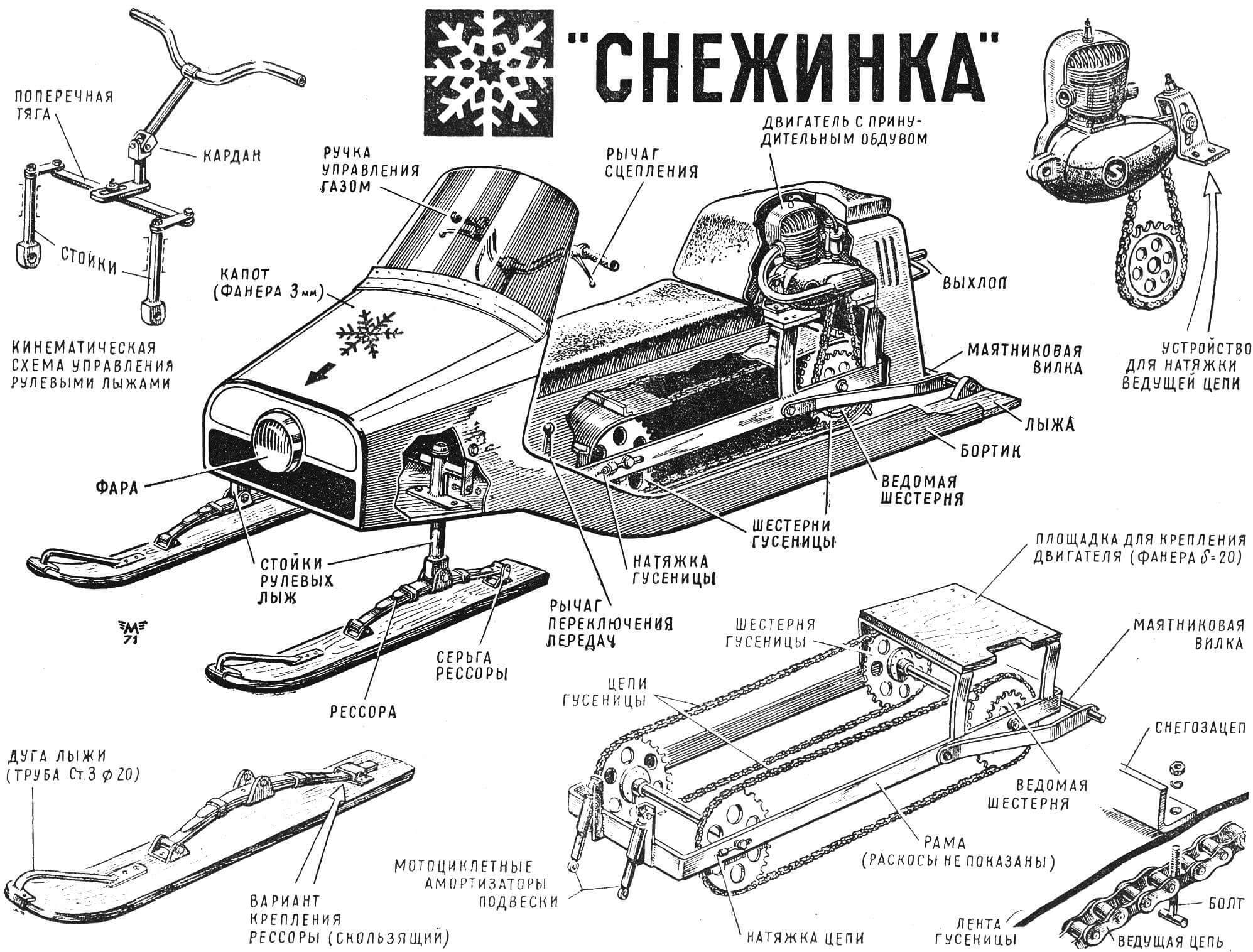
Motor skids “Snezhinka” structurally consist of two independent parts (Fig. 2): a wooden body A, which has runners on the sides, and a metal chassis D, hinged to the body on levers 11 and motorcycle-type shock absorbers 1. Mounted on the chassis: a drive shaft with three gears, designated respectively by numbers 9 and 10; driven (front) shaft 5 with two teeth 6. Gears 6 and 9 are the same diameter and have the same number of teeth for a motorcycle chain with a pitch of 1/2″. The drive shaft is installed in fixed bearings, preferably ball bearings, the driven shaft has a device for tensioning the chain, and with it the drive track. Such gears can be selected from motorcycle parts with a diameter of 220-260 mm available in stores.
The motorart body is manufactured in the following sequence. First, the frame of the side walls is assembled from oak or ash beams with a cross section of 35X25 mm in accordance with drawing A (see Fig. 2). In the front part, these bars are fitted to plates cut along the contour shown in position A. It is recommended to glue the frame with epoxy or casein glue. The side walls are connected to each other by a vertical frame, forming a backrest for the driver and at the same time the front wall of the engine compartment. Then parts B and C are cut out of waterproof plywood 10 mm thick, which are glued into place and pressed into place with screws. The frame of the side walls is sheathed on the outside with plywood 5 mm thick and also pressed in with screws 15 mm long. When screwing in screws, you must first drill Ø 2 mm holes according to the markings, otherwise the screw may break or the block may split.
After this, in accordance with the contour G, parts of the support runners are cut out of plywood 4-5 mm thick. As can be seen from the drawing, their front part is bent upward, like the toe of a ski. This rounding is obtained as a result of sequential gluing of blanks one on top of the other on the lower part of the body with pressing in with 20X3 screws and nails 15 mm long. The lower (sliding) part of the runners must be sheathed with sheet steel 0.6-0.8 mm thick – to improve the sliding of the sled on the snow surface. A safety bar is placed along the outer edge of the runners using epoxy glue and screws, which simultaneously serves as a stiffening rib for the platform on which the driver places his foot.
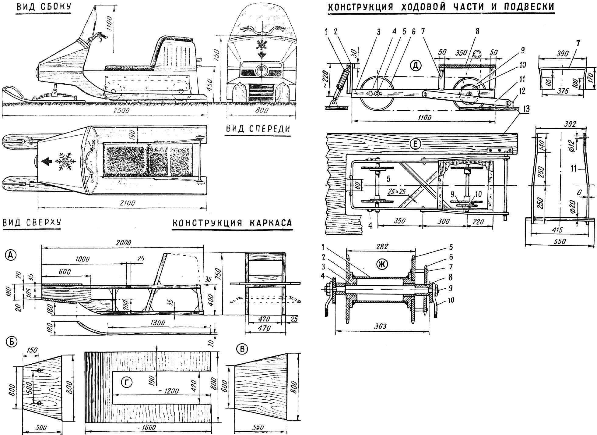
A — body side panel frame; B and C – frame details; G – runners; D — chassis, side view; E — chassis, top view: 1 — front suspension shock absorber, 2 — shock absorber bracket, 3 — chassis frame (“carriage”), 4 — chain tension, 5 — axis of the front track gear unit, 6 — front track gear, 7 — engine mounting racks, 8 — engine mounting platform, 9 — rear track gear, 10 — driven gear of the main drive, 11 — pendulum fork, 12 — suspension eye of the pendulum fork, 13 — skid; G – drive shaft assembly: 1 – thin-walled steel pipe, 2 – flange, 3 – bronze bushing, 4 – chassis frame, 5 – track gear, 6 – driven gear, 7 – driven gear mounting bolt, 8 – spacer sleeve, 9 – axle nut, 10 – chain tension.
Having completed the complete assembly of the body, you should cover it on both sides with hot drying oil or primer No. 138 and begin manufacturing the chassis (see Fig. 2). Chassis frame 3 is made of a 60X6 mm steel strip, which is bent in accordance with the drawing and welded with gas or electric welding. In the middle part of the frame, a cross-shaped spacer from a 25X25 steel angle is welded (the angle pieces are placed “back to back” to each other). The necessary holes are drilled in the frame and grooves are sawed for tensioning the driven shaft 5. The brackets in the front part of the frame are used to mount motorcycle-type shock absorbers, on which the frame is suspended from the body, and in the rear there is a bridge for mounting the engine. Angles with Ø 8 mm holes are used to tension the driven shaft. The length of the shock absorbers must be selected experimentally by changing the shape and height of the square that secures the lower eye of the shock absorber.
The design of the shafts on which the driven and driving gears rotate is shown in Figure G. In the simplest version, these shafts rotate in bronze bushings. But, of course, it is more expedient to use ball bearings by making the corresponding cups (clips) on a lathe.
The last stage is the manufacture of the pendulum fork on which the chassis is suspended. The pendulum fork in combination with the front shock absorber helps dampen the shocks and shocks experienced by the machine when driving on uneven terrain. Therefore, it must be carefully executed and reliably welded to the suspension axle.
An engine for a motorbike must have a clutch mechanism and a gearbox. It is better if it is four-speed – this will allow you to quickly select the most advantageous gear ratio without resorting to replacing the final drive gears.
The resistance of the engine, especially when starting from a standstill, is so great that slipping of the clutch may occur, accompanied by overheating of the motor, burnout of the liners, etc. Therefore, you should strengthen the springs of the clutch mechanism in advance, tightening them or replacing them with stronger ones.
The Snowflake drive mechanism consists of two motorcycle-type chains with a 1/2″ pitch connecting the front and rear gears of the chassis. A tape made of duplicated rubber is attached to these chains with 6 mm bolts with snow hooks riveted to it, made from a 25X25 square, as shown in Figure 1. In order for the chain with the rubber tape attached to it to pass over the teeth without excessive resistance and wear, half the teeth ( after one) must be cut down. This must be done before assembling the mechanism on an emery grinder, selecting an abrasive wheel of the appropriate size.
By the way, the problem of increased wear must also be solved when selecting a drive chain that transmits force from the engine. To prevent its increased stretching during operation, we recommend replacing the chain with a more powerful one, for example, replace the 1/2″ size with 3/4″. Accordingly, the drive sprocket on the motor shaft will have to be replaced.
It should be noted that the conveyor belt is the most “capricious” part even on industrially manufactured motor skids. The heavy loads to which it is subjected and the influence of low temperatures place high demands on its reliability and durability. Therefore, designers are tirelessly looking for new materials, new technological solutions for the manufacture of tracks. The editors will be grateful to all readers who build motor-sarts according to our description for reporting the results of their tests and performance characteristics. Let “Snowflake” make the first trail in the snowy expanses of our Motherland!
G. MALINOVSKY
Recommend to read
 THE RETURN MOLDINGS
The "retro" style enjoys great popularity today, a factory or home-made "antique" furniture is increasingly found in our apartments. However, "Empire" or "modern" are poorly... MULTIRANGE TIME RELAY
Time relay, the readers, used in the automation devices in the workplace and at home. The device is simple in design, has small dimensions, is reliable in operation, but its main feature...
