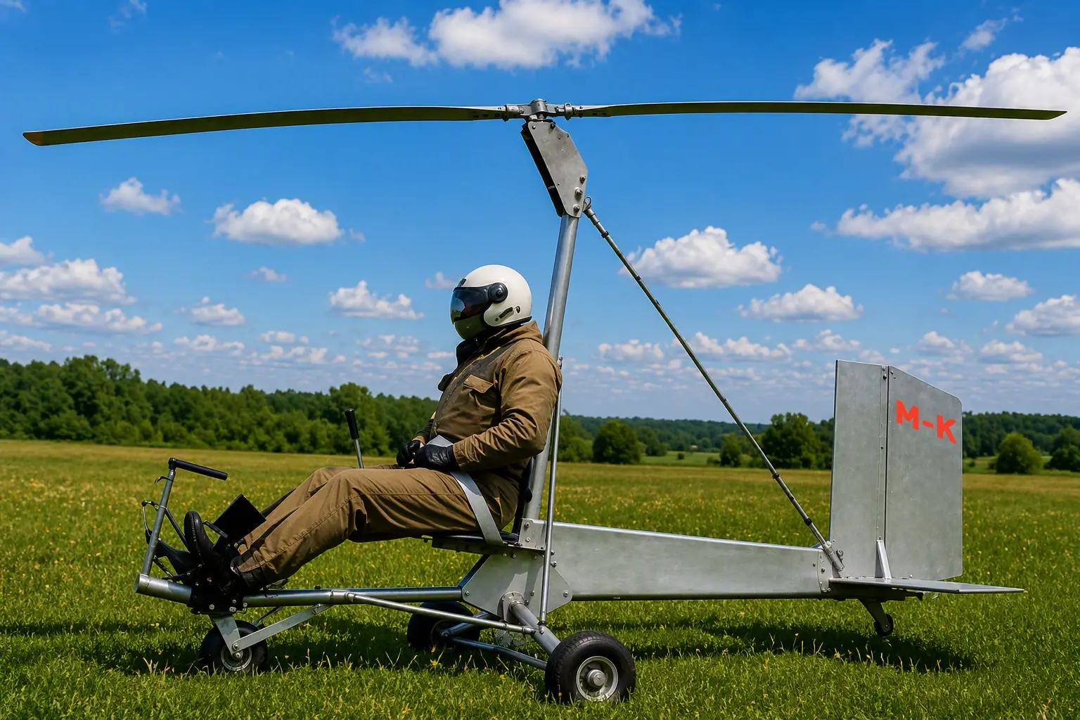
FUSELAGE CONSTRUCTION. In recent issues of our magazine, a series of articles by a group of autogyro designers was published about the features of building these rotary-wing machines, about how to build autogyros, and how to fly them when towed by a boat or an automobile.
In this issue we describe the fuselage construction and control systems of an autogyro (or gyroplane, since they are identical).
The fuselage of an autogyro, or, more correctly, the structure on which the pilot’s seat, controls, landing gear, rotor, fin, and rudder are mounted, consists of a longitudinal beam to which a cross beam and the rotor pylon are attached. All these parts are made of D16T duralumin tube 65×2 mm in diameter. The longitudinal beam is connected to the pylon by shaped gussets fastened with through bolts and spacer bushings. A cross beam (“side view”) is attached to the lower flanges of the gussets with stirrups made of 10 mm round steel. A tubular pilot’s seat frame (“front view” and “side view”) is attached to the front flanges of the same gussets. Auxiliary parts such as the rotor pylon braces, pilot’s seat, tow-lock pyramid, control stick suspension, and tail wheel are also attached with bolts and flat steel gussets.
The fin and rudder have a frame of pine strips covered on both sides with 1 mm aircraft plywood. The suspension fittings are made of 2.5 mm sheet steel.
The upper fitting for the braces, which also carries the pilot’s seat back, is a clamp made of 5 mm sheet steel.
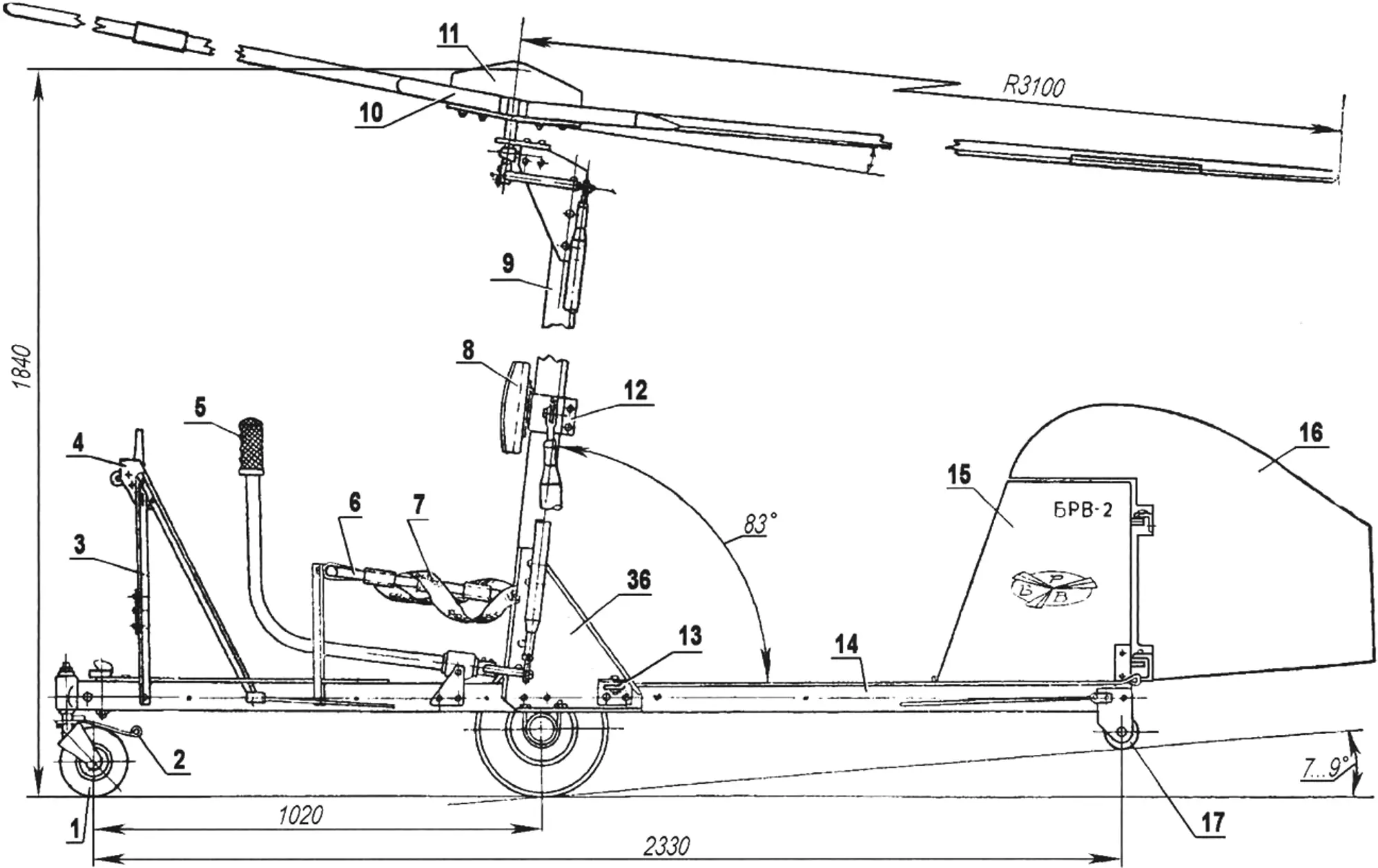
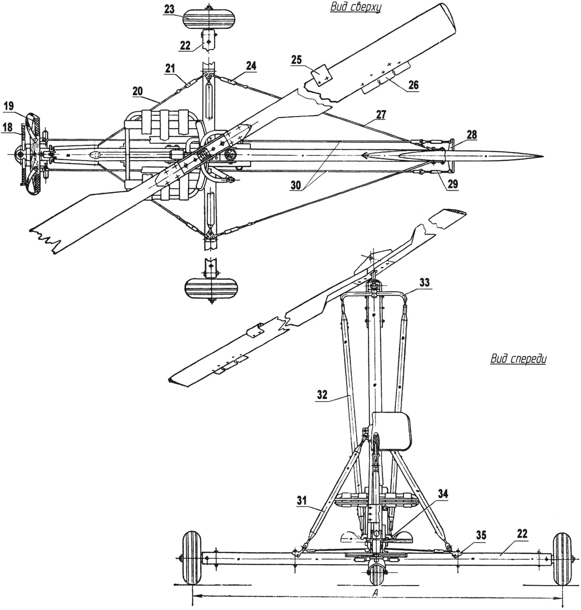
1 – steerable wheel 150×80 mm; 2 – brake plate, D160 s.2; 3 – pyramid (D160, angle); 4 – tow lock; 5 – control stick (steel 30KhGSA, Ø 35×1; 6 – pilot’s seat (steel 20, Ø 20×1.5); 7 – safety belts (set); 8 – pilot’s seat back (FAB, PS-1); 9 – pylon (D160, Ø 65×2); 10 – rotor blade (FAB and foam); 11 – rotor hub frame (D16T); 12 – upper brace attachment fitting (steel 20, sheet s5); 13 – support roller (D16T); 14 – fuselage beam (D16T, Ø 65×2); 15 – fin (FAB sheet s1, pine strip); 16 – rudder (FAB sheet s1, pine strip); 17 – tail wheel (D16T, rubber); 18 – nose wheel control pedal, D160, angle; 19 – rudder pedal (ash); 20 – front bracing wire (OVS Ø3); 21 – turnbuckle M5 (finished part); 22 – cross beam (D16T Ø 65×2); 23 – main landing gear wheel (300×125); 24 – turnbuckle M5 (finished part); 25 – anti-flutter weight (steel 20 sheet s1, lead); 26 – blade trim tab (D16T sheet s1.5); 27 – rear bracing wire (OVS Ø3); 28 – rudder horn (steel sheet s2); 29 – turnbuckle M3 (finished part); 30 – control cables (Ø 2.2); 31 – brace (D16T Ø 35×1); 32 – control rod (D16T Ø 28×2); 33 – upper fork (steel 30KhGSA Ø 20×2); 34 – lower fork (steel 30KhGSA t Ø 20×2); 35 – lower brace attachment fitting (steel 20 sheet s3); 36 – shaped gusset for pylon-to-beam attachment (steel 20 sheet s5)
The tow-lock and instrument panel pyramid is made of equal-leg D16T duralumin angle (25×3 mm). The tow lock is similar in design to those used on light training sailplanes and is made of St 20 sheet steel 3 mm thick; the hook is made of 5 mm sheet steel.
The fuselage is assembled in the following sequence: after connecting the longitudinal beam, on which all auxiliary parts are mounted, to the rotor pylon with gussets, the cross beam is installed. The wheel half-axles and lower brace attachment fittings should already be mounted on it. Then, using the braces, the pylon is adjusted strictly perpendicular to the cross beam and fixed in that position with locknuts. Correct alignment is checked by stretching a steel wire between the outermost points of the structure. After that, with the resulting cruciform frame placed on a level surface and secured immovably, the pilot’s seat, tow-lock pyramid, tail unit, and landing gear wheels are mounted. The rotor, previously assembled on the hub, is mounted last.
Steel parts must be protected against corrosion by first applying AG10 or 138 primer and then light-toned nitro enamel. Small parts (gussets, bolts) should preferably be galvanized or cadmium-plated. Tail unit parts are primed and painted by the usual process.
CONTROLS
In flight, like an airplane, an autogyro can move and be controlled about three spatial axes: vertical, longitudinal, and lateral. Deflecting the control stick causes the rotor disc plane to tilt, thereby creating the required pitching or rolling moment. Directional control, as on an airplane, is provided by the rudder mounted on the fin at the rear of the fuselage.
Stick and pedal movements on an autogyro follow established airplane flying practice, based on a person’s instinctive movements to maintain balance.
The main general requirements for the autogyro control mechanism are listed below by item for convenience during preflight checks:
1. Sufficient control rigidity.
2. Minimum control lag due to friction, free play, and deformation. It must not exceed the value determined by human reaction speed (1/7 sec.).
3. Moderate forces on the stick and pedals. When deflected from neutral, the forces should preferably increase smoothly and be directed opposite to the deflection (the so-called positive stick force gradient).
4. Absence of vibration. There must be no stick “wandering” or pedal “kicking.”
5. Durability and strength. Rotating parts — bearings, ball joints, and pins — must have the required service life.
6. Independence of longitudinal, lateral, and directional control. For example, longitudinal stick deflection must not cause roll.
7. No binding in the control runs and mechanisms when the fuselage and other autogyro parts through which the controls pass are deformed.
8. Limit stops for longitudinal stick and pedal deflections, installed directly on them.
9. A margin of control deflection angles (somewhat greater than required by calculation or test data).
10. Lubrication and protection of joints and rubbing parts in control connections from dust and moisture.
11. Convenience of inspection, assembly, and disassembly of control units.
The autogyro control mechanism (Fig. 1) consists of control stick 2, lower support 10, lower fork 8, two rods 4, upper fork 7, and upper support 12.
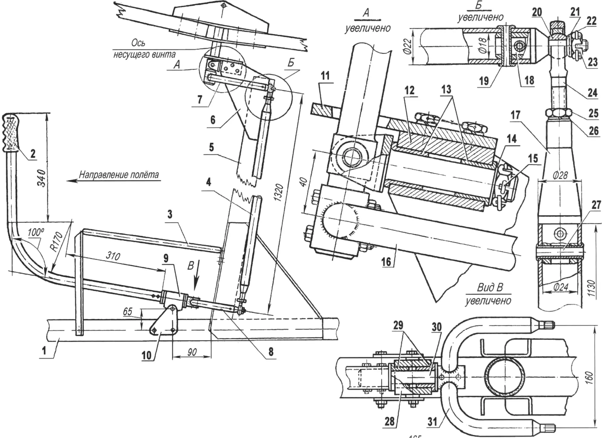
1 – longitudinal beam (fuselage); 2 – control stick; 3 – pilot’s seat; 4 – rod (left); 5 – pylon; 6 – pylon cheek; 7 – upper fork; 8 – lower fork; 9 – housing; 10 – support cheek; 11 – stop; 12 – upper support housing; 13 – bushings; 14 – washer; 15 – cotter pin Ø2 mm; 16 – upper fork; 17 – rod end; 18 – fork end; 19 – pin Ø 6×1 mm; 20 – HS-10 head; 21 – washer; 22 – cotter pin Ø 1.5 mm; 23 – nut; 24 – clevis bolt; 25 – locknut; 26 – lock washer; 27 – pin Ø8×1 mm; 28 – support housing; 29 – bushings; 30 – adapter shaft; 31 – lower fork
The stick is mounted on longitudinal fuselage beam 1 with a bolt about which it can oscillate in the longitudinal plane.
Stick movement in the lateral plane is transmitted to the fork through a shaft installed in bronze bushings in the lower support housing. On the shaft, the stick and lower fork are secured with M6 bolts; adjusting washers may be placed on the shaft on the fork side, if needed, to eliminate axial free play. Force is transmitted from the lower fork to the upper fork by two rods with clevis bolts and ball bearings at the ends. The upper fork is attached to the rotor axis, which in turn is hinged on the upper support shaft.
Thus, moving the control stick in any direction will cause the rotor axis to deflect in the same direction.
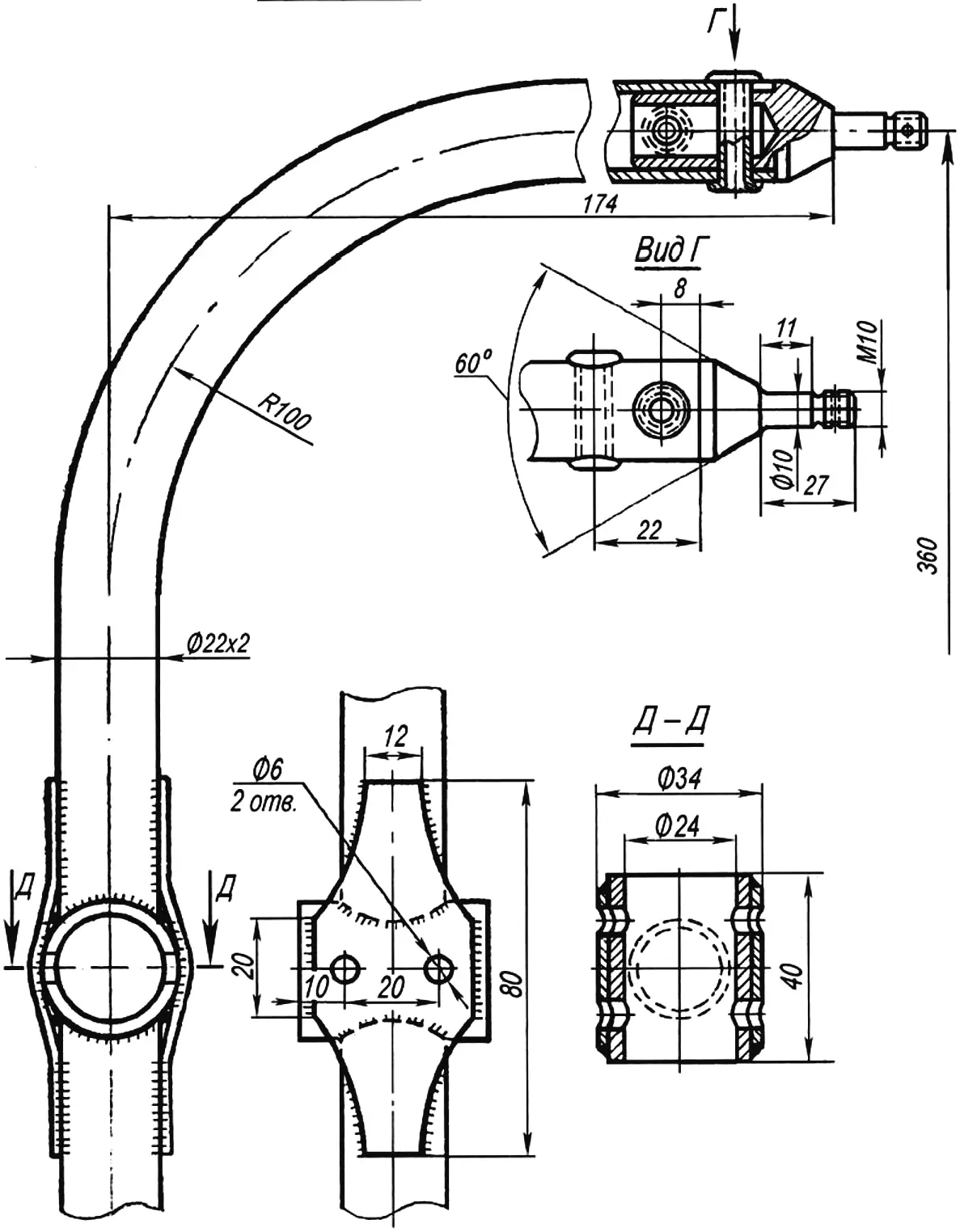
The most critical parts of the control mechanism are the forks (Figs. 2 and 3) and their ends (Fig. 4). Therefore, special attention must be paid to machining quality when making them. Welds must be even, without cavities and slag inclusions.
After bending, fork tines must have no cracks, folds, or burn-throughs. To detect cracks and incomplete fusion, it is best, if possible, to X-ray the parts or at least perform magnetic inspection after heat treatment and sand cleaning.
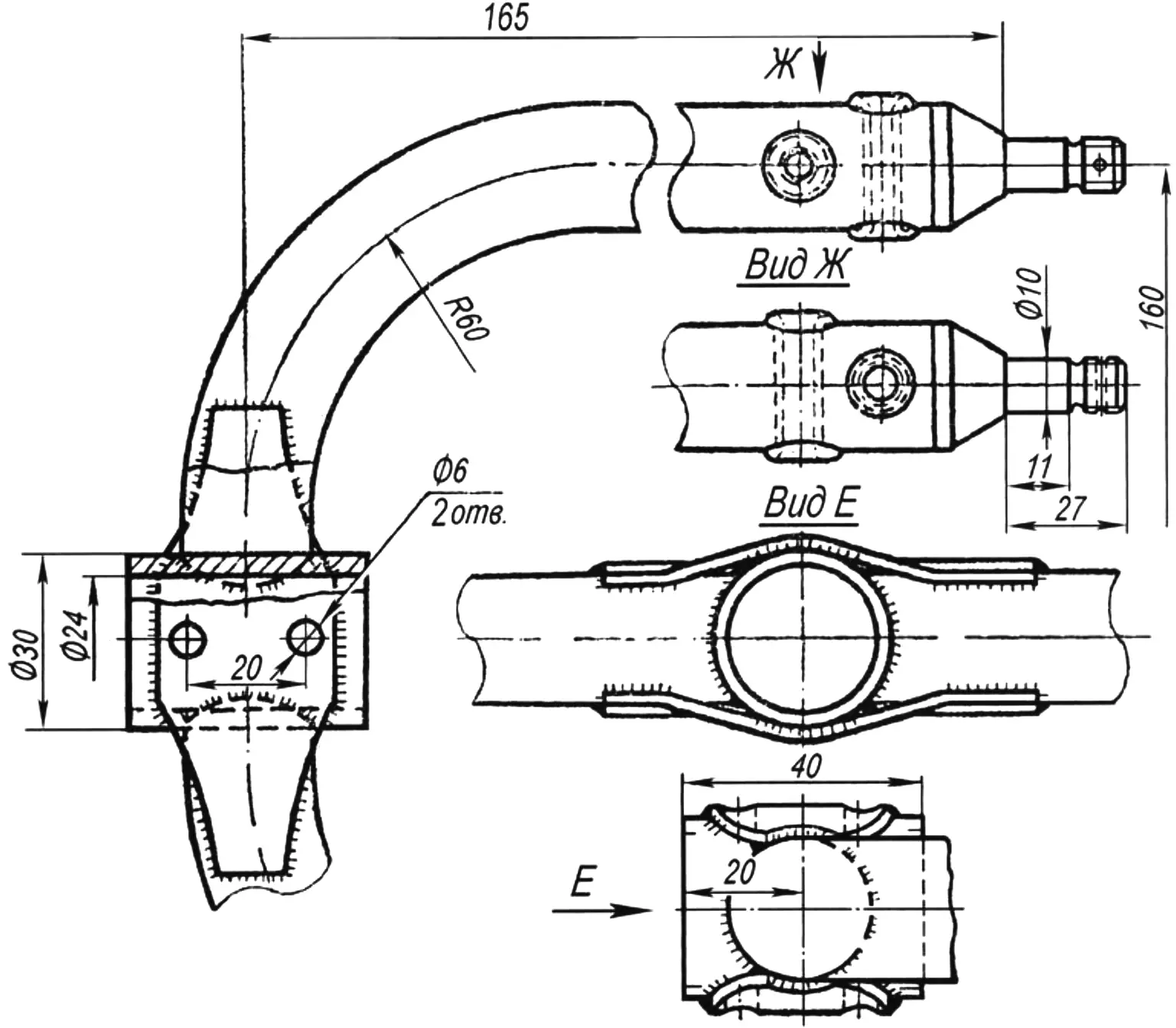
It is preferable to weld the forks in specially made jigs by arc welding. This ensures that the part geometry matches the drawing and avoids the difficult and critical operation of straightening. Immediately after welding, the forks must be heat-treated according to the drawings. After heat treatment and sandblasting, the central cups are reamed to an internal diameter of 24 and the fork ends to 18 for installing the ends.
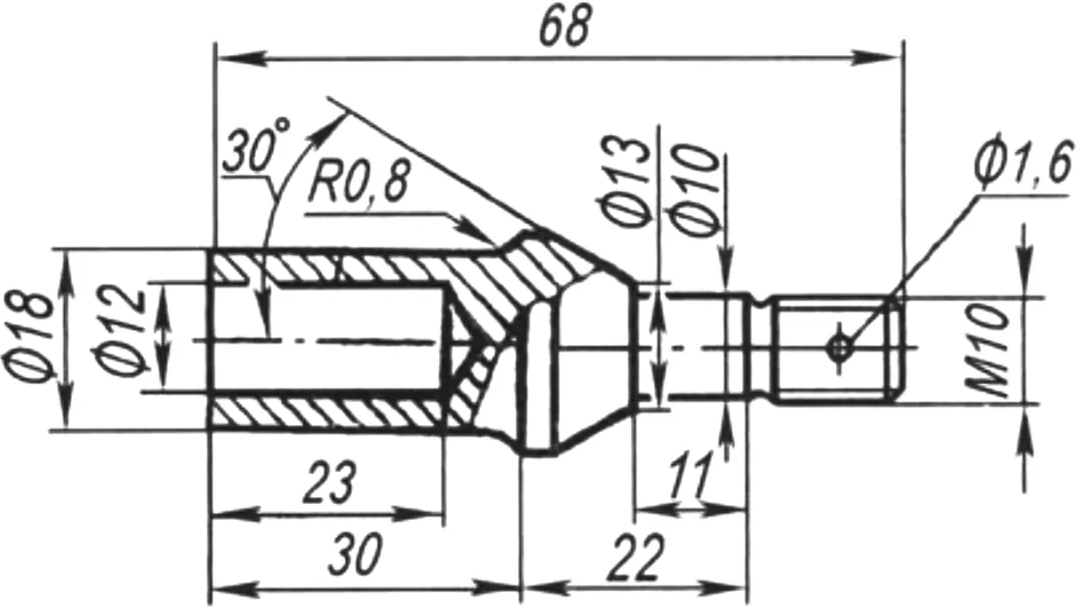
Fork ends are turned according to the drawing (Fig. 4), but 1.5-2 mm allowance is left on diameters 10P2a and 18. In this condition they are heat-treated, then the seating surfaces are turned to the required size. Special attention must be paid to the quality of the fillet radii and threaded groove shown on the drawing.
During assembly, by fitting mating parts and installing adjusting washers where required, the entire control mechanism must operate clearly without binding or free play. All nuts must be secured with cotter pins, lock washers, or staked according to the drawing (Fig. 1).
Directional control of the autogyro, as noted above, is provided by the rudder. The directional control mechanism presents neither design nor manufacturing difficulties, and its layout and operation are easy to understand from the autogyro general arrangement drawing. Fin and rudder dimensions can be taken from the same drawing, scaled up accordingly. The autogyro tail unit is easy to make by cutting parts from 10 mm plywood. In this case, bracing wires of 1.2 – 1.5 mm OVS wire must be installed on the fin. The other ends of the wires are attached through M3 turnbuckles to the cross beam at the brace attachment points.
The disadvantage of a plywood tail unit is somewhat greater weight than a unit made of a set of ribs with 1 mm plywood skin. The advantage is simplicity.
To ensure controllability about the longitudinal axis, rudder deflection must be 25° right and left from neutral. For pitch and roll controllability, autogyro rotor axis deflection must be 12° in any direction from neutral.
«Modelist-Konstruktor» No. 3’2014, Yu. RYSYUK
Recommend to read
 Lever to help
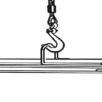
Sometimes a load lifted by a crane beam or winch (when replacing an engine in a car, for example) needs to be lowered slightly to the side from the suspension point. In this case, an...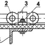 THE CATERPILLAR ON THE CHAIN
Motonarty and all-terrain vehicles on tracks are very popular in areas with snowy winters and impassable for other land transport by road. Many Amateur designers to undertake independent...
