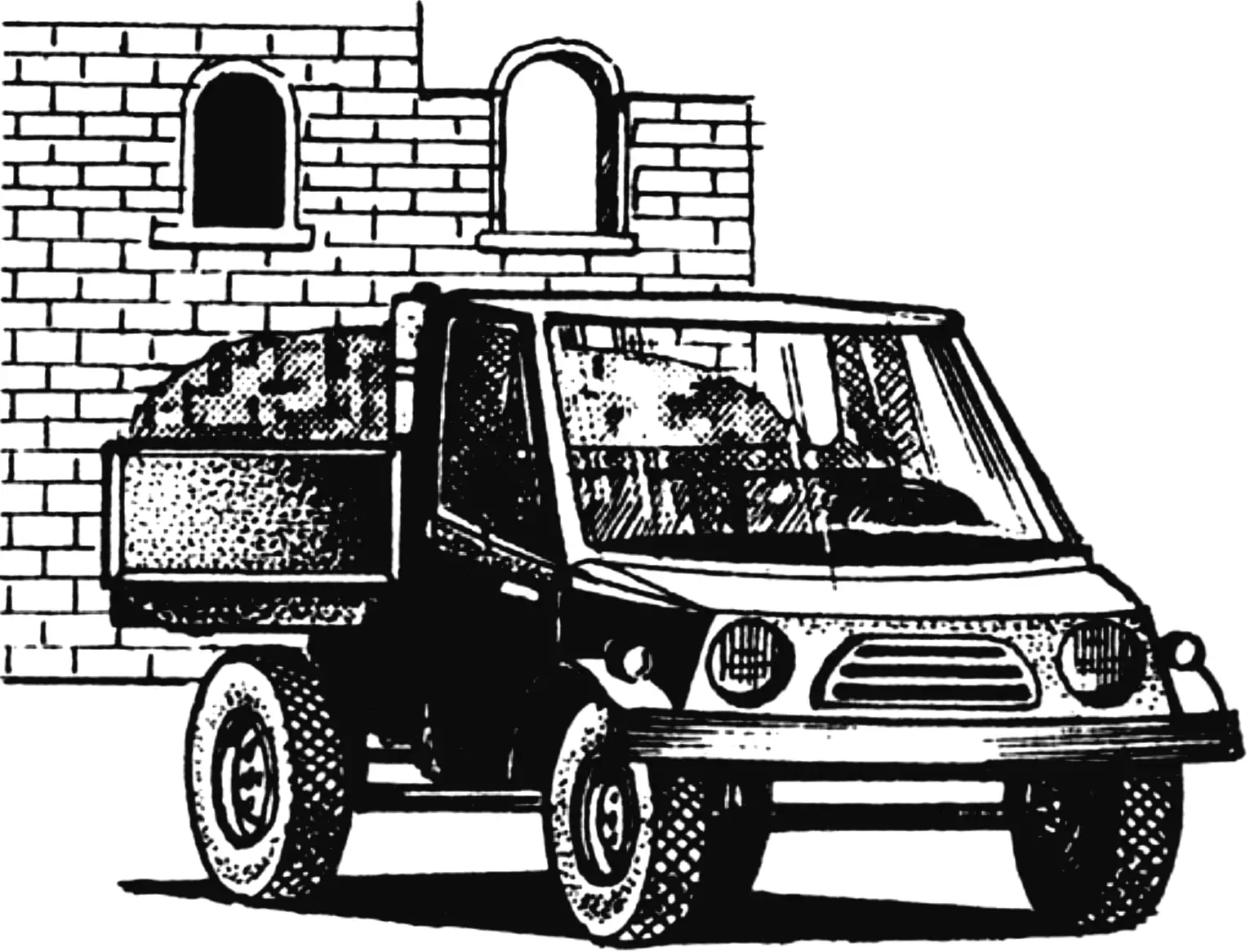
All work on a homestead or summer cottage plot is a combination of construction, transport, and purely agricultural tasks. And if, to make the latter easier, you can buy various small-mechanization tools — from a motor cultivator to a mini-tractor — then for all other work, only a trailer for a passenger car, a cart for a walk-behind tractor, or the “Muravey” motor scooter really fits.
A passenger car with a cargo trailer is good for an asphalt highway, but transporting peat or manure on it over dirt roads, turning around in a small area, or — God forbid — driving in reverse is the kind of job only a professional driver can handle.
A walk-behind tractor with a cart is a suitable freight vehicle, but its “pedestrian” speed and low off-road capability turn any cargo transport into a long and exhausting job.
The cargo motor scooter “Muravey” is also good, but its two drawbacks sometimes nullify all its advantages. The main one is the lack of a fourth wheel. The need to lay a third track line significantly reduces the off-road capability of this motor truck, does not allow passing between the wheels over ruts and stones, and does not let it move both over the ridges and into the depressions of the track. And the second drawback of “Muravey” is the absence of a cabin, which turns rides in cold weather or in bad conditions into pure suffering.
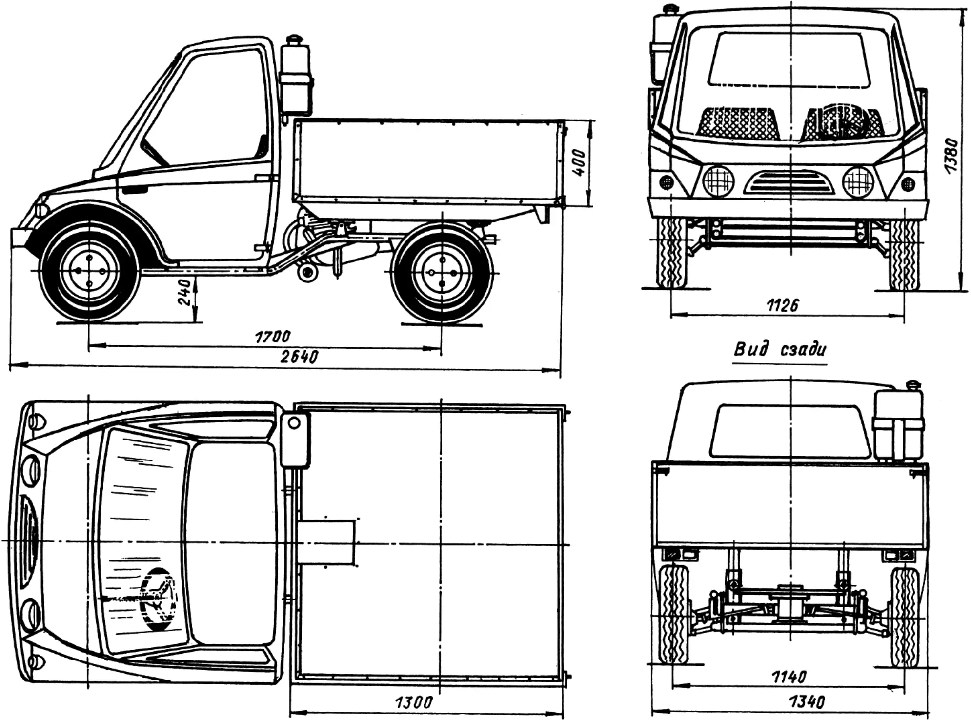
The desire to have a vehicle without the above shortcomings led to the appearance of this two-seat, comfortable motor truck with a 0.7 m3 body, named “Kompakt-200”.
The vehicle was designed using the engine from the cargo motor scooter TG-200M, as well as two front axles, the final drive, and steering control from the S3D motor wheelbarrow.
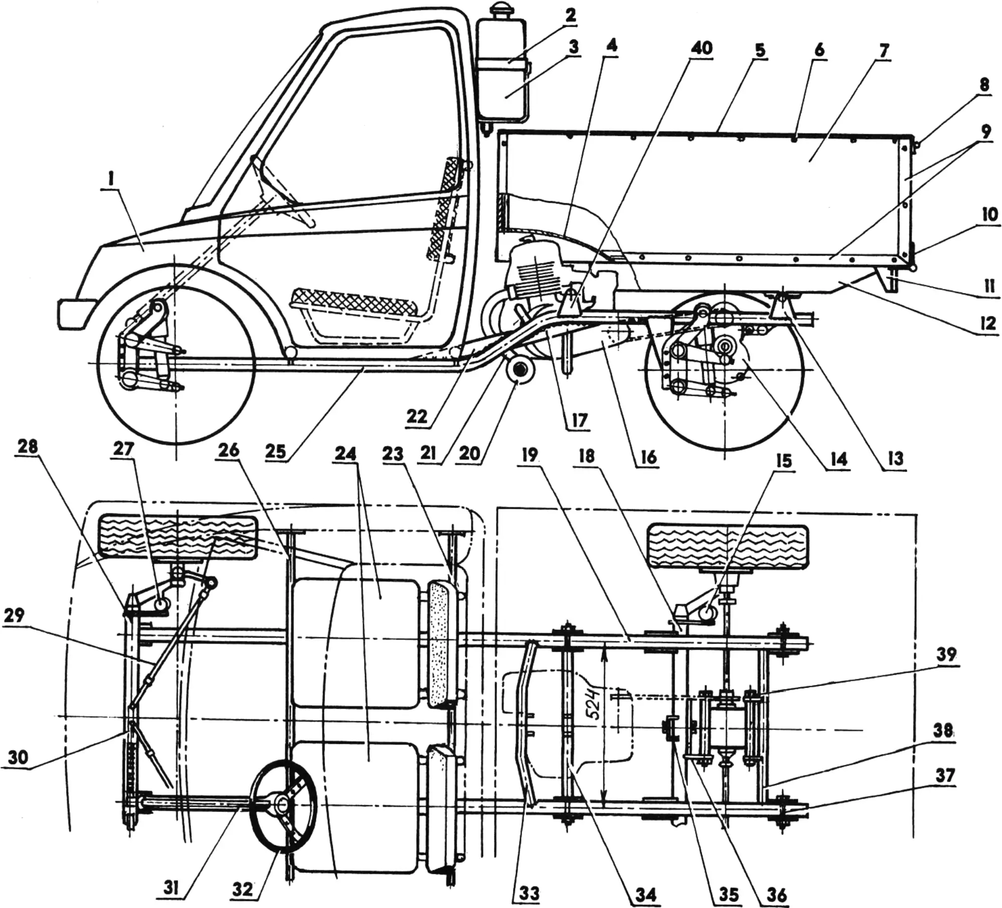
1 — cabin; 2 — clamp for fuel tank mounting (steel, strip 50×2); 3 — fuel tank (jerrycan, capacity 10 l); 4 — niche in the body for the engine cylinder (steel, sheet s2); 5 — body side trim (duralumin, angle 30x30x3); 6 — trim mounting (M5 bolt with nut); 7 — side panel (plywood s12); 8 — lock for the rear folding side; 9 — body connecting elements (duralumin, angle 30x30x3); 10 — hinge of the folding side; 11 — rear light unit; 12 — body base (pine, block 90×40); 13,40 — body mounting units; 14 — final drive (from the S3D motor wheelbarrow); 15,27 — spring-hydraulic shock absorbers (type “Voshod”); 16 — engine TG-200M; 17,22 — reinforcing gussets of the frame side members (steel, sheet s3); 18 — rear axle (front axle from the S3D motor wheelbarrow); 19,25 — frame side members (steel tube 40×3); 20 — muffler; 21 — exhaust outlet pipe; 23,26 — cross members for mounting seats and cabin (steel tube 20×2.5); 24 — driver and passenger seats; 28 — front axle (from the S3D motor wheelbarrow); 29 — steering rod; 30 — rack-and-pinion steering mechanism (type S3D); 31 — steering column (type S3D); 32 — steering wheel; 33,34 — engine mounting cross members (steel tube 30×3); 35 — mounting shoe for the final drive bracket (steel, channel 60x40x3); 36 — final drive bracket (steel, sheet s3); 37 — body mounting (M8 bolt with nut); 38 — cross member for final drive mounting (steel tube 30×3); 39 — final drive mounting (M10 bolt with nut and spring washer)
The rear axle of this truck is a modified front axle from the S3D motor wheelbarrow — at the wheel hubs, the tubes were cut off and brackets with holes for mounting pins to the axle levers were welded in. In addition, the standard hydraulic shock absorbers were replaced with motorcycle spring-hydraulic ones, which increased the vehicle’s payload capacity. The front axle, meanwhile, is mounted to the frame with practically no modifications.
The motor truck has a welded tubular frame, a plywood body reinforced with duralumin angle bars, and a cabin with a steel tubular frame and skin made from foam, orgalite, fiberglass cloth, and epoxy binder.
The frame’s power basis consists of two steel-tube side members of 40 mm diameter with a 3 mm wall thickness. On the front portion of each side member, mounting feet for the front axle are welded, and for mounting the rear axle to the frame, brackets cut from 3 mm thick sheet steel are welded.
The axles are connected to the mounting units on the side members in the same way as on the motor wheelbarrow — with bolts and nuts, and with split spring washers. After checking the frame for symmetry, for absence of misalignment, and for compliance of its dimensions with the drawings, the body mounting units and tubular cross members are welded. Two of them — made from a 20 mm diameter tube — are intended for mounting the seats and cabin, two, bent from a 30 mm diameter tube — for the engine motor frame, and one, at the rear part of the frame — a support of the final drive (reverse gearbox/reducer). As the drawings show, the reverse gearbox/reducer is installed vertically, with the sprocket (by the way, from a cargo motor scooter) pointing up, while the reverse engagement lever is located in front of the machine’s direction of travel.
The engine is mounted on the frame by its lower and front units — that is quite sufficient. The exhaust outlet pipe is standard, from the TG-200M; the muffler is homemade and is a hollow cylinder inside of which there is a fine-mesh steel net rolled tightly into a small spiral roll.
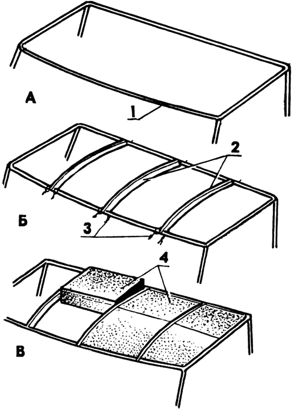
1 — cabin frame (steel, tube 16×2); 2 — bulkheads (plywood s6); 3 — temporary bulkhead fastening with wire twists; 4 — filling (construction foam)
The truck body is assembled from 12 mm thick plywood panels. The blanks prepared for assembly are soaked twice with hot drying oil and covered in two layers with oil paint. The body is assembled using duralumin angle bars 30x30x3 mm and M5 bolts with a countersunk head and nuts. Moreover, at the junctions of the panels the angle bars are placed both outside the body and inside — this made it possible to obtain a fairly rigid structure. The side trim is also made from duralumin angle bars. The body base consists of two pine bars with a cross-section of 90×40 mm, fixed to the floor from below with M6 bolts and nuts. Before installing, the base bars are soaked twice in drying oil and coated with oil paint. In the front part of the body there is a niche for the engine cylinder — it is welded from a 2 mm thick steel sheet and fixed to the body with M5 bolts and nuts.
The motor truck cabin is assembled using a technology that is very advantageous for amateur construction. First, a light cabin frame and door frames are welded from thin steel tubes. The frames of the front and rear glass are also welded onto the structure. By the way, for this motor truck, as the front window, it was very successfully used the glass from the rear door of the Moskvich-2141, and a part of the same door was used to form the cabin’s front panel.
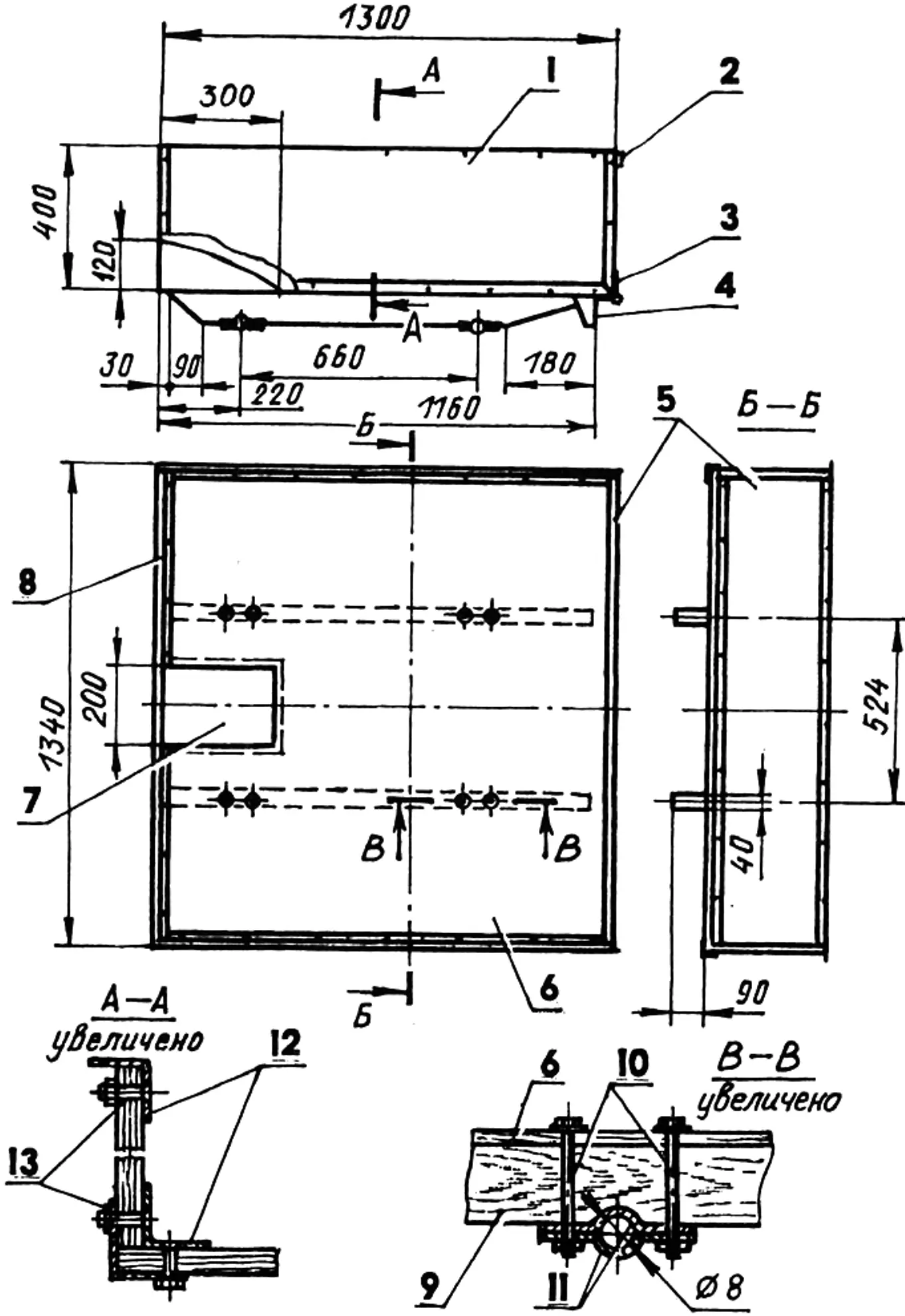
1 — side panel (plywood, s12); 2 — locking latch for the rear folding side; 3 — hinge of the folding side; 4 — bracket of the rear lighting unit (steel, sheet s2); 5 — folding side panel (plywood s12); 6 — body floor (plywood s12); 7 — sheathing of the niche (steel, sheet s2); 8 — side trim (duralumin, angle 30x30x3); 9 — body base (pine, block 90×40); 10 — mounting bolts M8 with nuts and washers; 11 — half-clamps (steel, strip 40×3); 12 — body connecting elements (duralumin, angle 30x30x3); 13 — bolts M5 with nuts
Next, bulkheads were cut out of plywood and fixed with soft wire to the frame tubes; after that, the space between the bulkheads was filled with blocks of construction foam. At the same time, the forming of the cabin itself and the doors was carried out in one piece (monolithically). The cabin surfaces were leveled using a long, finely sharpened knife, a homemade plane whose iron is set at a 45-degree angle to its axis, and coarse-grit sandpaper.
After processing the outer surfaces, the thickness of the foam filling was brought to 20 mm. To control the shell thickness, “markers” were used — ordinary matches cut to 20 mm and painted with a felt-tip pen. (“Markers” are inserted from the outside into the foam flush with the cabin surface, and when processing the inner surfaces, the material is removed sequentially until the cutter catches onto the next marker.)
The cabin surfaces prepared this way were covered with fiberglass cloth — one layer on the inside and three layers on the outside. After the binder polymerized, doors were cut out using a fine-tooth hacksaw; then the door openings and door ends were processed. The interior is lined with faux leather.
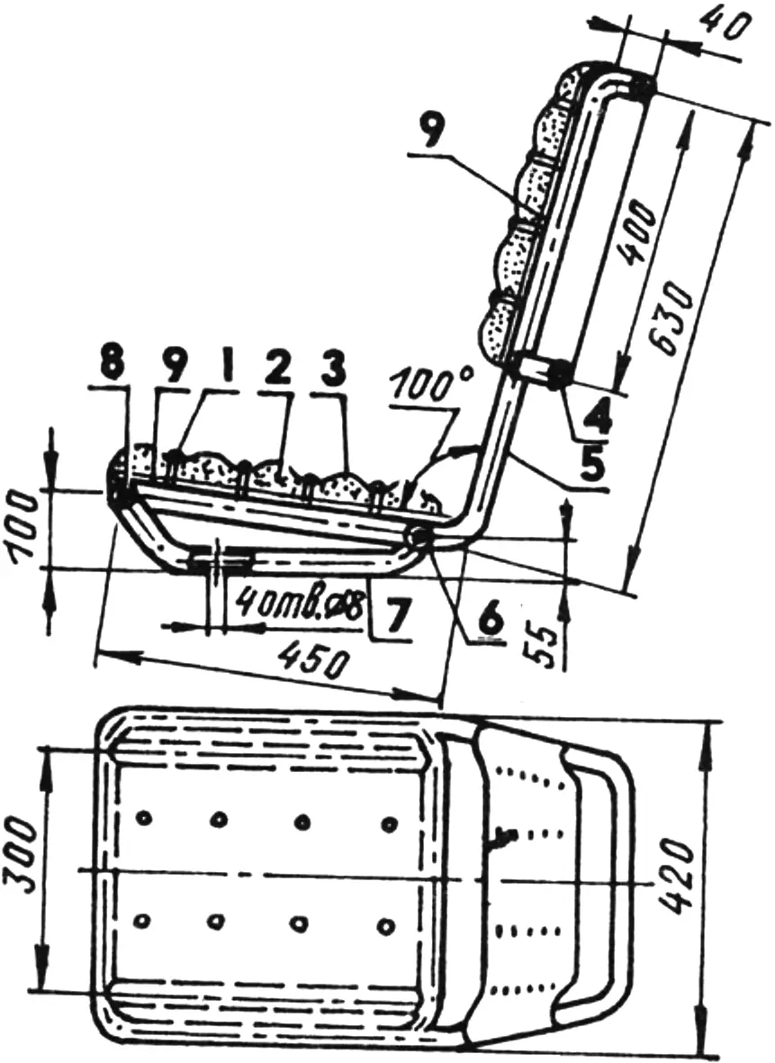
1 — decorative button; 2 — cushion (foam rubber); 3 — upholstery (faux leather); 4 — backrest cross member; 5 — frame base; 6,8 — lower seat cross members; 7 — seat support; 9 — resilient elements of the seat and backrest (rubber rings)
The driver and passenger seats are homemade: they are tubular frames covered with rubber rings cut from a truck wheel inner tube, foam rubber, and faux leather.
Steering of the motor truck is of the automotive type. The braking system is hydraulic, from the S3D motor wheelbarrow. Throttle and clutch are controlled by cables. The pedal block (throttle-brake-clutch) is mounted on hinge units welded to the frame side members. The gearshift handle is located between the seats under the driver’s right hand; the gearbox drive is via a rigid rod and an intermediate lever. On the right side there is also a handle for engaging the reverse gear (reverse).
The vehicle’s electrical diagram is the same as on the “Muravey”. From the same motor scooter come the headlights, turn indicators, speedometer, ignition switch, and warning lamps.
Technical specifications of the light motor truck “Kompakt-200”
Engine, type … TG-200M
Displacement, cm3 … 200
Power, hp … 4
Final drive, type … S3D
Wheelbase, mm … 1700
Track (front), mm … 1126
Track (rear), mm … 1140
Payload, kg … 400
Max speed, km/h … 60
Fuel tank capacity, l … 10
“Modelist-Constructor” No. 9’2001, I. KHOROSHEV, engineer
Recommend to read
 START INTO THE WIND
Mount klementieva in Koktebel — a place special and wonderful in their own way. Fans of soaring rightly consider it the cradle of Soviet gliding, nascent in our country in the distant... LAMP FAN
Fans of tinkering a small chandelier for bedroom or small room. It is simple in design, and vultures even schoolchildren, who owns a jigsaw and a file. For its production you will need...
