 The agricultural theme, perhaps the most characteristic in the work of young radio Amateurs from syut Novosibirsk region. 14 new products — electronic devices for agriculture — provided they are meeting in Magnitogorsk. The originality of technical solutions, the relevance of development of children marked by the true: the majority of devices are awarded with diplomas and valuable prizes.
Today our story — about two works of the Novosibirsk school students: Andrei Nikonov and Sergey Tarasov.
This device (Fig. 1) quickly determine percentage of moisture in different substances. The measurement produced by comparing the weight of a test sample before and after drying it with high frequency currents.
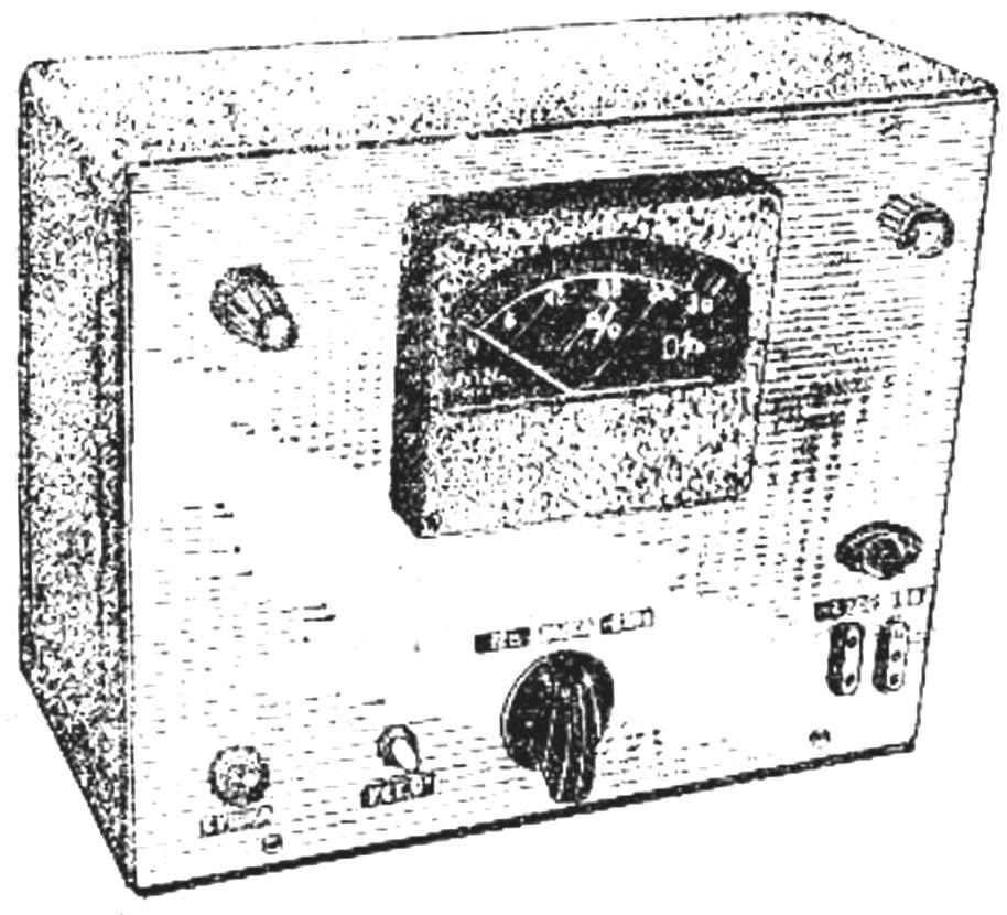
Fig. 1. The appearance of the device to determine the moisture of substances.
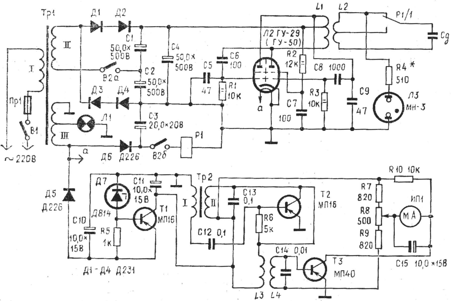
Fig. 2. Schematic diagram of the humidity meter R1 — relay РЭС6 (RIF. 452. 144).
To determine the moisture content of the substance, it is not necessary to pre-weigh. Samples are placed in a special camera sensor, and the arrow indicator electronic scales, embedded in a device installed in the rightmost position using the adjusting screw.
With the removal of the moisture weight of the substance is reduced gradually. These changes fixes the indicator scale which is calibrated in percent humidity (0 to 30%).
The power universal AC voltage of 220 V or from a car battery voltage of 12 V. In the first case, the time of complete drying of the sample is about 6 min, and the second 10-15 min 10-20 times faster than in laboratory measurements.
Schematic of the device (Fig. 2) consists of three blocks: a generator of high frequency, electronic scales and food.
RF generator, assembled on the circuit of the electronic treatacne on the lamp GU-29, works at a frequency of 1.5 MHz. Its capacity — about 40 watts — enough to stuff with a moisture content of 20-30% dried to two-percent humidity for 5-6 min.
For weighing of sample applied to scales consisting of a generator, measuring coils L3 and L4, rectifier and gauge ИП1. Scales arranged as follows (Fig. 3). To the side wall of the enclosure using the screws attached to the end plate 150X7 mm, made of spring from an old alarm clock. The plate is isolated with a layer of sticky tape. The other end of the plate, at a distance of 50 mm from the edge of the wound coil L3 that contains 150 turns of wire of PEL 0,1. The wires are glued along the plate with glue BF-2. Under the coil L3 coil L4 is placed, which is used universal head from a tape recorder. When the plate approaches the coil L4, the induced current in it increases.
To the free end of the suspended plate sensor with the target substance.
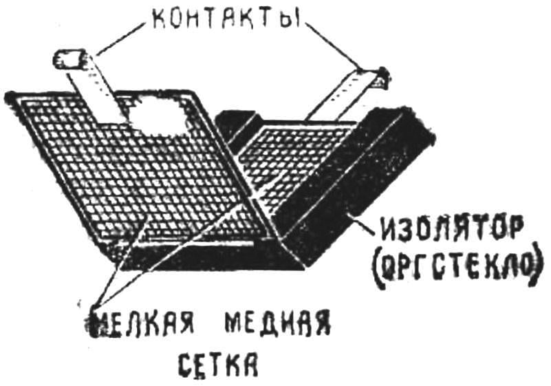
The sensor (Fig. 4) is a capacitor electrode which is made of a fine copper mesh, framed wire Ø 1 mm. Between the plates of the sensor is placed a frame made of Plexiglas. One plate should freely open, so she bonded with the insulator hinge, made of steel wire Ø 0,3 mm. Not upravlyaut in plexiglass. The other plate is fastened tightly to the frame. Both plates are attached to the contacts made in the form of hooks. Exactly the same contacts mounted on insulators on the spring balance. One contact soldered to the plate, and the other, insulated from it, a thin stranded wire is connected to a generator of high frequency. After downloading the sensor is hung to the scales on the hooks. The NCH weights generator operates at a frequency of 1000 Hz. Adjusting the weights of the tape head should be adjusted so that, at the convergence of the coils L3 and L4 of the measuring device ИП1 increased testimony, Then drying the sample plate will move away from the head of the tape recorder and the readings will decrease proportionally remote moisture.
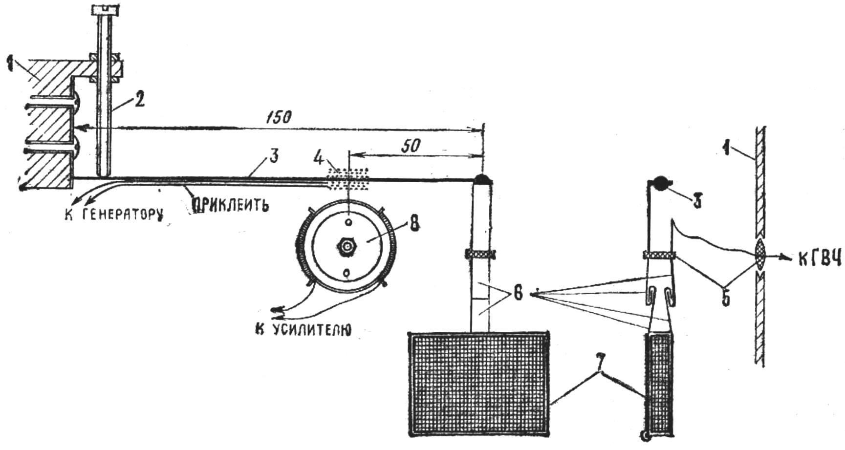
Fig. 3. Design of electronic scales:
1 — housing unit; 2 — adjusting screw; 3 — a spring plate; 4 — coil L3; 5 —insulators; 6 — contact plate; 7 — gauge; 8 — tape head (L4).
In the curing chamber is made up of about 8-10 g of the test substance. However, the weight of the sample is not critical and, as shown, the error in different the weight is not more than 10%. If the humidity of the sample is significant, any failure of the high-frequency generation. In this case, a sensor with a relay R1 is connected to the drain coil L2.
The rectifier is assembled according to the scheme of the voltage. The power transformer TR1 is used to cook from TVs CNT 47/59.
As applied to TP2 of the transformer matching transformer from handheld radios. The primary coil contains 1,500 turns, secondary winding 400 turns of wire PEL of 0.12.
The coil of an oscillatory contour of L1 is wound on a ceramic frame Ø 30 mm, length 60 mm and contains 160 turns of wire PEL of 0.6 with the withdrawal of the 80th round. 12 contains 80 turns of the same wire with a tap 40 turns. The coil is placed inside the frame. Voltage Converter is made according to the scheme published in the magazine “Radio”, No. 9, 1972. Output voltage — 350 V, the current is 0.08 A.
To exclude the interference created by the generator, the device with the power supply housed in a metal case.
Recommend to read
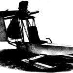 SLEIGH WITH AEROFOAMY
The manufacture of snowmobiles, which will go below it preceded by the construction of more than a dozen of the other: single and double; single, double and trehlistnyj schemes.... THE FLIGHT ACROSS THE ENGLISH CHANNEL WITHOUT A MOTOR
To fly like a bird, the strength of your muscles, very tempting; dreamed about it many of our ancestors. Already in the XV century, when on flights in the modern sense could not even...
