
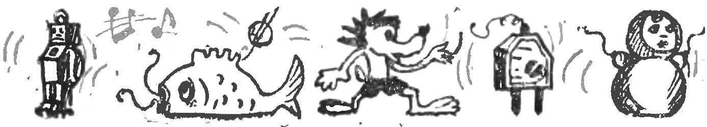
 Take a look at the placed on the fourth page of the cover. It would seem that the similarities between these fun figures and radio? However, a question may ask the inexperienced reader, but for the guys from the Moscow Palace of pioneers there are no secrets: inside each colorful souvenir — detector receiver. For example, this tiny doll made by Vladimir Trusov, takes the radio station “Mayak”, operating on the wave of 547 m, and “Lunokhod” Yuri Kozyrev— long-wave radio station on the wave of 1734 m.
All radios made by novice radio Amateurs. Despite the fact that the scheme (Fig. 1) simple, the guys worked thoroughly and seriously. And here is the result — excellent gifts for your parents, friends or acquaintances.
Anyone who wants to produce a souvenir, can safely get to work. First of all, the guide is necessary to know the wavelength of the nearest powerful radio station in Central or local broadcast. For example, 344 m.
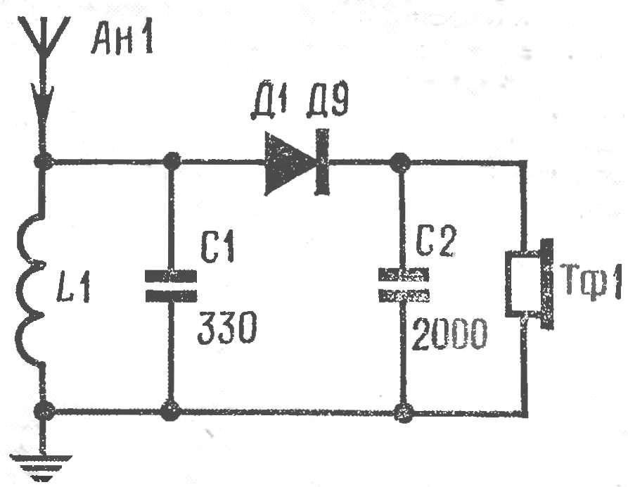
Fig. 1. Schematic diagram of the receiver.
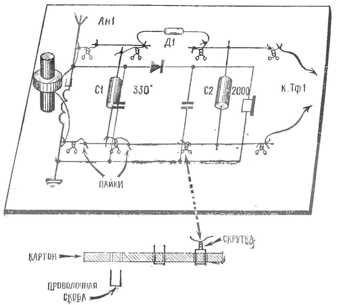
Fig. 2. Working model of the receiver.
Now calculate the inductor L1. For this you need to know the capacitance of the capacitor C1 of the oscillating circuit. It depends on wavelength: the longer the wave, the larger the capacity C1. So, for the wave is 344 m it is selected in the range 300— 390 pF. In this example, 330 pF.
The inductance of the coil is determined by the formula
L = 0,282 λ2/C µh,
where L is the inductance of the coil, µh and λ is the wavelength, m; C is the capacitance of the capacitor circuit, pF.
Substituting the selected values of the wavelength and the capacitance of the capacitor, we get: L = 0,282·3442/330 = 101 µh.
Coil form manufacture from a strip of paper, wound with several layers on a circular disc Ø 0,2—1 cm In each layer of paper smeared with glue BF-2. After it dries, the frame is cut to the desired length
Knowing the diameter of the frame and the inductance of the coil, determined by the number of turns:
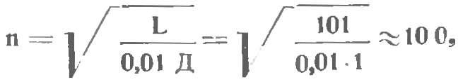
where L is the inductance of the coil, µh; D — diameter of the cage, cm; n — number of turns.
Ferrite core the number of turns for 10-20% less than estimated.
The coil L1 spool bulk wire of PEL 0,15— 0,2 and assemble a working model of the receiver (Fig. 2) on a piece of cardboard with a size of 60X90 mm. To the circuit connect the antenna, ground and headphones. If the sound in the headphones quietly or with noise from a neighbouring station, then, gradually unrolling the coils, or by introducing into the coil the ferrite core, to achieve good reception.
It now remains to determine the size of the circuit Board in accordance with the dimensions of the body and transfer all the details of the receiver. Previously on the sheet of paper in the cage or on graph paper will watertite wiring diagram in full size, achieving the best variant of arrangement of parts. (Aim to the wires connecting parts as short as possible.) The fee fabricated from Micarta, textolite, plywood or presspahn.
In conclusion, check again the quality of the receiver and, if there is no errors, install the circuit Board into the housing, making the conclusions of the antenna, ground and phones. Please note: all conclusions are integrated with the appearance of the receivers of the gifts.
A. PUTYATIN
Recommend to read
 SEAM FOR EVERY TASTE
The appearance of the brick buildings depends on the quality of bricks and the decoration of seams. Of course, the professional masons for finishing seams using a special rasshivkoj not...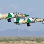 JL-8/K-8 Karakorum (China/Pakistan)
Combat training aircraft K-8 Karakorum was created in 1986 jointly by the Chinese company HAIG and Pakistani RACES. The first prototypes were assembled in 1989, the First flight took...
