 I designed a digital timer, which wrist watch, MONTANA, has a great standby time (up to 24 hours), good precision (the error is only a few seconds per day), simplicity, performance and small power consumption in the standby mode. The latter allows you to use the timer as a cost effective and pretty original clock. However, the load in this case is used with a tape cassette that is included in the reproduction, or radio receiver, tuned to the station.
From the basic hours in the timer remain the LCD display and microplate, capable of either ALTM feeding the audio signal with an amplitude of 0.2 V. Prior to installation in a makeshift structure they are finalized.
All the refinement comes down to feasible hours even the novice homebrew operations, which are shown in the figure. Requires, firstly, open the lid and remove microplate from the housing. Replace power supply new, at the same time to clear the closing plate. Second, to the pads MODE, ALTM and DATE on the flange disk microplate solder fine strands of telephone wire in a multi-colored, so you do not confuse isolation. And finally, third, the coil spring contact in the plane of microplate apply a drop of solder with the subsequent podpisaniem another wire.
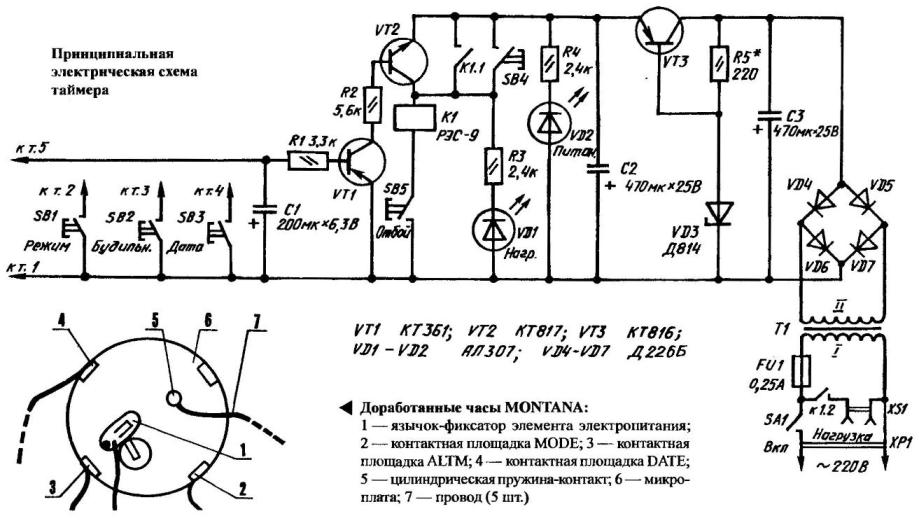
Homemade timer is nothing more than a DC amplifier, the load which is relay K1. Remove from the output 5 of the modified microplate signal is supplied to two-stage DC amplifier, assembled on semiconductor triodes VT1 and VT2. In the end, the relay K1, located in the collector circuit of the second transistor, turning one pair of contacts for locking, and feeding a second power to the load-alarm: VCR set to play favorite tunes, a receiver tuned to the “smooth” radio station, etc. a Retreat is only possible momentarily opening contacts SB5 or disconnecting the timer from the switch SA1.
The parametrical stabilizer assembled on the VT3 transistor with heat sink (metal plate 20x16x2 mm) and the Zener diode VD3, the timer ensures stable voltage supply. The required ICT can be set by selecting the value of resistor R5. Capacitors C2 and C3 constitute a filter, the voltage which is supplied from the rectifier of the diode bridge VD4—VD7. The transformer T1, which is suitable for “vychodnich” from an old tube radio— buck. If desired, it can be done yourself, using magnetic Ш14х12. The primary winding has turns 5160 ПЭВ1-0,1. Secondary— 340 turns ПЭВ1-0.25.
VD1 led indicates load switching and VD2 — on power-up.
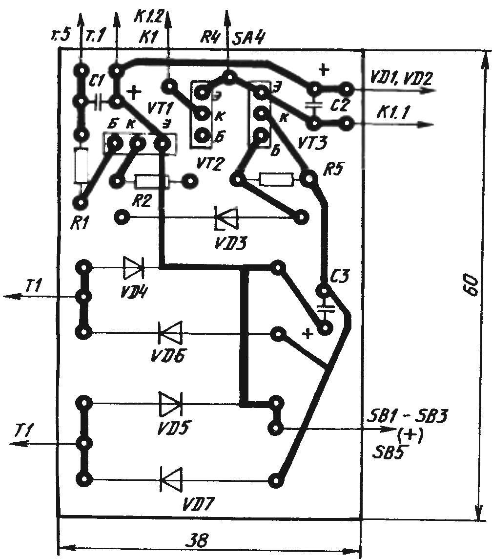
Topology of the printed circuit Board
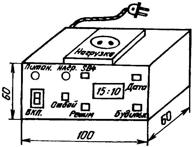
The body of the timer
The main installation of the device on a printed circuit Board made of foil Micarta or textolite dimensions 60x38x1,5 mm, which easily fits in a small plastic case. Other components and parts are attached directly to the walls. For liquid-crystal display in the casing slotted window, enclosed in a celluloid film or plexiglass.
Properly collected scheme does not require any special adjustment operations. With good detail and well-executed the installation starts to work immediately turn on the timer and setting the required values on the LCD clock display press MODE to ALARM. and the DATE shown on the front wall of the housing. For removal of doubt, we recommend you to check the voltage on C2 to ensure that this important parameter is not beyond working 9-12 V.
Recommend to read
 ON PRIMAKO — PHOTOS
When printing photos on matte paper to dry the prints in a variety of ways. Here is one of them. In the wooden rail with a cross section of 20x10 mm (length is determined by the place)...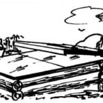 GREENHOUSE BIOFUEL
The greenhouse is hardly surprising. As in the days of V. dal, compiler of dictionary of the living great Russian, it's all familiar "hothouse without the furnace; dug-in srubar, a box...
