
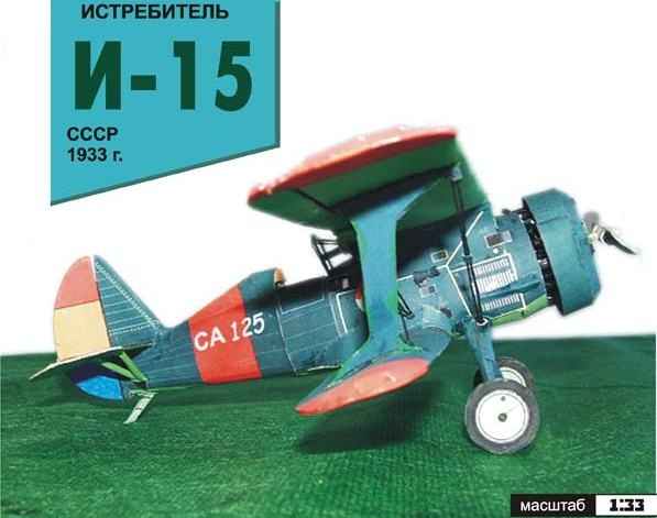
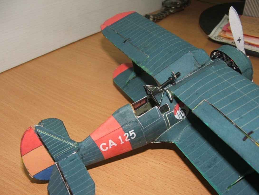
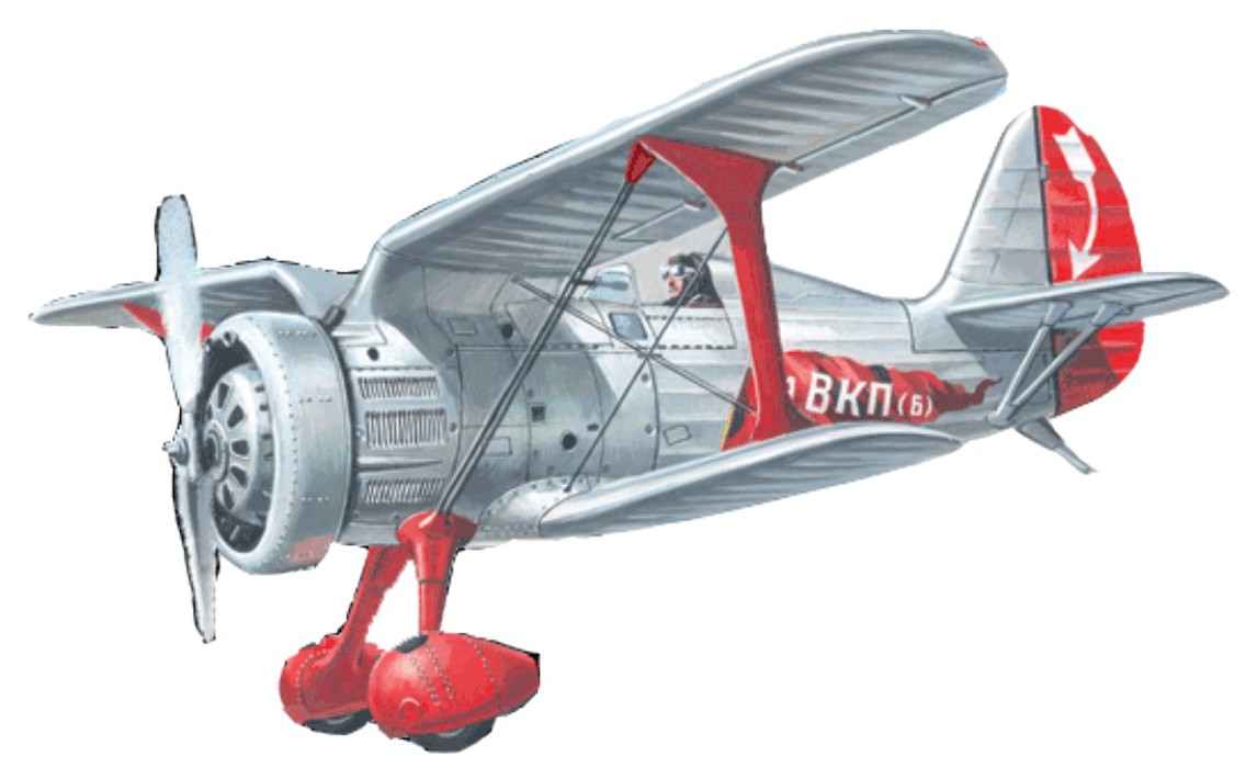
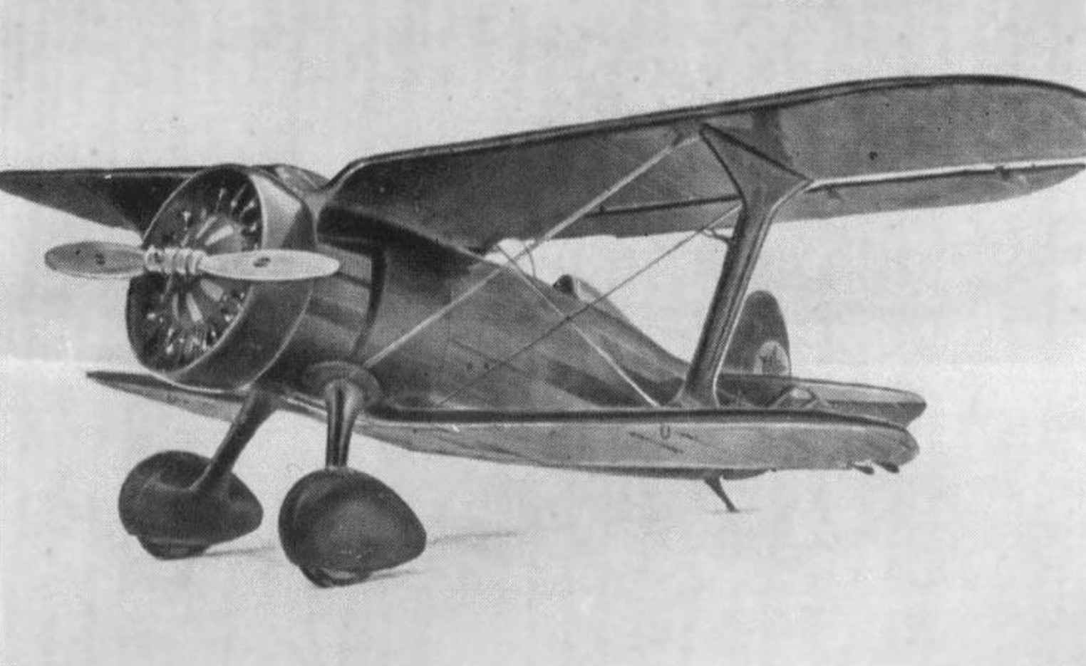
THE FIGHTER-15. Scale model 1:33.
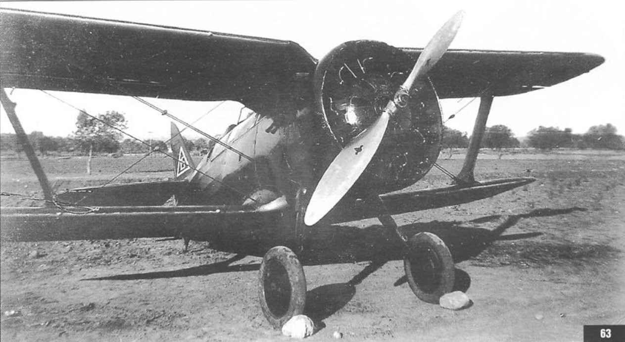
I-15 is one of the best in world practice of aircraft construction of samples of a fighter-biplane – has been developed in 1933 in Polikarpov design Bureau. The scheme and design of the I-15 was a further development of fighter I-5, but had better aerodynamics and a much more powerful motor air-cooled M-25 (license reproduction of the American Wright Cyclone f-3). A characteristic feature of the I-15 was the peculiar form of the upper wing having the circuit “Chayka”, thereby reducing aerodynamic drag and gave the best view forward and up.
 Flight tests of the I-15 began in December 1933. Fighter all indicators surpassed I-5. In 1934 I-15 was launched in a series. Steady, manageable, with high flight performance, exceptional manoeuvrability and excellent take-off and landing characteristics, this fighter used the deserved love of the pilots.
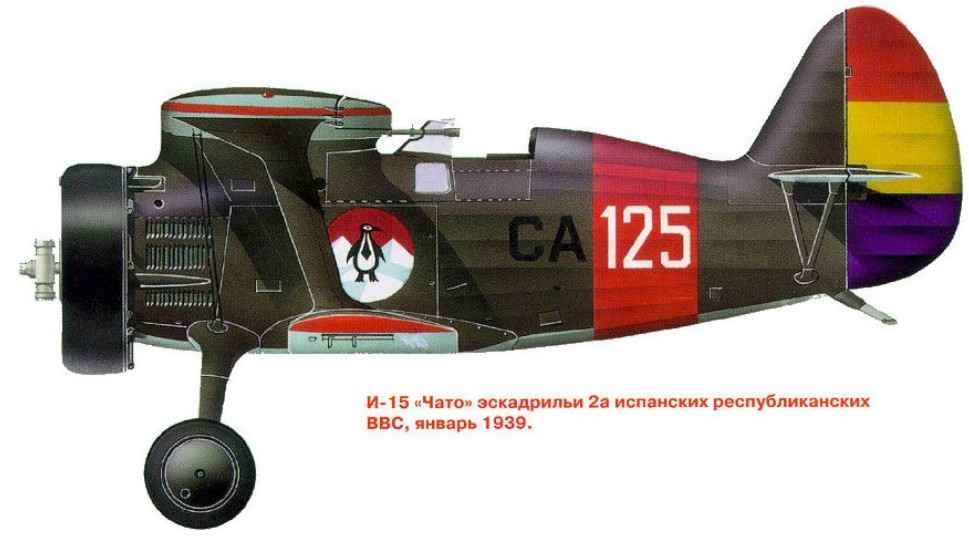
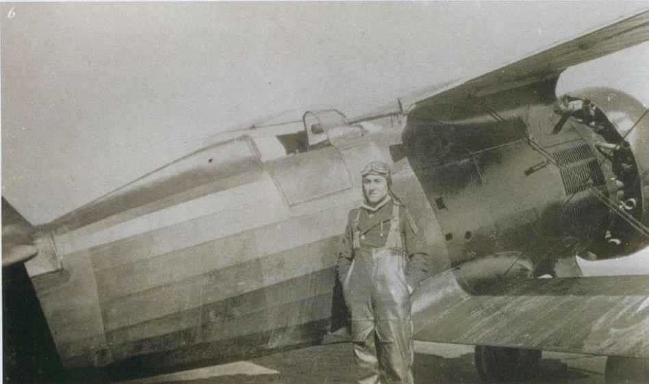
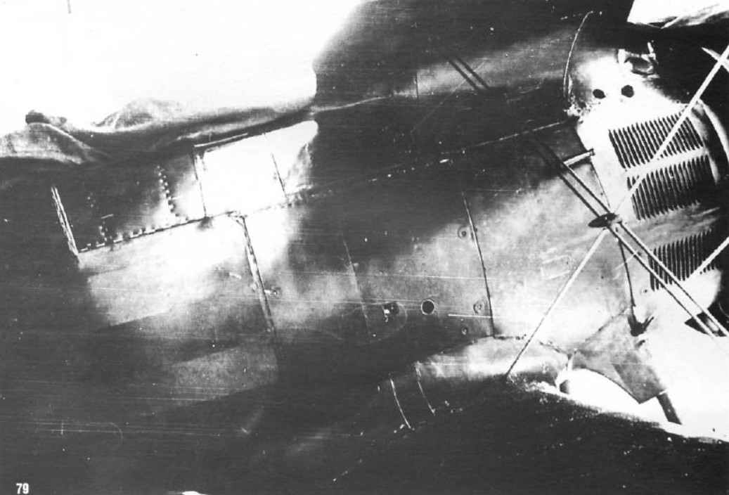
Combat use of the I-15 became one of the first Russian combat aircraft, which the Soviet volunteer pilots joined the fight with the Nazis in the autumn of 1938 in Spain. Air war in the skies of Spain showed the superiority of the I-15 over main rebel fighters – the German Heinkel He-51-A-l and Italian Fiat CR.32. The latter was faster, heavier, but a dive Italians often moved away from violence And 15’s. Usually the pilots “Fiats” tried suddenly hit on the “Chato”and walk away. On the other hand maneuverability “Fiats” were much worse than I-15. However, if “Chato” came under fire of heavy machine guns “Fiat”, the chance to continue the fight on equal was a little. On the other hand, four ShKAS-caliber rifle and could not bring much damage to the Italians. Usually Republican pilots tried to hit the radiator of the enemy.
 In the sky of Spain-15 first met Me-109 of the Legion Condor. The pilots drive around used the tactics of sudden attack and care regardless of whether they managed to hit the enemy aircraft. Chance to win the Me-109 from I-15 there was almost no..
In 1939 the conflict on the river Halkin – Gol, our pilots met in combat with the Japanese. The main indicators-15 was superior to the Japanese fighter biplane Ki.10 (in the USSR it was called I-95). However, the first battles And-15 with a Ki-27 Nate (And-97 – monoplane firms Nakajima) showed superiority of the latter.
Time-15 have expired, replaced by faster and better armed aircraft
Due to the high fighting qualities of the I-15 has gained a reputation as the strongest fighter maneuvering. Paradoxically, the recognition to And-15 it after it was removed from production (in the years 1934-1936 built 3 84 aircraft).
In Spain-15 built under license in 1938-1939, there were produced 237 aircraft, of this total, 96 were not fully secured by engines and weapons. After the civil war, And 15 were in service with the Spanish air force until 1954 as a patrol and training aircraft.
 GENERAL AND TECHNICAL DATA SERIAL AND-15
The scope of the upper wing — 9,75 m
The scope of the lower wing — 7,50 m
Length of flight line — 6,10 m
The height in lines of flight — 3.20 m
The area of the upper wing — to 15.65 m2
The area of the lower wing — 7,90 m2
Distance between plans — 1.40 m
The empty weight of the aircraft -964,6 kg
 Normal boot — 408,9 kg
Flying weight -1373,5 kg
Track chassis — 1.60 m
The size of the main wheels —700х100мм
The diameter of the propeller -2,90 m
Type of engine —Wright “Cyclone” or M-25
Engine power —730л.with.
Typing 5000M — 6.1 m
Max speed at ground(km/h) — 315
Max speed at 3000m(km/h) -367
Max-speed at 5000M(km/h) -350
The time of turn at 1000m (C) -8
-4 weapons machine gun PV-1 7.62 mm ammunition, 750 rounds each.
Assembly instructions
 Before starting the Assembly model, You need to choose the complexity of the Assembly. Model can be assembled with the motor circuit And from a set of circles, imitating the cooling fins, but you can on a more simple scheme Used of the separate cylindrical parts. The canopy can be made transparent by applying a film, but you can just cut out paper blank. The ailerons and elevators and turning can be done moving, and the screw rotating, but can not do, just glue the model without the extra bells and whistles.
To work You need to prepare the workspace and tools. Work space can be any clean and smooth surface (a sheet of plywood or other dense material length less than 60 cm and 40 cm in width). Tools: scissors, cutter, long nose pliers, pliers (You will need them for thick cardboard, and wire), glue the paper and glue transparent parts “Globus” or any other suitable for this work, awl, wire thickness 0.8-1 mm in a plastic shell, needle or pin with a head, a metal ruler with a length of 30-40 cm, sandpaper and toothpicks. To build the model is applied to the block method.
Parts list
 1-:-1B, the axis of the propeller with the ratchet; 2, 2A Carter razpredelnica; 3->3rd – block; 4 -:- 4G – cylinders; 5 – shrouds the valves; 6 – unit accessory; 7-reducer; 8, 8A-fairing; 9 -:- 9Ь – propeller; 10 – candles; and 11,11 – exhaust pipes; 12 – suction pipe; 13 – cooler; 14 -:-15 -frames of the wing and engine compartment; 16 -:- 17 – patterns of connections of frames 14,15; 18 – bow section; 19 section of the engine compartment; 20, 21 – sections of the cab; 20*, 21*- -details of inside of the cab 22 of a tail section; 23 – gargrot; 24 decal emblem 2A squadron of the air force RI is inserted in the drawing det. 19; 25,25 a – ring Townend; 25b – bonding ring Townend; 26 – instrument panel main; 26a – instrument panel ; 27 – cabin floor; 28 – guide; 29 – the pedal; 30 -pilot’s seat, the front part; 30A – pilot’s seat, back part; З0b – the chair legs; 31,31 a – control knob; 32 – optical sight “al’dis”; 32A – tubes of the sight; 32Ь – duplicating ring sight CP-5; 32C – scope mount; 33 – the canopy; 34,35 – frames of the cockpit and the tail section; 35A headrest; 36 – handle recharge of the lower machine guns; 37 machine – gun pipe; 38 – footboard; 39 – mask to the front and rear of the center section; 40 – plating of the left door of the cab; 41 – cladding right door cab; 42 – glass side-lighting of the dashboard; 43 – harness belt top; 44 – cross harness belt; 45 – lower wing; 46 – the forward part of the fairing of the wing; 47 – keel with rudder; 48 – stabilizer and the Elevator; 49-fairing of the keel; 50 – front wings; 51 – the lower part of the landing gear; 52, the upper part of the landing gear; 53,54 – gluing the landing gear to the fuselage; 55 – top wing; 56 -:- 56с – wheel; 57 – Venturi; 58 -crutch; 59шаблон of the upper wing; 60 template bottom steal; 61 -rib of the upper wing; 62 – rib of the lower wing; 63 – rib of the upper wing; 64 – rib Aileron; 65 -spar upper wing; 66 – spar lower wing; 67 – stabilizer; 67a -mount stands for stabilizer; 68 – pocket attaching struts to the fuselage; 69 – rear view mirror; 69A – mirror housing; 70, 71 – lining. Details 14,15,34,35,56 a,35A,59,60,61,62,63,64,65,66 and 6+glued to cardboard with a thickness of 1mm
 Assembly engine compartment and the bow
The engine compartment and the bow section is assembled from parts: 14 -:- 19.First assemble the skeleton of frames 14,15 and 16,17 connection patterns, as shown in Fig.3 then assembled the skeleton of the paste section of the engine compartment 19. Before the label section of the engine compartment (19) it is necessary to bend along the fold lines. Last attach the bow section, which is combined with a motor section line grids of the hood .
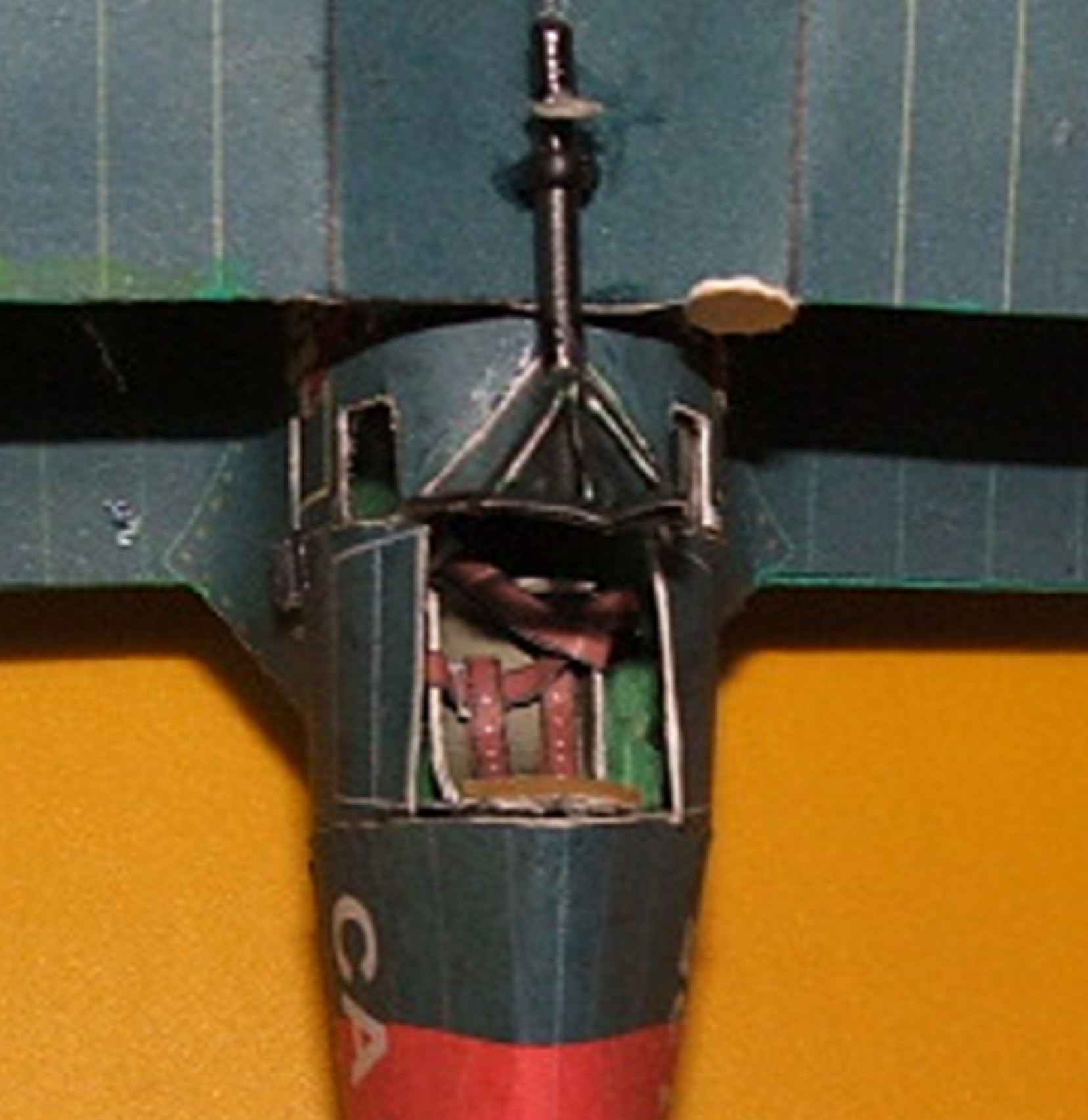
Assembly of the cockpit
The cockpit is assembled from parts: 20,21,20*,21*,26-:-31,34,36,40-:-44. The order of Assembly shown in Fig.4.
 The wings of the instrument panel must be bent at an angle of approximately 120 degrees relative to the middle part, set the instrument panel on the frame 15 with a slight slope to the floor of the cab. The pilot’s seat is assembled from two parts: the front and back, it is joined by the legs and put the seat belts (Fig.4с1). The pilot’s seat is glued back to the frame 35 and legs to the floor of the cab. On the floor before installing in the slot of the frame 15 fixed: pedals, control stick and the handle reloading of the guns (Fig.4b). Glazing the side Windows of the cockpit can be made from a transparent thin(0.15 mm) film, such film is used in a variety of containers. Hang the cab interior parts, 20*, 21*. Doors from inside the cab hang plates 40 and 41.
Assembly of the tail section
The tail section Assembly is shown in Fig.5 and at its Assembly should have no difficulties. The fairing is glued after Assembly of the partition and installing it in the frame 35. The frame 35 is bonded headrest 35A, for emphasis, the headrest can cover a piece of cloth.
The Assembly of the lower wing
Assemble the frame of the lower wing, as shown in Fig.6. When installing the parts on the fuselage, note the line set, which are shown by dashed lines in det. 19-20, the two halves of the wing are reduced exactly in the center. Attach the wing fairings to the fuselage close and glue the forward part of the fairing.
The Assembly of the upper wing
 Assemble the frame of the upper wing, as shown in Fig.7. How to build movable ailerons is clear from Fig.7a and 7b. With wire you need to carefully remove the insulation without damaging it, a metal wire to clean coarse-grained emery paper and rubbed with a graphite stylus soft pencil, and then cut the insulation as shown in Fig.7b and put it on the wire. Make sure that the insulation is scrolled freely on the wire and with the help of gluing to attach the hinge to the wing and ailerons. The gap between the wing and the Aileron should not exceed 0.5 mm. Install the upper wing to the center section, as shown in Fig.7C. Install the rack wings to the designated location on upper and lower wing.
Assembly of the tail
The empennage consists of a fin, rudder turns (det.47) and the stabilizer and elevators (det. 48). How to collect and build options are shown in Fig.8. If You want to make the handlebars turning, the workpiece should be cut on the line of their connection. The hinge device similar to those described for the ailerons. If You decide to build a simplified model, to give volume to paste in the details sections of the toothpick, as in Fig.8b and 8C. Install the stabilizer link (67) in the pocket (68), Fig. 8E.
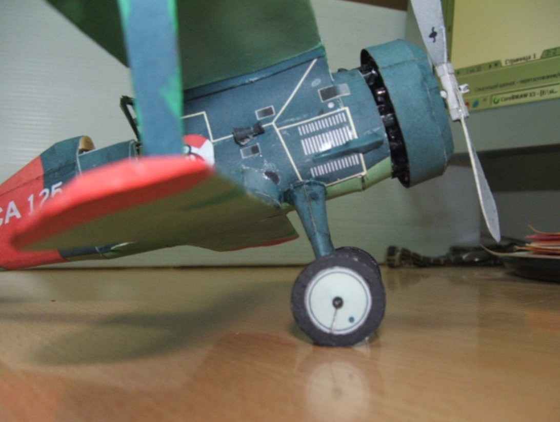
Assembly chassis
 Chassis consists of the parts: 51,52,53,54,56,56 a,56b,56с. Glue the top (52) and bottom (51) of the rack, lower rack insert inside the top and glue both parts together. Line bonding is indicated on det. 51 the dotted line. Seal the top hole of the upper rack 53 gluing the coloured side inside, stick to it as gluing 54 and set on the fuselage at a designated place for it in children. 19 ( engine compartment). Assemble wheel parts and 56.56 per,56Ь,56с, if You want to make the wheels spinning, inside: glue the landing gear wire with a diameter of 1 mm. and fold protrudes 7 mm from the rack, the end at an angle of approximately 120 degrees ( specify angle when installing the wheels on the axle, the wheels should be perpendicular to the wing). The tip of the wire sharpened needle file. In the center of the wheel drill a hole with a diameter of 3 mm, insert the piece of foam and attach to the axle. To the rear of stick crutch (58), the model is put on the table and align the installation of the wheels.
Engine Assembly
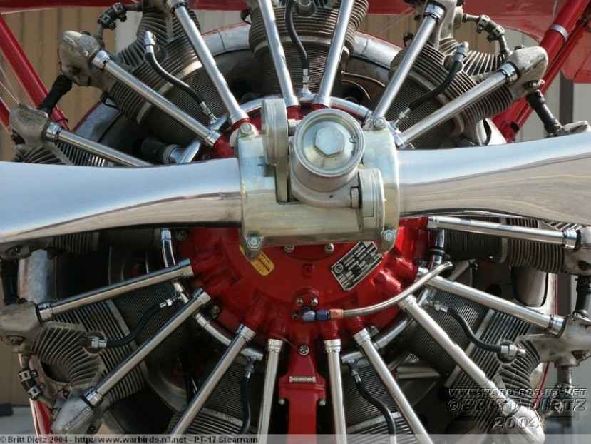
 Engine Assembly is the most time-consuming part of the model. Variants of the Assembly shown in Fig.2. The first and second embodiments have a common part and differ in the presence of cooling fins. Consider the Assembly of the first embodiment.
The cut parts 4b-:-4P placed them consistently in the center on a thin pin sticking together. The cut parts 4y-:-4z, 4y*-:-4z*,bend their edges at the fold lines and glued them on opposite sides det. 4P each other at the bent connecting edges (Fig. 2 A). Under option B, the cylinder is assembled from two parts: 4A* and 4b*. The housings of the valves (5), the lower part of the cylinder (4), gluing 4A, spacer 4q are the common parts for both versions. Craftsmen offered item 4A* wrap a thin wire or thread turn to turn the same way, too it is possible to simulate cooling fins. After assembling the cylinders, and their 9 pieces,you can start assembling the crankcases engine and gearbox, the order of Assembly which is shown in Fig.2 to the left. 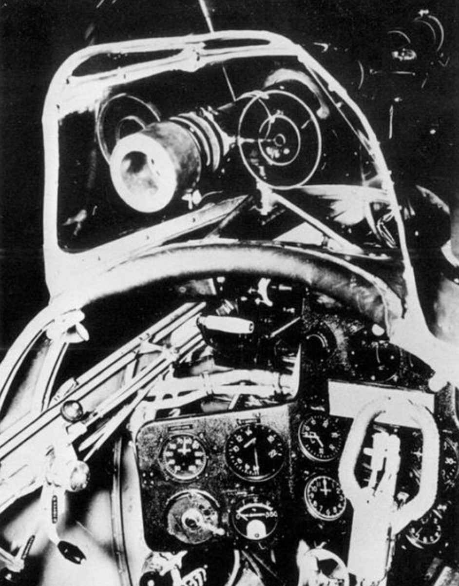 Assembled the crankcases and gearbox connected gluing the parts 3 and 6 observing the alignment of the parts. For details see set collected early cylinders, given that the angle between their axes is 40 degrees. Of the workpiece 10 do candles, for this det. 10 without cutting a collapsible tube, glue the edges, let it dry and only then cut into 9 pieces. Candles are glued to the cylinders in the places marked with a white dot. To the outer tip of the candle stick the end of the thread inserted between the parts of the early ZS and ZS*, which resemble wire. Thread should be colored: blue or yellow. Of the workpiece 11 in the same way to manufacture exhaust pipes and glued them to the cylinders from the back side under the left valve cover, billet 11a to glue the top pipe of the cylinder, it is longer than the other and has a curved shape. Tube suction nozzles manufactured from det. 12, they have “G” shape and fastened under the right valve cover, and the lower end of the part 6A in the places marked with a black circle. Of blanks 5A to glue the tube to the valve tappets and install them on the engine (Fig.2). After securing the engine oil cooler 13, the engine is ready to install in the engine compartment. The tappets can be made of tinned wire with a diameter of 0.5 mm. Manufacture of parts 37 gun tube and insert the edges of the upper cylinder, which will be considered first, after the third and before the seventh counting clockwise. Assemble the parts 8 and 8A of the engine fairing and put it on the engine aligning the slot in the fairing with oil cooler. Of the parts 25, 25A and 25Ь collect Townend ring and secure it to the engine.
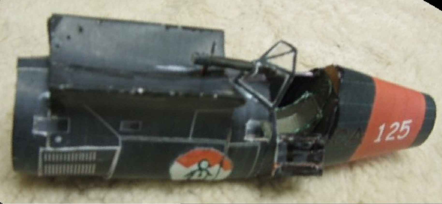
The canopy, the sight, propeller, Venturi and mirror brace.
 The canopy is assembled from items 33 to make it transparent you need not carving out the details from a sheet of carefully cut glass lantern, then glue under it is a thin transparent film and cut detail together with tape, bend at the bend lines and stick the cab in a dashed line. Optical sight “al’dis” assembled from parts 32 and 32A. Glue the tube from the part 32, insert it into the hole of the canopy, the edges stick tubes 32A and drop a DAB of paper glue in the holes of the sight, after drying, the glue perfectly imitates glass. Secure the telescopic sight on the center 32C mount and attach the backup ring sight CP-5 (det.32b). Detail 32Ь very small and cut it out carefully.
 The propeller consists of parts: 1,1 a, 1b, 9, 9a, 9b. The blades should be given a convex shape wkleic inside wire diameter of 1 mm, after bonding, expand the blades relative to each other. The screw Assembly shown in Fig. 1. The screw is rotated to the axis (1) insert the pin, and under item 2C, when assembling the engine, put a piece of foam or cork. Stick a pin in the cork – screw will rotate.
The Venturi creates a vacuum in some measuring instruments, it is assembled from two parts 57, which are rolled into long and short cones and glue at the narrow part, the tube is fixed on the right side of the engine compartment. On some aircraft I-15 Spanish Assembly set rear view mirror (det.69 and 69A), the Mirror is set on the right edge of the center section of the canopy. To give the authentic view detail 69 to paste over foil
Braces not included, because it is made of thread or thin twisted wire. Installing braces is clearly visible in the diagram Fig.1 and the photographs of the aircraft.
Check if You have “extra” parts. Success!
The materials to build a model of a FIGHTER-15 (download)
Recommend to read
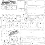 TRAIN ON THE TABLE
A train consisting of a locomotive with a tender car, napep-ing tanks and trucks built in the circle of railway modelling road station of young technicians of the North-Caucasian... THE LEG MODULE ON THE ENTIRE SET
In the manufacture of handmade furniture is particularly advantageous to find a solution component structures, which visually unifies the disparate objects in a single set. It is often...
