A vehicle’s electrical system can be supplemented with a device whose schematic and wiring are within reach of even a beginner. This device is a controller whose value is clear: its status LEDs give constant, reliable information on the condition of the stop lamps, with minimal draw from the onboard supply.
When the brake pedal is not pressed (so switch SF1 is open), with stop lamps HL1 and HL2 good, semiconductor triode VT1 is on. Current flows in this transistor’s collector circuit, so LED HL3 on the dashboard lights up—meaning stop lamps HL1 and HL2 are OK. VT2 is off at this time, so HL4 is off.
When the brake pedal is pressed, the situation is reversed. Contacts SF1 close and turn semiconductor triode VT1 off. The associated transistor VT2 turns on slightly and lights the red LED HL4, indicating that the stop signal is working.
If HL1 or HL2 burns out, or if there is a fault in either lamp’s supply circuit, transistor VT2 stays fully on and HL4 glows red, indicating a fault.
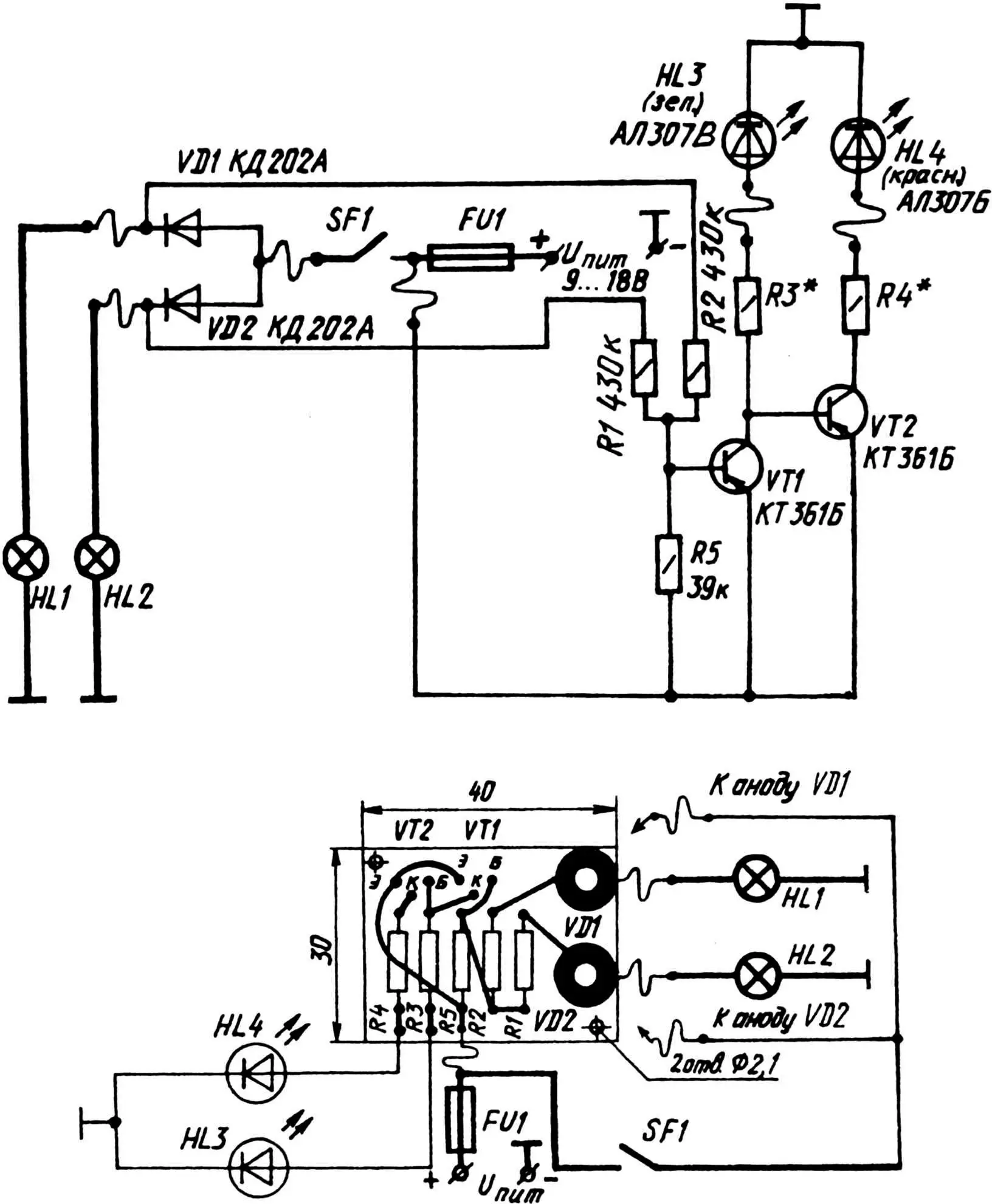
The device can do more. If fuse FU1 blows, the electronic controller also signals a fault by turning off all LEDs!
A few words on the parts used. Semiconductor diodes VD1 and VD2 provide DC isolation, so any types with parameters suited to the stop lamps will do. Transistor choice is wide; for example, the common KT361 B can be used. For status indicators HL3 and HL4, AL307V (green) and AL307B (red) are suitable. If desired, they can be replaced by a single bicolor LED (e.g. ALS331A or ZLS331A). Bright incandescent lamps with contrasting filters can also be used (with higher-power transistors than shown on the schematic).
The board is best placed near switch SF1, which is reliably linked to the brake pedal. The controller’s status LEDs, whatever their form, should be mounted on the vehicle’s instrument panel.
When assembled correctly, the controller works with little or no adjustment. It needs no maintenance—operation is stable over a supply voltage range of 9 V to 16 V!
«Modelist-Konstruktor» No. 6’2000, V. Shcherbakov
Recommend to read
 Handheld milling machine
Presented tabletop milling machine will come in handy for craftsmen who enjoy working with wood to obtain relief surfaces on workpieces, various geometric ornaments, as well as to cut... INSOLE FOR SKI…
In the simplest ski attachment over time become loose and start to come unscrewed screws. This can be avoided in the following way. Need to cut out of the walls of the plastic canister...
