 With the approach of the New year interest in the “automation tree” increases dramatically. Everyone wants to decorate a beautiful Christmas tree with garlands of “live” light-driven commands to the electronic devices. One of them is the device to create the effect “running fire” — we tell today.
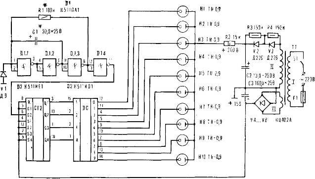
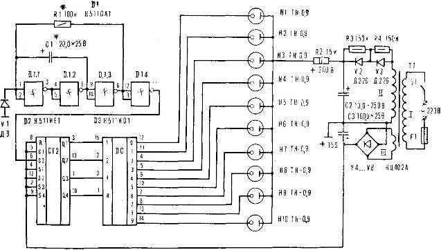
Diagram of the device (Fig. 1) consists of a generator (D1), pulse counter (D2) of decoder (D3) and power supply. The generator produces pulses of a given frequency which is fed to the input 6 of the counter pulses. With exits 3, 13, 1, 10 D2 get certain combinations of signals. They go to the inputs 15, 2, 3, 1 decoder, causing the serial connection of lamps H1 — H10.
When the values of resistor R1 and capacitor C1, indicated in the diagram, the ignition timing of each subsequent bulb is about three seconds. By varying the resistance R1 in the range of 60-600 ohms and the capacitance C1 from 5 to 100 µf, choose the switching time in the range of 0.2—20 sec.
The diode V1 is used to reduce the negative voltage on the inputs 1, 2 of the chip D1.
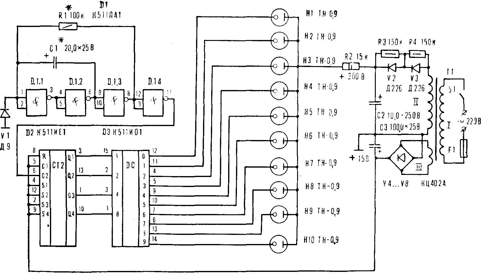
Fig. 1. A circuit diagram of the device “running fire”.
The device used fixed resistors MLT-0,25, electrolytic capacitors K50-6. The diode bridge КЦ402А possible to replace individual diodes D226.
Resistance “equalizing” resistors R3 and R4 is in the range of 100-200 ohms.
The voltage of the winding II of the transformer T1 depends on the type of used lamps. For TN-0,85, TN-0,2-1, TN-0,5 MN-11, MN-7 is 100 V and for lamps T-0,8 T-0,25 — 140 V.
To one output of the decoder, you can connect several lamps in parallel, provided that their total current will not exceed 7 mA. And consistently with each of them it is necessary to connect a ballast resistor resistance of 10-30 ohms.
Power transformer — from any low-powered tube radio. With increasing winding remove part of the windings to obtain the desired voltage and instead of doing the filament winding to the 15th Century.
Insights 7 circuits D1, D2, and D3 connected with 8 “General” tire and 14 D1, D2, D3 and 16 with the power source .+15 V.
The switch is assembled on a printed circuit Board made of foil Micarta (Fig. 2).
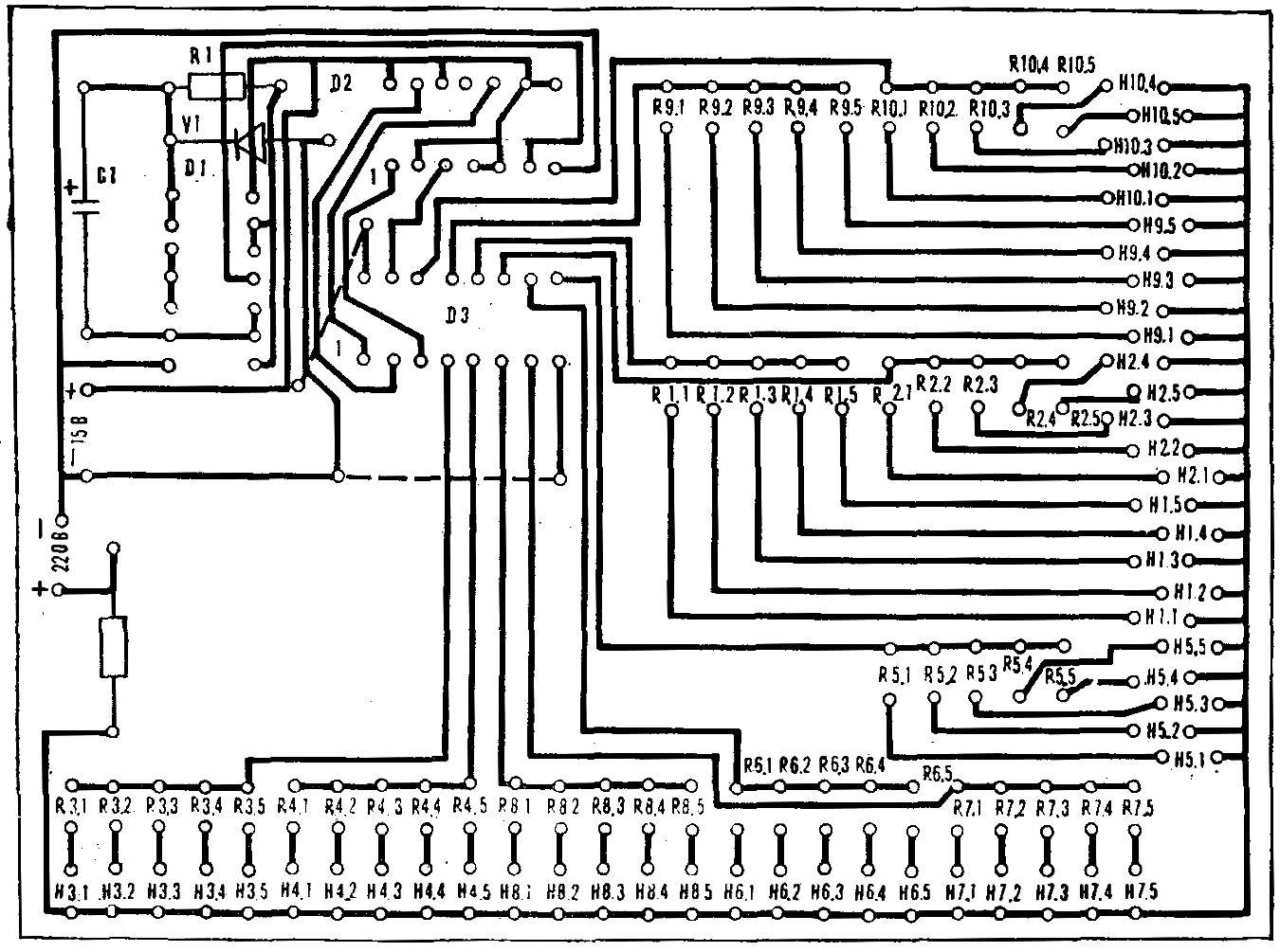
Fig. 2. Printed circuit Board device “running fire” with the location details.
A. ROGOVITSKIY, Tashkent
Recommend to read
 NO INJURIES
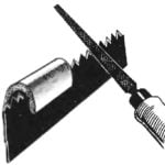
When sharpening saws with a file, if it is not docked, holding her hand runs the risk of injury from sharp teeth. To avoid this, make of a segment of hose to the loser at hand — work...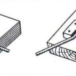 EXPRESS-TEMPLATE
Often a rigid wire or, conversely, a soft rod or a thin pipe required to give the necessary bending of a specific shape and size. Often try to do it in a Vice or just pliers that...
