 That recumbent healthy, I think, nobody will argue. Well, for fans of technical creativity it doubly useful as it allows you to gain invaluable experience before the greater constructions. Recumbent, about which speech will go, was designed and manufactured in the workshop of young technicians (syt) of our city, together with members of the group. I must say that the idea of its creation have arisen much earlier, but because the materials and most of the parts (particularly wheels) have prepared himself, at his own expense. However, the wheels and the materials are mostly picked up from an abandoned Bicycle, so that the cost was not so great.
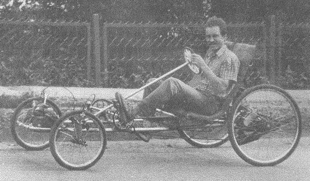
Recumbent — double, four-wheeled. Front — wheel steering, rear — wheel drive. The crew has two pedal actuator, each on their wheel.
Recumbent frame — welded, dvuhlonzheronnoe scheme. However, both the spar and the front cross member is made as one piece — the curvature of the pipe outer diameter of 40 mm from the handrail of a decommissioned city bus. The ends of the side members are folded up and together with welded thereto traverses serve as supports for the seat backs.
Between the supports of seat backs welded in rear cross member — it serves as the upper leg suspension units (springs and hydraulic shock absorbers) rear axle.
The front pillar of the seats is low portal, supported your stands on both of the spar, and also connects them. In his mid-mounted handbrake handle, and the ends of the bars — levers-shifter.
Rear axle rather unusual design. It is based on closed subframe, welded handles backrest metal beds. On the sides fixed in bearings of the axle of the drive wheels with three speed unit drive sprocket.

Double, four-wheeled, recumbent dvuhmestnoe with soft suspension on all wheels (parts of POS. 7, 12, 14, 29, 30 made of pipes with a diameter of 40 from the bus rails):
1 — front wheel (off the bike “Kama” modified); 2 — steering knuckle; 3 — steering shaft (duralumin tube Ø20); 4 — supporting strut with bushing the steering shaft; 5 — pedals (road bike, 2 pieces); 6 — wheel; 7 — the portal (steel pipe Ø40); 8 — spring rear suspension (exhaust of a moped “Karpaty”, 2); 9 — rear wheel (off the bike “Ural”, 2 PCs.); 10 — caliper hand brake; 11 — disc hand brake; 12 — frame; 13 — wheel bearing housing; 14 — beam front axle; 15 — rod; 16 — mikolina tie rod; 17 — steering gear (gear rack); 18 — seat; 19 — handle hand brake; 20 — drive chain (road bike, long, 2 PCs); 21 — the lever of switching of speeds (on a travel bike, 2 PCs.); 22 — rod for the subframe of the rear axle (area 35×35, 2); 23 — cross-member longitudinal rods (steel, circle 10); 24 — Klondike (2 PCs); 25 — rear wheel drive (2); 26 — subframe rear axle; 27 — shelf shaft bearing (area 35×35, 2 PCs.); 28 — front caliper hand brake; 29 — the traverse of the backrest (2 pieces); 30 — rear cross member; 31 the axis of rolling of the sub-frame; 32 — Dragoon (from the moped “Verhovina”); The 33 — seat base (made of anodized aluminum, the sheet s is 1.5, 2); 34 — the lining of the seat (foam, sheet s30, 2 items); 35 case (nylon fabric, 2); 36 — bracket base seat (steel, sheet s1, 4 pieces); 37 — mount base seat (bolt M6, 4 pieces); 38 — bushing-hub with the flanges of the rear wheel; 39 — М12х30 screw with washer rear wheel; 40 — threaded bushing M10 (2 PCs.); 41 — tip axis (M10, 2 PCs.) 42 — washer (nylon s3, 4 PCs.)

Rear wheel drive:
1 — Bush-the hub of the rear wheel; 2 — the subframe rear axle; 3 — the bearing №203; 4 — the bearing housing No. 203; 5 — axis; 6 — the bearing housing No. 202; 7 — the bearing №202; 8 — block of stars; 9 — the bearing number to 201; 10 — dust washer; 11 — the ratchet; 12 — unit stars; 13 — spacer distance ring; 14 — a lock ring; 15 — the locking sleeve; 16 — nut M12; 17 — dog; 18 — return spring; 19 — pin; 20 — shelf bearings; 21 — cover; 22 — the bump
The left axle is mounted (welded) disc brake. Brakes tick and act on the front wheels. The subframe is connected with the frame (or rather portal) through an oscillating axis and two oblique levers made of steel angle corner № 2,5.
Front suspension — independent with coil springs. Springs are placed into the sleeves of the axes of the steering knuckle. The suspension stroke is small, and it only absorbs small bumps in the road. Therefore, to mitigate the impact from larger irregularities on the axis on both sides of the bushings installed bumpers of soft rubber (the thick washers).
Rear suspension is “semi-independent”. Subframe suspended on springs (from moped “Carpathians”), with hydraulic shock-absorber from a moped “Verhovina”. The wheels of the car are different. Front — bike “Kama”, the rear of the bike “Ural”. But those and others — reworked: they have been replaced by a sleeve-hub a longer (two times).
It should be noted that the wheel Assembly is not easy, and to facilitate this operation was made conductor. From a sheet of plywood cut out a circle with a diameter equal to the wheel rim, and on its circumference has consolidated four rack-stop a height equal to the protruding beyond the rim part of the hub. Then the new (elongated) sleeve secured with a bolt and spacer in the center of the plywood circle and a wheel equipped with spokes — first, the needle was inserted into the hole in the hub flange, and then end in the hole in the rim and nagissa with a slight stretch. After installing all the spokes the wheel is removed from the conductor and the spokes tensioned completely with a check for the absence of the wheel “the eights”.
The front wheels swivel. The steering is homemade. It consists of a “donut”, the tubular shaft to the steering gear pinion with tie rod. The rake and the rod tip is connected via a ball joint. The other end of the pull rod connected to the knuckle of the right wheel, and from him to the left wheel goes one — mikolina steering rod. The front wheels are mounted and tick-borne workers (chassis) brakes.
Drive velomobile — pedal. The driver and passenger — each, three-speed, independent. The three speed gear is enough for movement on any terrain. But we should recognize that the unladen weight of the velomobile in the 55 kg one person when travelling uphill to pedal even on the lowest speed hard.
Foot knots carved in picking out frames older road bike and is welded at a comfortable distance from the seats to the side members. Three-speed units rear sprockets of semi — homemade, and only the asterisk is used from a travel bike. Homemade and tensioner-switch drive circuit.

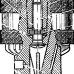
Steering rack and pinion:
1 — rail; 2 — bushing (bronze); 3 — the casing of the mechanism; 4 — gear; 5 — nut M6; 6 — cover; 7 — ball; 8 — bolt M4 (4 PCs); 9 — locknut M12; 10 — screw tip; 11 — desire (tube Ø16)

Steering knuckle front wheel:
1 — spoke wheel; 2 — the hub-sleeve; 3 — bearing No. 201 to (2); 4 — M10 nut with washer; 5 —axis; 6 — the bearing number to 202; 7 — nut M12; 8 — bushing (bronze, 2 pieces); 9 — bushing I-beam front axle; 10 — spring; 11 — a beam of the front axle; 12 — bump (rubber washer, s5); 13 — axis; 14 — clip; 15 — puck

Jig to build wheels:
1 — base (plywood s10); 2 — remote bushing (4 PCs); 3 — wheels; 4 — wheel AIDS; 5 — bushing; 6 — flange sleeves (2 PCs); 7 — bolt M10; 8 — washer (2 pieces); 9 — nut M10
Seat crew improvised. Their basis is attached at four points to the elements of the frame, made of duralumin sheet thickness of 1.5 mm. On the Foundation laid lining — foam Mat that is covered with a cover of bright nylon fabric.
A long journey used to take a plastic Cape, which hid other necessities stowed in the trunk. The trunk was represented by a grid, stretched between the side members and a beam front axle in the nose of the crew (not shown, but visible in the pictures).
I note that to connect the various elements of the frame and suspension into a single structure used household welding machine, and most small parts (axles, bushings, etc.) turned on a small school lathe.
I confess that other than for travel on official business, used recumbent for two seasons (warm season) for travel to work and back home. Besides, the weekend did it with my wife or brother camping.
After two years of operation in the recumbent, specifically on its rear left wheel was installed, the engine D-4 and began him another “life” as a “motomobile”. This variant of the recumbent converted into Motueka shown in the photo.
A. MATVEICHUK, Zavodoukovsk, Tyumen region.


