
 Remember, what is the simplest electrical circuit? The galvanic battery and light bulb connected by conductors through the switch (see the article “Ohm’s law” in the “M-K” N2 9, 1978). If such a circuit connection line length of about 30 cm to bring a compass, its magnetic needle will tend to become perpendicular to the conductor (Fig. 1).
 The same conductor position below the compass. Again, the magnetic needle tends to become perpendicular to the conductor but rotates in the opposite direction.
Now you have seen that the current is a constant companion — magnetic field.
Instead of bulbs in a circuit can include a resistor whose resistance is two times less than that of the lamp. Then the current in the circuit will increase (according to Ohm’s law) in half. Stronger will be the magnetic field around the conductor. However, there is another way it boosts…
The coil from under the thread wrap 300-350 turns of wire Ø 0.2—0.3 mm in enamel or silk insulation (PEL, sew, PALSO of 0.2—0.3). You get the coil — solenoid. Connect it to the battery (Fig. 2).
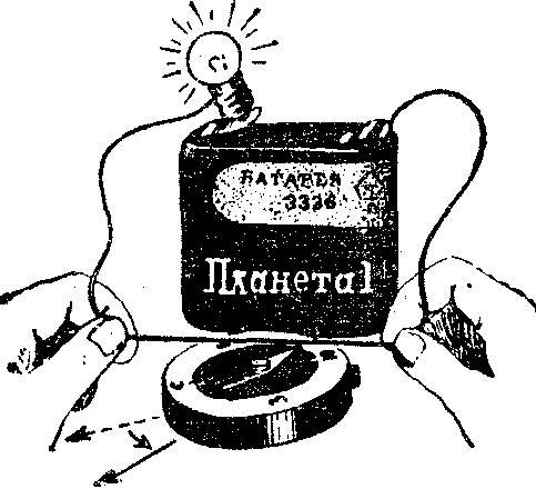
Fig. 1. The electric current interacts with the magnetic arrow of the compass.

Fig. 2. The solenoid.
It should now bring the coil to the compass as his magnetic needle immediately located along the axis of the solenoid. And react will be much more energetic.
The coil current the magnetic field of the individual coils are directed in the same direction. Merged, they form a much stronger magnetic field than single conductor.
Move to the hole in the coil steel nail or bolt — it will be drawn inside the solenoid. And playing the role of the core of the nail or bolt enhances the magnetic properties of the coil current.
By the way, the coil current, inside of which there is an iron core is called an electromagnet. Is the coil an electric current flows, it behaves like an ordinary magnet: interacts with a compass needle, attracts iron objects, magnetizing them an invisible force field.
Disconnect the coil from the battery — circuit current will cease, disappear its magnetic field and the compass will re-Orient the magnetic poles of the Earth.
Get acquainted now with some practical applications of the electromagnet. Early in the century was created buzzer — simply put, buzzer, emits a loud, intermittent sound. The device has long served to explore Telegraph Morse code.
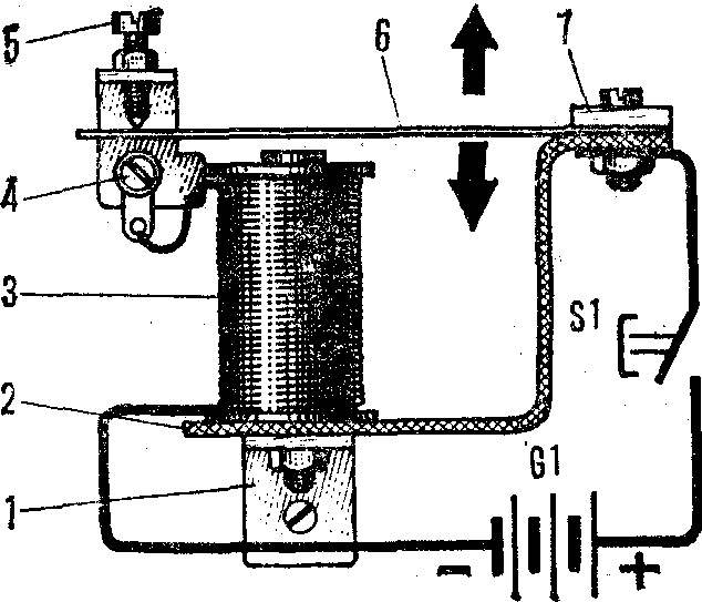
Fig. 3. Buzzer:
1 — area, 2 — clip, 3 magnet coil, 4 — breaker, 5 — adjustment screw, 6 — vibrator, 7 — insulating strap.
Buzzer design is very simple (Fig. 3), and it is easy to collect from any available materials. The bolt diameter 4-5 mm, length 35-40 mm thread two round cheeks Ø 20-25 mm. the Area between them wrap two or three layers of paper. The remaining free part of the threaded bolt clamp in the Chuck hand drill, and so made a frame to wind the winding wire of PEL or PEV 0,2—0,3 to fill. The clip-magnetic circuit bend iron bands size 100X20X2 mm. To one end of the bracket and attach the coil of the electromagnet, and the other vibrator, narrow steel spring, which emits a sound when the excitation of the electromagnet. Breaker make from the metal bracket and M3 screw with nut.
One output of a winding of the buzzer connect to the battery, the other to the front of the breaker. Now, connecting the second pole of the battery to the plate of the vibrator, a position of the screw at which the buzzer will give a loud and sustained sound.
Then add the buzzer to the two keys (Fig. 4). Includes a Telegraph station on the two posts (Fig. 5). It can help the ear to learn Morse code and the Telegraph to conduct a “conversation” between the two correspondents.
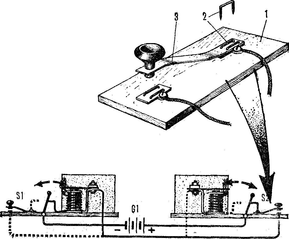
Fig. 4. Telegraph key:
1 — base key 2 — mounting bracket 3— spring plate.
Fig. 5. Telegraph station on two posts.
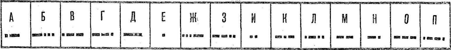
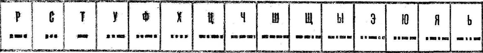
Morse Code.
Here is another application of electromagnet — electric bell (Fig. 6). Of two coils, the electromagnet attracts a spring loaded anchor with a hammer. The anchor hits the Cup of the call and then closes the supply circuit of the electromagnet. Under the action of the spring anchor returns to its original position, the power supply circuit of the coils is restored, and the cycle repeats. Therefore, while pressing call button, it rings continuously.
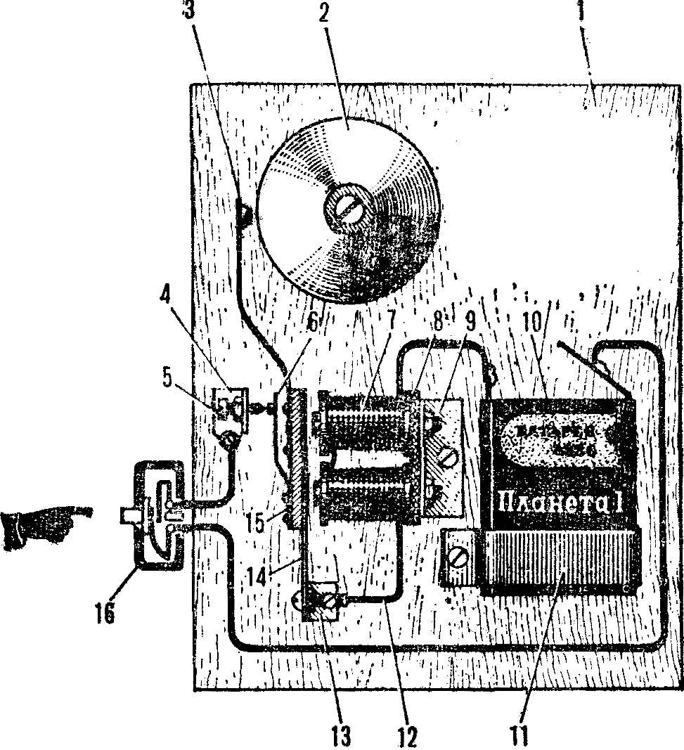
Fig. 6. Electric bell:
1 — base 2 — Cup call, 3 — hammer, 4, 9, 13 — mounting bracket, 5 — screw breaker 6 — contact spring, 7 — coil of the electromagnet, 8 — strip, 10 — battery, 11 — clip 12 — mounting wire, 14 — a flat spring 15, and the anchor, a 16 — button.
For making call you will need the two bolts M4 with a length of 35-40 mm mounted with jaws Ø 20 mm. Winding of the wrap wire of PEL or PEV of 0.25—0.35 to fill. Both coils are mounted on a steel bracket size mm. 45X20X2 Assembled electromagnet mounted using a metal bracket on a wooden base.
The anchor is manufactured from steel strips size mm. 45Х10Х2 one end, attach a thin plate (e.g., razor blade) and the spring breaker (contact plate from the faulty relay), and the second wire lever with a hammer. It is made of cut steel rod Ø 10 mm. Breaker is the metal square with the M3 screw. Cup call from the bike, an old phone or clock alarm.
The basis of the Tira remote control is also an electromagnet. From a distance of 3-5 m need to get to the center circle target small rubber ball. With a successful cast on a target signal lamp (Fig. 7).
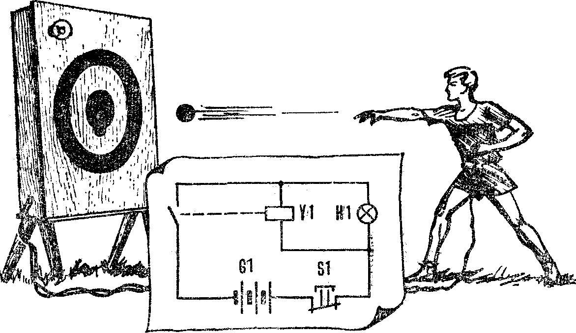
Fig. 7. Electromagnetic shooting.
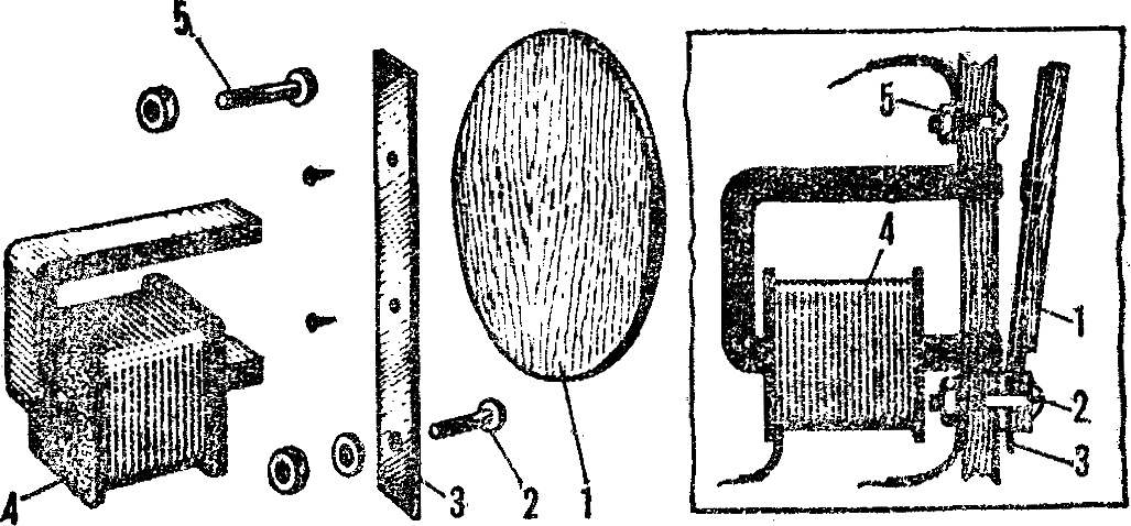
Fig. 8. Design target:
1 — movable disk, 2, 5 — M4 screws with nuts, 3 — anchor, 4 — electromagnet.
In addition to the electromagnet, the design consists of an elastic steel plate-anchor, to which is attached a wooden disk of the Central circle of the target, and two contact screws (Fig. 8). The winding of the solenoid containing 500 turns of wire sew 0,44 wound on a frame height of 40 mm, made of presspan or heavy paper. The core is an iron bar, curved in the form of the letter P. the Electromagnet installs under the center of the target on the inner side of the housing. Steel anchor along with a Central steep drive target is attached the lower contact screw to the housing so that the contact between the upper screw and the upper end of the armature remains a gap of 1-2 mm.
Upon impact of the ball on the drive plate anchor bent and touching the top of the contact screw, completes the circuit of the solenoid and lamp. Last lights, and the electromagnet attracts the armature and continues to hold it after hitting the ball as long as the button is pressed S1.
To plate-anchor not sticky, it is in contact with the poles of the electromagnet should be pasted with glue BF-2 laying of pressshpana or heavy paper.
Switch S1 can be mounted in a small box — remote control — and connect with a target two-wire flexible cord length of 6-8m.
A. VALENTINOV, A. GALIGUZOVA, Yu. PAKHOMOV
Recommend to read
 GAIN POINTS ON THE “STAND”
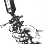
A failure to "stand" due to poor paint quality model. A crucial role when applying color coating plays spray. I tried them for twenty years are many, but none fully satisfy me. That's... HARNESS THE WINCH
A winch working in tandem with a plow is nothing new. Especially for owners of small land plots, where these rather simple and reliable constructions have already proven themselves...
