
 Instruments based on the radio. Determination of the frequency of an unmodulated source, an external signal. With the help of measuring GS you can configure any radio transmitting and radio-emitting devices in the frequency range 150 — 12 000 kHz, in the CW mode, and the mode AM or IM. In the absence of signal modulation of an external RF source (CW mode), its frequency can be determined by the method of zero beating with the frequency of HS. The block diagram implementation of the method of zero beat is illustrated.
Measuring the HS-enabled plug (lower left compartment) and also operates in the CW mode. The output of GS is connected two-pole plug short-circuited with the output I RF amplifier, the signal of the studied GS is supplied to the input. The output of the RF amplifier II direct wire connects with sockets “Star”. Thus, the signal is zero beat occurring at the resistor 27 ohms, is input to uzch, amplified and tapped through the loudspeaker.
The amplitude of the external signal must be set to within 1 mV of the control knob, measuring the HS to put in the middle position. The range and frequency of measurement of GS set in the center of the expected frequency of the external Gauss. Very slowly moving the reticle scale in both directions from the expected value of the frequency of the external GS, try to find the beats. If the frequency measurement HS changed rather quickly, then a beat will be perceived in the form of very short audio clicks low intensity or even skipped if the duration will be only a few milliseconds. Finding the beats, tune exactly to the frequency of the external Gauss. This is close to the expected frequency of the external GS very slowly move the sight first in one, then the other side. If the difference of frequencies of bearing izmeritelnoi TOS and external generator is less than the bandwidth uzch there is a high pitch sound that when approaching the values of the frequency carrier gradually replaced by more low frequency and when the frequencies of both generators are equal, the sound will disappear — this is the moment of zero beat.
Continuing slowly to move the reticle (in the same direction), again fix the separate beats — as the distance of the reticle from the point of their occurrence, their frequency will increase until they merge into increasing the height of the tone. When you move the reticle back picture sound is repeated in reverse order.
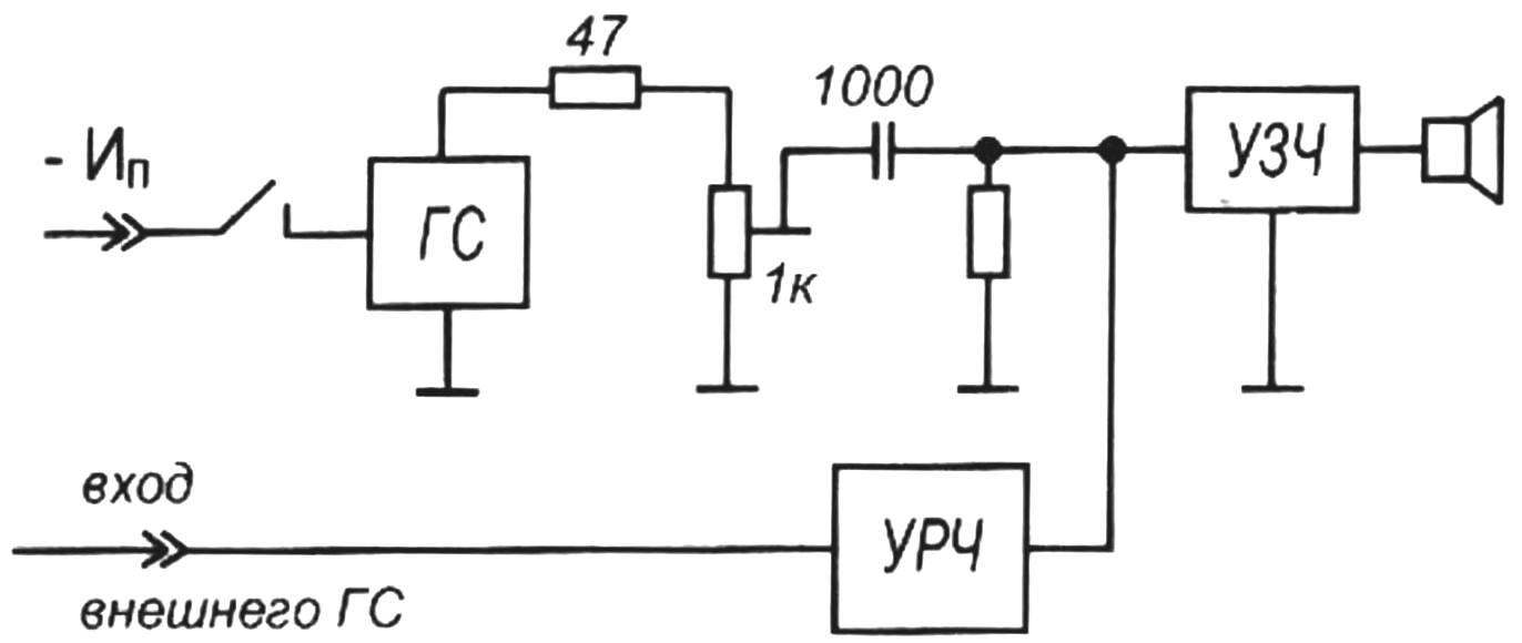
A block diagram of an apparatus for implementing the method of zero beating
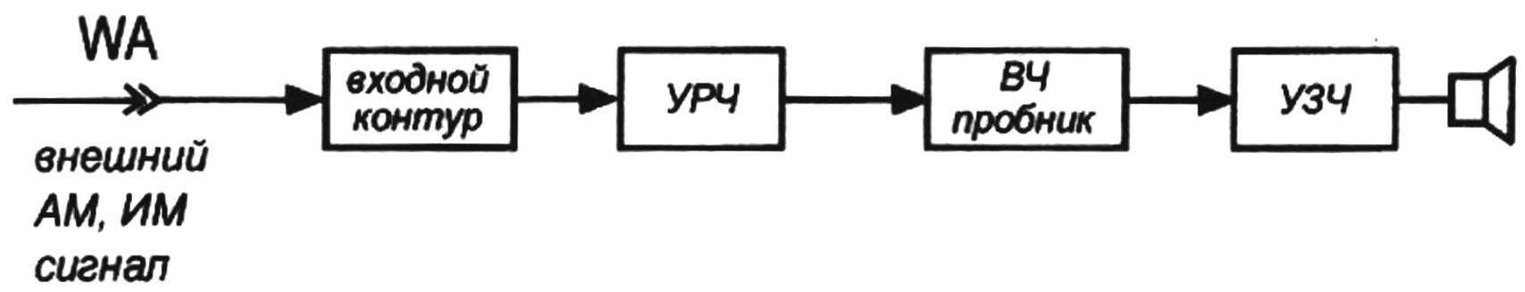
A block diagram of the device of the carrier frequency external AM, IM GS
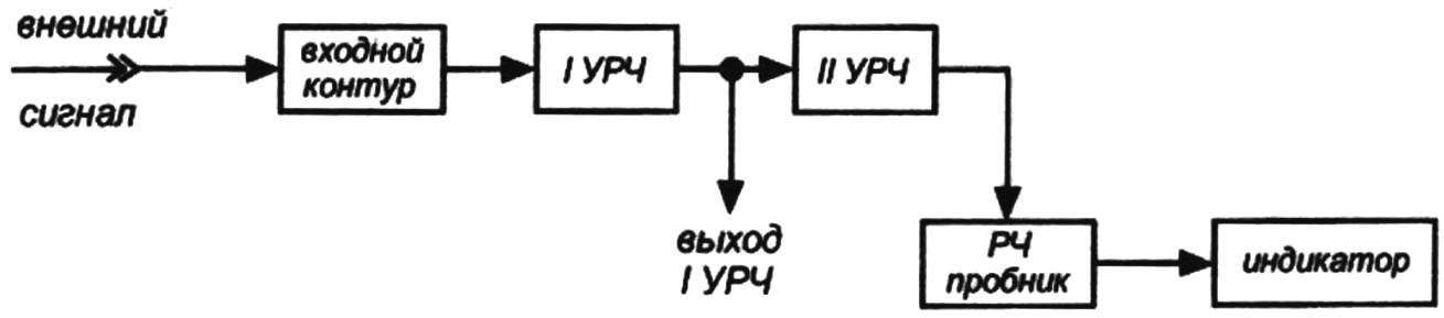
A block diagram of an apparatus for determining the carrier frequency modulirovannogo external GS
Finding zero beats and recording the values of the external frequency generator according to the TOS scale, reduce the amplitude of the output signals from both generators and look for runout on the frequencies is two times smaller and two times larger marked. First discovered the beats could occur at the harmonics of the external signal generator. Therefore at lower signal levels looking for new beats. If they are found with decreasing frequency measuring GS, and with increased amplitude, it is necessary twice to reduce the frequency of the measuring generator and try again to detect the beats.
These manipulations need to be done several times until the detected heartbeat will be monitored after another two-fold decrease frequency izmeritelnoi generator. If ampitude heartbeat gradually increases, you can be sure that the frequency at which it was last time beating the bottom, and with naibolshey amplitude, and corresponds to the frequency of the external signal. Reducing the amplitude of signals in both generators, try search beats, increasing the frequency izmeritelnoi generator. ECHR beats at frequencies of 2, 4 or more times greater than the frequency at which had been beating for the last time, barely listens or not found at all, then the value found corresponds to the true frequency value of the frequency of the external generator. If the external generator is tunable, each of the frequency scale point of this generator is determined as well.
The determination of the frequency amplitude modulated source, an external signal
By measuring TOS, you can identify the carrier frequency of AM signal or an external (test) generator. The input circuit of the corresponding frequency range (within which the test generator) is connected with a fork on the top panel to the input I of the RF amplifier. From the output of the RF amplifier II signal is fed to an RF probe. For this input plug RF probe stampeede in nest No. 4 (left middle box).
Cable RF probe connected to sockets “Star” regular panel. After the inclusion complex knob and a search for the frequency of the external generator on the maximum volume of the sound signal AM, a dedicated RF probe from an external signal. Finding a signal, try to look for him at frequencies two times higher and lower found. If the external signal is obviously rich in harmonics, the frequency range of the search need to be expanded in proportion to the number of expected harmonics. The true value of the frequency of the external source will correspond to the frequency level on the scale of the complex, in which the amplitude of the audio signal. External signal into the antenna Jack located on the side of the radio (LW and MW bands), or a regular whip antenna or a regular antenna socket (radio bands).
Configure the contours of the drive and determination of bandwidth
To work with the contours of PCH and GPCH FSS is used, operating at a frequency of 465 kHz. HRU is enabled by a plug (socket at the bottom left compartment). From the regular nests “Star” removed the plugs. Plug in the lamp panel (upper right compartment) sets the desired frequency of sound vibrations in the panel at the average of the right compartment is inserted into the cable plug which zamorachivatsja. Switch “modulation” (located on the left) is placed to the left position. Thereby the input of the HRU is activated with an alternating signal of audio frequency to amplitude modulation HRU. To the output socket HRU (left) connects the divider, the signal from one of the conclusions of which is supplied to the circuit under consideration. Regular speaker off stab with a fork, inserted into the connector of the speaker.
At the maximum sound volume of the investigated radio configured to the contours of the PCH amplifier. Varying the frequency GSC in the frequency band uzch studied radio at the hearing estimated the signal level at its output. If the subjective assessment of the strength of sound at extreme frequencies corresponding to the boundaries uzch studied radio, changing very little, so the bandwidth of the drive circuits corresponds to the frequency band reproduced uzch radio. When you find that the edges of the frequency range uzch radio the amplitude of the sound waves is significantly lower (2 — 3 times or more), you must configure the contours of the Ombudsman function, using known methods. If the test radio no amplifier stages, it is possible to use HRU in the CW mode and using the indicator to make a comparative assessment of the level of the signal with a frequency of 465 kHz as it passes through the investigated cascades. While GSC is switched off, the signal in the CW mode is input to check the cascades (cascades), and the output of the cascade, through the RF probe connects to UPT boxes. The setting of the cascade are the maximum power the LEDs.
Determination of the frequency of unmodulated signal to an external source
By resonance of the measuring amplifier can also determine the oscillation frequency of the external CW source with the use of the indicator. With five-pole connector plugs and set the desired frequency range, the drum PD is rotated to the required position. Thereby to the input of the RF amplifier is connected an input circuit for LW, MW or KV range. To the output of the RF amplifier connects the RF probe, a universal console — to the complex, cord of the indicator to the output of the RF probe. External signal is transmitted to the corresponding antenna input. Rotation of the tuning knob, on the maximum luminosity of the led configuring the input circuit to the frequency of the investigated external source. If the external source is high and the led glows very strongly, connect RF probe to the output I RF amplifier.
Determining whether the RF signal the external source, CW and AM
At a high level RF signal for an external source of oscillations is provided directly to the input RF probe and further to the input of the indicator. The strength of illumination of the led indicator, you can judge the level of the received signal. At a weak signal oscillations are fed to the input RF amplifier, the RF probe connects to the output of the RF amplifier I or II, depending on the luminous intensity of the led. Using these flowcharts can be performed independent research of any cascades of radio Troubleshooting and repair.
Work with the generator of sound frequencies
The range of the generated fixed frequencies 100 Hz-10 kHz allows the use of HSC to configure and control the various paths and cascades of audio frequency household radio — tape recorders, radios, televisions, etc. An assessment of the level of the output signal may be disturbed and you can maintain using the indicator.
With the switch SA2, the console disconnects from the chain PIC, the input and the output of which thus completing directly. Input wire UPT is connected to the output of the check device. Power of the LEDs to judge the level of the output signal. Thus, the indicator can be used to control the availability and evaluation of the signal level not only radio but also sound frequency.
Determining integrity and polarity of the diodes
Using the universal consoles you can check the pulse, high frequency and rectifier diodes with a maximum direct current up to 10 A. Check the diode is inserted findings to the panel on the front side of the console — the anode in the slot “a” and the cathode is in the slot “B”. The potentiometer (1.5 kω), with all the manipulation I put to the lowest position in accordance with the scheme of universal consoles.
Include complex, it connects the console (switch SA2 in the “On” position). In the position of the switch SA1 is “p-n-p” GSC starts to generate oscillations with a frequency of 100 Hz with a good diode. Switch SA1 is transferred to the “n-p-n” oscillations must disappear. If both positions of the switch SA1 fluctuations are present, so the diode is broken, if they are not in any of the provisions of the SA1 switch in the diode is open. When testing high-power diodes last wrapped the threaded part in a threaded socket. The second terminal of the diode through a conductor with plug and crocodile clip is connected to socket “B”. The whole polarity of the diode determined when the position of the switch SA1 in position “p-p-p”. When connecting the diode and the availability of generation to the socket “a” faces the anode of the diode. If the generation occurs at the position of the switch SA1 is “n-p-n” means to the socket “a” faces the cathode of the diode.
The definition of integrity and the voltage stabilizing Zener diode
The integrity of the Zener diode is checked when you connect the anode to the socket “a”, the cathode — to socket “B”. The potentiometer 10 ohms in any position. Generation GSC appears at a frequency of 100 Hz and with proper Zener diode and the position of the switch SA1 is “p-n-p”. While translating the switch SA1 in position “n-p-n” oscillations must be broken. The integrity of the symmetrical Zener diode, thus, it is possible to check only for the presence of breakdown: if breakdown is, GSC excited.
When determining the voltage stabilizing Zener diode connected anode to the socket “a”, and cathode to “B”, the generation frequency of 100 Hz. The 10 kω potentiometer is rotated to the left. When connected to the Zener diode press SB1 and napichi generation slowly rotate the potentiometer 10 ohms to a complete breakdown of the oscillations. The Uct value is read from the scale.
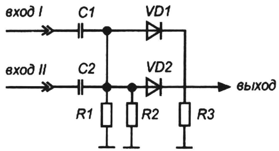
Diagram of the diode mixer
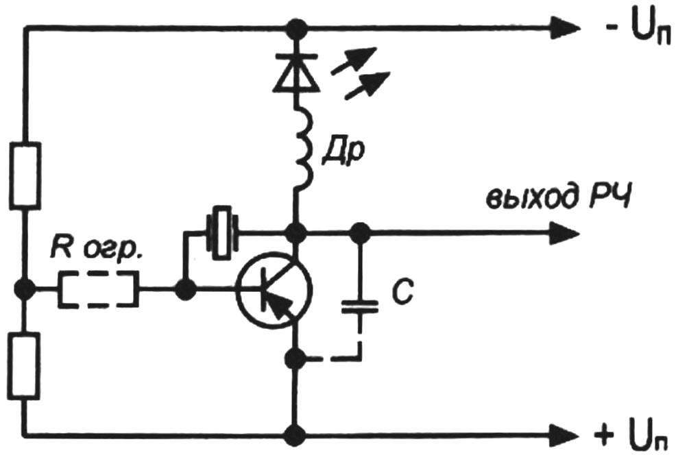
Diagram of the device for checking the operation of quartz and the serial LC-circuits
A circuit diagram of a cascade with frequency correction
In determining East a symmetrical Zener diode connecting his insights in nest “a” and “B” arbitrarily. When connected to the Zener diode push button SB1, after the commencement GSC slowly start to rotate the potentiometer 1 kOhm breakdown of generation. The Uct value read from the scale. If the polarity sign is not read, the polarity of the Zener diode is determined by the position of the switch SA1. If it is in the “p-n-p” and oscillations of sound frequency are present, then the socket “a” is connected to the anode of the Zener diode. If GSC initiated when the position of switch “n-p-n”, the anode of the Zener diode is connected to socket “B” panel.
Definition of integrity varactors
The integrity of the varactors is checked when you connect the anode to the socket “a”, the cathode — to socket “B”. The position of the switch SA1 — “p-n-p”. With proper varicap generation of sound waves is present, and when switching to popadenii “n-p-n” tempera SA1 zvukolan disappear.
Symmetric varicap is connected to socket “a” of one side of the conclusions (one by one), the average output — to socket “B”.
Determining the integrity of the SCR
The SCR is connected to Panay, while the anode is screwed into the threaded socket, and the cathode through a conductor with plug and crocodile clip is connected to socket “B”. When connected to the console and a SCR sound should be absent in both positions of the switch SA1. Handle position of the potentiometer 10 ohms at any frequency of generation is set at 100 Hz. When connecting the control electrode to the anode of SCR fluctuations GSC must be present when connecting to the cathode is absent. In the first and in the second case, the picture should not change when the polarity of the power supply.
The polarity and integrity of the LEDs
The led is connected in series in the measuring circuit directly to the power supply “-” 9 V. the potentiometer 10 kω must be in the leftmost position. Otherwise, improper connection of the led (“+” power supply “-” 9) it can fail. First determined the polarity of the led. The led is connected to terminals “C” and “e” sockets. If the led is on correctly (the negative terminal in the socket “To” plus — socket “e”), then the position of the switch SA1 is “p-n-p” it should start to glow very slightly. If not, slide the switch SA1 in position “n-p-n”. If the led is weakly lit, then the socket “a” negative terminal in the socket “K” positive. Finding the right led comes on gradually start rotating the potentiometer 10 kOhm clockwise. The led should increase. In the rightmost position of the potentiometer 10 kω the current through the led is equal to 6 mA.
Using the methods described below by using the universal consoles you can determine the integrity and parameters of bipolar transistors of low, medium and high frequencies with low, medium and high power “p-n-p and n-p-n” structures.
Definition of integrity transistors
If you know the Pinout and structure of the transistor, the conclusions of the transistor are introduced into the corresponding slots of the panel. Switch SA1 is placed at the position corresponding to the structure of the transistor. The potentiometer 1.5 kOhm is placed in the bottommost position according to the diagram, the potentiometer 10 kω — to the extreme right. Sound waves frequency is 100 Hz. If the transistor circuit — low tone, clean. If there is no sound or it is high-pitched tones — so the parameters of the transistor far from the passport or the transistor is of poor quality. In this case, you must switch to a frequency of 1000 Hz and again to check the transistor. If the sound does not — then the transistor is completely worthless.
The definition of gain
The definition of β is carried out at a frequency of 100 Hz. The potentiometer is 1.5 kω in the lower position, potentiometer 10 kOhm — in the extreme right position under the scheme. Insights check the transistor inserted in the socket panel, the switch SA1 in position check the structure of the transistor. If the transistor is intact, the generation occurs immediately. The slow rotation of the potentiometer knob to the left 1.5 kω disrupt the generation and read from the scale value β.
The definition of the insights of the transistor and its structure
If the body of the transistor of the erased symbol and unknown Pinout and structure, with a prefix you can define both. The Pinout is defined on the clusters “B” and “e” sockets. Combinations of any two terminals of the transistor are introduced into these slots serially at a frequency of 100 Hz. Need to find a combination of the two terminals of the transistor, the introduction of which into socket “B” and “e” sound is absent in both positions of the switch SA1. The findings of the collector and the emitter. Set the switch SA1 in position “p-n-p”. In the slot “B” enter the third conclusion, in nest “a” and “K” are the first two. If the sound is turned up, the socket “a” will correspond to the output of the emitter of the transistor socket To — collector in that case, if the sound is strong and low. Therefore, these two output switch. If the sound becomes weak and high, so the previous combination was correct. Change again places the findings of the collector and the emitter and mark the insights of the transistor with colored markers. If no sound arose after the introduction of the third electrode in the socket B, and the first two in the nest “e” and “K”, so the transistor “n-p-n” structure. Turn the switch SA1 is in this position and the above-described method will define the findings of the collector and emitter. Go to 1000 Hz and check that the transistor is the sound from the speaker must be strong and high tones.
A DC voltage
The potentiometer 1.5 kOhm to position “min β”, the potentiometer 10 kOhm in position “max. b”, the switch SA2 is in the “On” position, the switch SA1 in position “p-n-p”. The panel insert a reference transistor. Probes with alligator clips, connect the console to the power source, observing polarity. Connect the box to the complex. On the lamp panel using forks set frequency of 100 Hz. The speaker should be audible sound vibrations.
Rotating the knob counterclockwise voltmeter, tear fluctuations GSC. The value of measured voltage read on the scale.
Determination of the presence and level of the output audio signal, the intermediate and high frequencies
When connected to the complex console disable circuit POS toggle switch SA2. Remove the plug from the lamp socket. Handle position “ISM.β”, “izm.In” and the switch SA1 is arbitrary. Depending on the type of measurement, the indicator will connect to the output circuit of the investigated device (cascade) using the RF probe (galvanic input) or through capacity 10 — 20 THD pF (capacitive input). If the measurements it is necessary to modulate the transmitted signal, plugs lamp panel set the required frequency GSC. If the level of the signal is small (weak glow of the led) and if RF amplifier, feed to the input of the investigated signal, and the indicator will connect to the first or the second output RF amplifier.
Empowerment measuring complex
By adding a few simple knots to measuring the complex to expand its capabilities. Collected in accordance with the scheme depicted in figure 26, a diode mixer, it is possible to determine the frequencies of the two external RF generators, one of which will play the role of supporting. The range of measured frequencies can be extended up to hundreds of megahertz.
By including in the circuit the collector of transistor UPT (output indicator) universal consoles high-frequency ballasts (400 — 700 turns of wire of PEV in diameter of 0.1 mm -0,12 based on the resistor VS-0,5), we can obtain the cascade to test the operation of quartz and, thus, to the calibration oscillator frequency. RF-choke should be wound on Vysokomol resistor — 0.5 or 1.0 MW. Even better, if from the base to completely remove the conductive layer with a small block. Instead of quartz, you can enable a serial LC-circuits and check their work.
On excitation of RF oscillations is judged by the degree of illumination of the led. In the absence of quartz (LC-circuit) glow strong. If you are connecting quartz (LC-circuit) of the RF oscillations are excited, the led which is becoming weaker. If to the collector of the transistor to connect a small antenna, it can be used as a transmitter (beacon) in a radius of several tens of meters.
To determine the resonance frequency of LC-resonator or quartz (if the case is missing the value of the resonant frequency) using one of the methods described above, for example, using RIO. You may need to enable capacitance between the collector and emitter to improve the conditions of excitation of RF oscillations. For this purpose, may need to include a resistor Rогр.
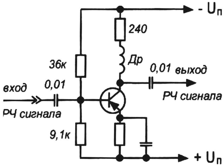
Introducing changes to the RF amplifier circuit, it is possible to significantly increase the Cu on HF-bands and thereby increase the sensitivity of a radio receiver of direct amplification. It allows to refuse from bulky antennas, and otdelnyh cases and from the ground.
To enhance Ku RF amplifier at high frequencies the collector circuits of transistors it is necessary to introduce a high-frequency inductors, and transistor ПЧ23 to replace KT361 (B, G, E). The inductance of the chokes is of the order of 2 µh.
For winding chokes are used resistors MLT-0.5 in. The value can be any. With the resistor removed the protective covering and with the help of emery stone is removed, a conductive layer (to China). The winding is a solid wire of PEV-2(1) with a diameter of 0,25 — 0,3 mm. the ends of the wires napivaetsya the findings of the resistor at the base. The regular tracks on the circuit Board (at the location of the RF amplifier) are removed and cleaned all parts of the former RF amplifier. Of tinned copper wire with a diameter of 0.8— 1.0 mm are laid bus power. Installation of the RF amplifier should be parts with a minimum length of conclusions to minimize parasitic capacitance and inductance. The inputs and outputs of the RF amplifier cascades soldered in accordance with the scheme shown in figure 10. Turn on the receiver and check the operation on all bands. If the RF amplifier will be instituted, remove the segments of the connecting cables and solder pieces of hook up wire. If this does not help, in the collector circuit of the transistor enter the filter cell RC. And the excitation RF amplifier manifests itself in the form of sounds of different amplitudes and frequencies of whistles, clicks, drones, etc. in the absence of the useful signal at the antenna, that is, if the receiver is not tuned to any station, in loudspeaker to listen weak background of 50 Hz or hissing (noise of the transistors).
By entering into the scheme is another low-frequency transistor and using standard circuit L35, L36, capacitors 240 pF to 0.01 UF, 0.05 UF and a resistor of 2.4 kω, collect another cascade drive (identical to the circuit of the transistor VT5). Capacitor 390 pF replace 360 pF in parallel to install a fixed capacitor with an air dielectric with a capacity of 20 to 30 pF. The handle of the condenser output on the front panel and provide scale. Connect the cascade to the power bus. A fixed capacitor set to maximum capacitance. Adjusting the value of capacitor 360 pF and using the existing HRU, the method of zero beating until the disappearance of sound and the scale mark “0 Hz”.
Reducing the capacity of the capacitor is adjusted, bring the value of the difference frequency to 20 kHz and make a mark on a scale of “20 kHz”. Controlling the quality of sound in the dynamics and significance of the difference frequency, apply to the scale values of the frequencies in the whole range 0 — 20 kHz. It turns out the generator audio frequency sine wave which will help to remove the frequency response of amplifiers, AF, build, curves of the bandwidth of the various radio devices, etc.
R. HAKOBYAN
Recommend to read
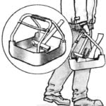 THE TRAY UNDER THE HAMMER
If you want to transfer a set of tools to the job site or just keep them at the ready is essential for this will be an easy plastic tray. These are found in hardware stores, but can be...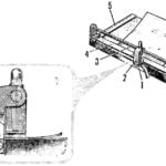 CUT… BEARING
Not find, perhaps, a car or complicated mechanism which isn't used ball bearings: they are embedded in devices and engines, airplanes, and tractors, bringing accuracy, reliability and...
