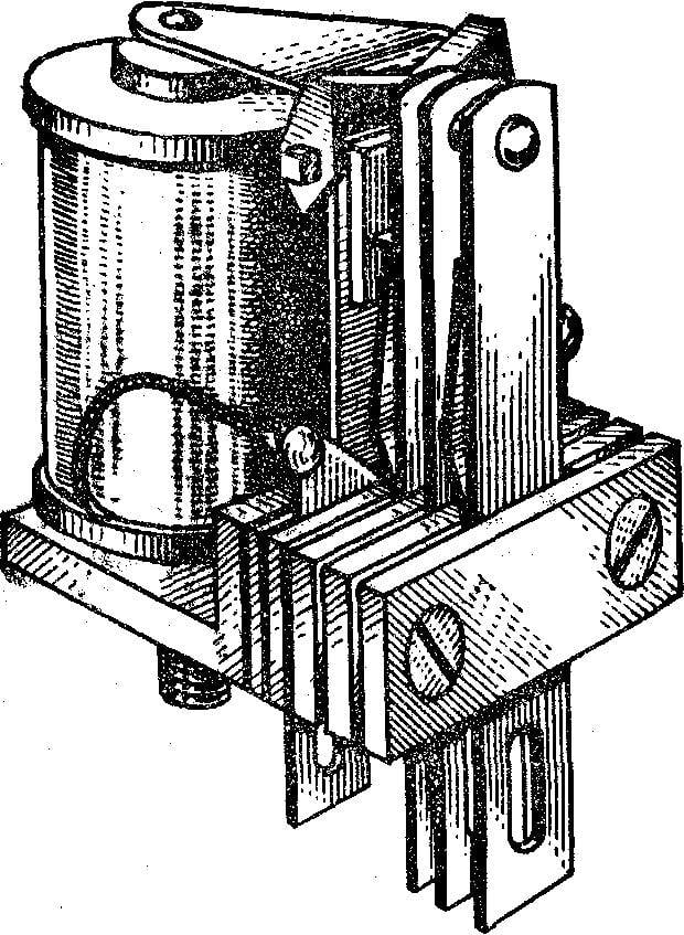
 So, you are already familiar with the electromagnet, knows how to work the buzzer and electric bell (see “M-K” No. 8 this year). But there is a large group of Electromechanical devices, the main element of which is also an electromagnet. It’s the solenoid. That’s how they are.
 For a rod of soft iron — core — fitted coil containing a large number of turns of insulated wire. On the l-shaped relay case is held by the anchor strip of soft iron, bent at an obtuse angle. The case strengthened the contact plate, closing and disconnecting supply circuit of the actuator, for example, tungsten.
While the current through the relay coil is not, the anchor under the action of the contact springs is located at some distance from the core relay. But only in the coil a current flows, the magnetic field magnetizes the core which pulls the anchor. At this point, the opposite end of the armature presses on the contact plate, closing the circuit Executive. It stops current in the coil — vanishing magnetic field, the core is demagnetized and the contact plate, straightening up and breaking the chain of execution, return the anchor of the relay to its original position,
Depending on the design features distinguish relay contact, normally closed and change-over contact plates. First, in the absence of current in the coil contact plates are open, and when the current in the coil they are closed (B). Relay with normally closed contacts are reversed: in the absence of current in the winding of the contact plate are closed, and when the winding current flows, they open (In).
Relay the third group has three contact plates (G). The average associated with the anchor and in the absence of current closed-loop with one of the extreme contact plates when the switch is shifted to the other extreme plate and closes with her.

The symbol of the relay:
A — coil, B — trailing, — NC, G — switch contacts.
Most relays have several contact groups to using current to control at a distance of several chains of execution simultaneously.
The solenoid is a complex and precise instrument. The contact plates are made of alloys of various metals (sometimes even with the addition of silver and gold), the return plate is precisely adjusted, the anchor is rotated in special bearings, insulation of the windings are tested under high voltage.
If you don’t have a relay, make them yourself. In simple structures, improvised electromagnetic devices successfully replaced the factory. Relay, as we discuss, proposed by the guys from the circle electronic House pioneers the city of Zhdanov.
On the basis of insulating material mounted solenoid and two contact stands, between which moves the plate anchor. When the winding current flows, it is attracted to the core. The anchor is thrown from one stand to another: the switch contacts.

Scheme call:
A — schematic; B — mounting.

The scheme “memory”:
A — principle, B — mounting.
And now proceed to the manufacture of relays. Made of plywood with a thickness of 4-6 mm cut out the base, sand paper and drill 10 holes in the mounting brackets (they are made from copper wire Ø 1.5—2 mm).
Take the cut wire length 250 mm, carefully align, clear small “skin” of oxides and saladita — cover using a soldering iron with a thin layer of solder, using rosin as a flux.
Cut five rods with a length of 32 mm and with a pair of pliers and a hammer to bend them into the form of the letter P. Then insert the mounting brackets into the holes in the stand and slightly asclepia jumper with a hammer. When a different height stands just trim them with side cutters.
The following part — the core. For its production need mild steel rod Ø 5 mm. Cut two blanks for 35 mm. On a lathe (it is in the school) will protocide on each stud recess 3 mm Ø or do it with a file. The end of the rod with a recess insert into the hole in the corner and asclepia. The rods can be fix on the thread, as long as they are parallel mutually and to the relay base.
To area take a plate of soft steel with a thickness of 1-3 mm (a metal called “steel 3”). It is easily magnetized and demagnetized, and for relays it is very important. Area attached to the base with two M3 screws Under them in the corner and cut the thread.
Of heavy paper or pressshpana make the frame (see picture). for winding the coil. Glue a sleeve of thin paper on the mandrel rod Ø 5 mm. And the first round of Express dry: then the finished sleeve can be easily removed from the mandrel.
Glued sleeve wrap thread and leave to dry. And while engaged in the production of cheeks. Cut along the contour of the round billet, make the center sharp knife of the radial slot and then bend the resulting tabs. Now stick the cheeks to the core.
When winding the wire pushing against the cheeks of the frame, and they can bend. So the glue needs to dry well, then the frame is durable. Don’t forget to make the side two holes for winding.
On the frame coil 2 thousand turns of wire in enamel insulation (PE, PEV, PEL) Ø 0,23—0,27 mm, using a hand drill. Wire try to put a coil to a coil with a constant tension. If winding turns uneven, between the layers lay a strip of thin paper. The findings put the winding insulation tube and secure with thread. Finished the coil wrap varnished cloth or thick paper and glue on top of a sign indicating the number of turns and mark the wires.
Anchor cut-out sheet. One end its bend, and on the other put the brackets of tinned copper wires Ø 0.5—1 mm. Crimp it with pliers and solder carefully to avoid sagging of the solder. The brackets will create an electrical contact to the anchor contact racks. For them to prepare two plates of tin with a size of 10X10 mm and two stands of copper wire Ø 1.5—2 mm. In the center of the plates you need to drill holes Ø 1,5—2 mm, and the wire bent at a right angle.

Homemade solenoid:
1 — area (steel 3), 2 — magnet coil, 3 — base (plywood S 4— 6mm) 4 — pin base stand (tin S 0.5 mm) 5 — pin rack (copper wire Ø 1.8 mm), 6 — bracket mounting (copper wire Ø 1,7—1,8 mm) 7 — anchor (tin S 0.5 mm), 8 — core rods (steel 3).

Electrical relay diagram.

Frame for winding the coil.
Now proceed to the Assembly of the relay. Since the manufacture of parts in the size of possible deviations of the alignment hole drill “in place”, that is, parts to attach to each other as they work in construction, and the holes in one part mark the holes in the other.
First select the area with the core, pushing it to the perimeter of the base. Then put on the coil core so that the conclusions were closer to the corner. Where is the flatted on the second rod, solder the anchor. On both sides of the movable end of the anchor pin nail the two stands so that between it and the core was a gap of 2-2,5 mm and simultaneously a reliable contact between one of the stationary racks. The distance between them should be 2,5—3 mm.
Finally, it remains to mount the electrical part relay: solder the coil pins and the contact plate, respectively, to its mounting rack. Moreover, the join order must be the same for all relays.
The relay Assembly is completed. Connect to the coil battery 3666Л. The anchor will be drawn — relay worked. Disconnect the power from the anchor to return to its original state.
Check now securely closed contacts. Connect the lamp with the battery to contact each and every time the relay will energize, the lamp will light up. Similarly, check and break contact.
If the contact system operates poorly, fold a fixed rack or slide them slightly. Anchor when adjusting the relay bend should not be.
Now round up a few diys with the use of electromagnetic relays. For the manufacture of the first device is already familiar to you buzzer (see “M-K”, 1979, No. 8), except for the relay, you need a battery 3666Л, bell button and two feet of insulated wire. Make connections in accordance with wiring diagram. Click on the — contact plate relay should make a buzzing sound.
Following device has “memory”. When you press the button S1, the lamp H1 and the relay actuating its contact K1.1 blocks the contact plate of the button S1. But if it is released, the relay will “learn” command is sent by: the lamp will burn until the, while using the other buttons S2 we do not turn off the power.

The scheme of the pulse pair:
A — principle, B — mounting.
To collect the pulse-pair, you will need additional relays. When you press the button S1, relay K1 and its contact K1.1 includes relay K2. It opens the supply circuit of the first relay, which, in turn, turns off the second relay. The scheme returns to its original state and the process is repeated again, followed by a characteristic sound.
A. VALENTINE, G. KOTELNIKOV


