Among the various methods of connecting three-phase asynchronous electric motors to a single-phase network, the simplest and most well-known is probably the use of a capacitor called (due to the functions it performs in this case) a phase-shifting capacitor. In this case, one has to put up with the inevitable loss of power. For an electric motor with a “triangle” winding connection, even in an ideal case, it will be 40-50 percent of the nominal value specified in the data sheet. In addition to everything, depending on the number of revolutions gained by the engine, the capacity of the phase-shifting capacitor must change.
The latter is difficult to implement in practice. They are usually satisfied with a two-stage control scheme, when the switching itself is carried out using a high-capacity starting capacitor (due to the occurrence of significant currents at the moment of starting) with its subsequent replacement with a working one with a lower rating.
When connecting the windings of an electric motor in a triangle, the capacity of the working capacitor Cp is determined by the formula:
Cp = 4800 I/U,
where U is the network voltage, V; I is the consumed current, A, which can be measured with an ammeter or calculated using the well-known mathematical expression:
I = P/1.73Uηcosφ
where, in addition to the previously given designations, φ is the efficiency, cos φ is the power factor.
As for the capacity of the starting capacitor, with a significant load on the shaft, it is selected 2-2.5 times greater than the nominal value of the working capacitor. But if the electric motor is to be operated in an underloaded mode, then both capacities should be reduced (see table). It is better to use capacitors of the MGBO type and similar ones with a paper dielectric (MBGP, MBGCh), and the permissible voltages for which they should be designed are one and a half times higher than the network voltage.
| P, kW | 0.4 | 0.6 | 0.8 | 1.1 | 1.5 | 2.2 |
|---|---|---|---|---|---|---|
| C p , μF | 40 | 60 | 80 | 100 | 150 | 230 |
| C p underload, μF | 25 | 40 | 60 | 80 | 130 | 200 |
| C p , μF | 80 | 120 | 160 | 200 | 250 | 300 |
| C p underload, μF | 20 | 35 | 45 | 60 | 80 | 100 |
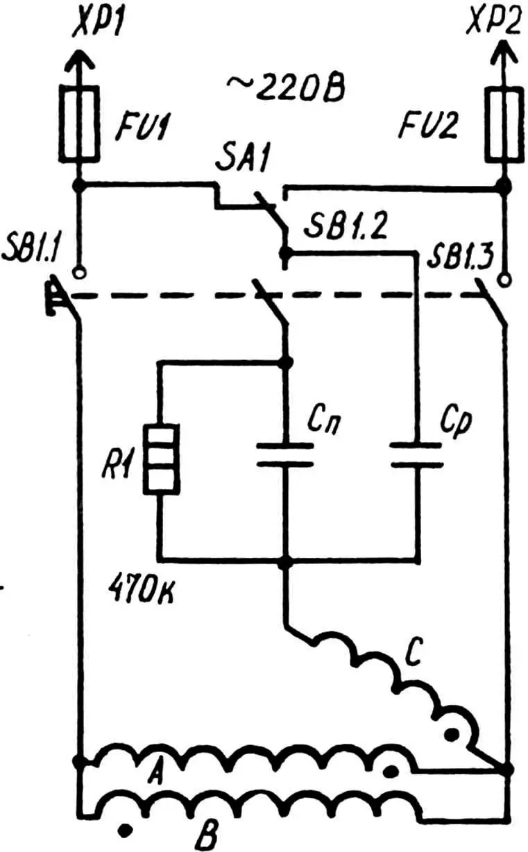
A typical circuit for switching on and operating a three-phase asynchronous electric motor with such capacitors usually also contains a special shunt — a fairly powerful resistor with a resistance of 200-500 kOhm, through which the charge from the disconnected “starter” will flow. SA1 is a toggle switch of the TV1-4 type. In this case, it serves as a reverse switch. SB1 is a PNVS-10UKHL2 starter button (for example, from a washing machine). When this button is pressed, the motor is connected to the network using parallel-connected starting and working capacitors.
After M1 picks up speed very quickly, SB1 is released. The contacts SB1.2 open, but the others remain closed until there is a need to stop the engine – this is the design feature of the PNVS-10UKHL2. That is, in the operating mode, Cn is disconnected from Cp, which is what was required to be achieved.
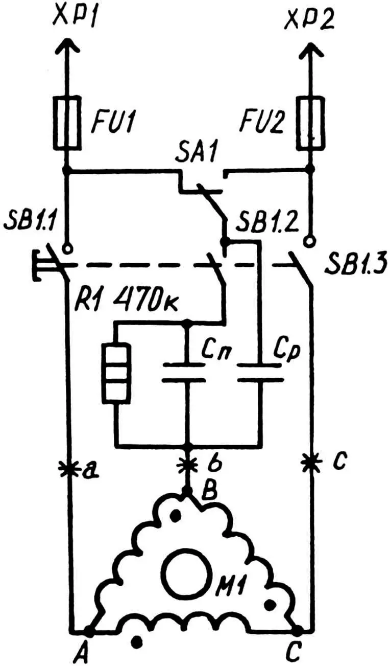
Sometimes you have to deal with the fact that SB1.2 does not move away when the button is released. Well, you need to intervene and make everything work properly. For example, put a washer under the contact.
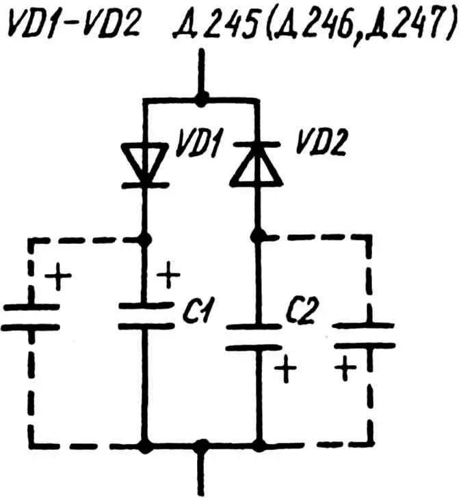
It is more difficult if you were unable to obtain paper capacitors for the starting circuit. Of the high-capacity ones, for example, you could only get electrolytic ones. To use such capacitors as “starters”, there is a special connection scheme – with semiconductor diodes D245 – D247 and similar ones that can withstand a reverse voltage of at least 300 V and a direct current of 10 A. When working with a high-power motor, the diodes are paired and installed in each of the arms on heat sinks. Otherwise, there is a risk of breakdown of the semiconductor devices. Then alternating current will flow through the oxide capacitors, and the “electrolytes” can heat up and rupture.
For the same reasons, by the way, it is not recommended to use electrolytic capacitors as working capacitors. After all, the currents flowing there are considerable, and for a long time. Not every “electrolyte” is able to withstand such a difficult regime for it.
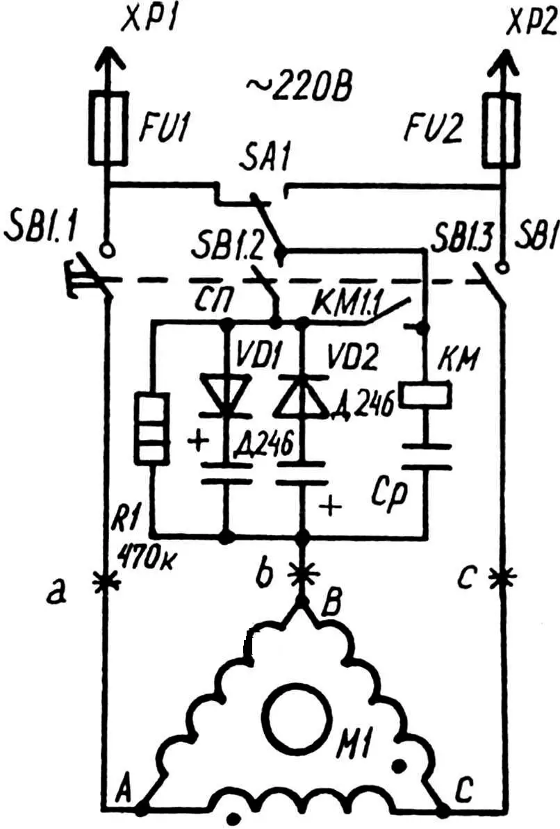
If the electric motor is to operate under high dynamic loads on the shaft, we can recommend a circuit where the starting capacitors are controlled by a current relay. Reacting to a change in current in the windings (i.e., to the effect of dynamic loads experienced by the rotor-shaft), the relay automatically switches on or off the “starters”, making the phase-shifting capacity larger or smaller accordingly. The business only benefits from this.
The easiest way to select the required value of the capacity of paper and oxide capacitors is to achieve equality of currents at points a, b, c. Moreover, the latter is possible with an optimal load on the motor shaft.
Among other existing schemes for connecting a three-phase motor to a single-phase network, it is impossible not to note the original solution, which allows reducing power losses to 25 percent. And all because windings A and B are connected in antiphase. Moreover, at full 220 V. The rotation voltage is determined by the inclusion of winding C. In order not to confuse anything with the inclusion of windings, their phasing is shown by dots.
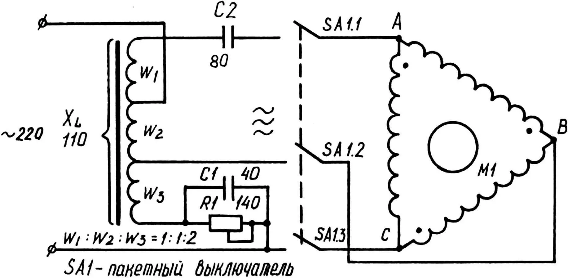
Those who like to do everything thoroughly, getting the maximum return from the equipment, will probably be interested in the circuit with a resistor-inductive-capacitive converter of a single-phase 220 V network into a three-phase one. After all, it allows the motors to operate with a voltage shift of about 120° and currents in phases up to 4 A.
The converter uses KBG (MBGO, MBGP, MBG-4) capacitors, a 700-watt resistor, and a choke on a magnetic circuit with an air gap. (A resistor made of nickel-chromium wire with a diameter of 1.3-1.5 mm, wound on a porcelain rod or tube with a diameter of 20-30 mm. A clamp-contact with a lock, moving along the winding, allows you to get the required resistance to ensure reliable operation of a motor of a given power.) Instead of the choke inductance, it is probably more appropriate to indicate its inductive resistance, which is easier to determine and control based on the readings of the voltmeter and ammeter. So, at a frequency of 50 Hz, it should be equal to 110 Ohms (the active resistance of the winding can be neglected).
In fact, the shape and grade of the magnetic core steel can be any. The main thing is to provide an air gap, and therefore the ability to change the inductive resistance of the choke. For example, the “iron” from a power transformer with a capacity of 270-450 W will be quite suitable.
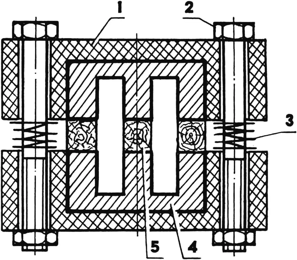
1 — half of a split frame-clamp (getinax, textolite or, in extreme cases, wood, 2 pcs.); 2 — tightening bolt (2 pcs.); 3 — cylindrical spring (2 pcs.); 4 — half of a magnetic circuit (2 pcs.); 5 — gap retainer gasket (wood, 3 pcs.)
With a magnetic circuit of 16-18 mm2 cross-section, only 600-700 turns of wire with a diameter of 1.3-1.5 mm are wound for the choke. This is a test coil. Having assembled the choke with an approximate gap, the inductance is connected to the network to measure the reactance of the prototype of the future part. Then they find out how many turns need to be added (or subtracted) to obtain the required X L .
The total number of turns found in this way is divided into three parts in the ratio 1:1:2. These data are used when winding a real choke coil, which is made on a three-section frame, the dimensions of which are determined by the dimensions and configuration of the specific magnetic circuit selected for the converter. If, for example, the number of turns found using a test coil is equal to 600, then for a “real” working choke w 1 = w 2 = 150, aw 3 = 300.
It is worth recalling that the above data is about a converter for a three-phase motor with a power of 1 kW. The parameters should be recalculated for a different power using the formulas:
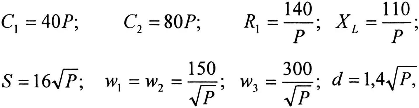
where C 1 is the capacitance of the same capacitor, μF; C 2 is the capacitance of the second (according to the diagram) capacitor, μF; P is the converter power, kW; R 1 is the resistor resistance, Ohm; X L is the reactance of the choke, Ohm; S is the cross-section of the magnetic circuit, mm 2 ; d is the diameter of the wire for winding the choke, mm; w 1 , w 2 , w 3 are the numbers of turns in the corresponding section.
And a few more comments concerning the design features of the converter and the parts used in it. The resistor, of course, should be cooled at least by convection air flows. At the same time, it is necessary to provide protection against accidental contact with it and the conductive connections. And the choke should preferably be made so that it is easy to change the gap in the magnetic circuit (and therefore, to adjust the inductive resistance of the converter itself). For example, using wooden spacers, firmly fixed with ties on the screw thread.
The converter is assembled into a single unit and placed in a metal case, the dimensions of which are determined by the dimensions of the parts and units of the structure. All electrical installation is surface-mounted.
“To cultivate my garden plot, I decided to replace the internal combustion engine on my motor cultivator with an electric one. I’ve already gotten out the 1.5-kilowatt electric motor. But it’s three-phase. How do I connect it to the network, where there’s only one phase and a “zero”?
N. PARIN, Kursk region.”
“I heard that for the operation of three-phase electric motors in a household network, DIYers use phase-shifting (but not electrolytic) capacitors of large capacity. To what extent is this true?
V. KULIKOV, Dnepropetrovsk”
A. KUKHARENKO, Grodno, Republic of Belarus
Recommend to read
 Crimean commuter trains
For several years now, Sevastopol inventor Dmitry Chulkov has been constructing electric vehicles. One of these is a universal modular chassis, equipped in the base configuration with a...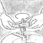 BELOW NAVIT SPRING
Using just two wooden bars, metal bars, vise and elastic steel wire, we can quickly produce the spring. Its length depends on the number of turns around the rod, operated by a bunch of...
