 If during the day to measure the mains voltage, the voltmeter each time will be different. This is due to you can enable or disable individual power consumers, changing mode of operation (in accordance with the work schedule of production, process flow, etc.), that is, change the values of loads that cause instability of voltage in the networks.
It would seem, what’s the difference — 220 To the network or, say, 250? Meanwhile, all consumers, both household and industrial, designed to operate at a strictly determined value of the supply voltage. Any deviation from this value lead to a drastic reduction of the service life of electrical equipment, reducing its effectiveness.
For example, increasing the voltage by 10% from the funeral service life of filament lamps is reduced by almost 70%. And if the voltage drops by 7% the process of annealing of workpieces of non-ferrous metal in a foundry of the plant lasts for 5 hours. instead of the estimated three. As a result, annual damage from lengthening process, is a thousand.
No less insidious invisible enemy wielding in our own apartment where you work different appliances. Take, for example, television. If due to the increase in the filament voltage of the lamps, the temperature of the cathode will increase by 3%, reduced by about half their lifespan. And first of all go down the tube.
Permissible limits of voltage fluctuations in electrical networks is strictly regulated by GOST 13103-67 most consumers are ±5%- current requirements make it increasingly necessary to limit such strict limits. In practice, however, to remain within the boundaries of these parameters is very difficult.
Mains is a complex, networked dynamical system with a mixed load and with varying voltage levels at various points. Therefore, the voltage often adjust every single end user or group of consumers. But the controls are very complicated and expensive. For example, a device for switching the terminals of the transformer operating under load depending on the power of the latter is 3-9 thousand RUB Quite obvious that such devices can only install PA major substations. And even then directly from the consumers of network stability will be unsatisfactory.
There is another factor greatly influencing the level of voltage. We are talking about the so-called asymmetry of stresses caused distortions of the three-phase system at different load phases. It is almost impossible to connect a single-phase to three-phase power consumers of the network is strictly evenly so that every phase, every moment of time accounted for the same load. The slightest inequality of loads causes a voltage drop in one phase and increasing in the other.
The energy around the world are constantly exploring the problem of maintaining constant voltage in electric networks. In our country, for example, greater attention is given to improving their configuration. Created theory and methods of voltage control using the capacitor banks, synchronous compensators, booster transformers, induction regulators, etc. In Czechoslovakia and in France just did: expanded the limits of permissible voltage deviations in the power consumers. In East Germany and in the United States to change the voltage widely used, especially in rural areas, small induction regulators with blocks of automatic control. Mounted on poles next to the house, they are automatically within the specified limits maintain tension household power.
The regulator is of the latter type is so simple that, if desired, it is easy to make at home. This will require four electromagnetic relays (two 51/64 PH, PH or PH 53/400 54/320 and two mku-48 To 220 V), autotransformer Latr-1, the reversible electric motor 220 volts, 10-20 watts with gear at 20— 30 rpm.

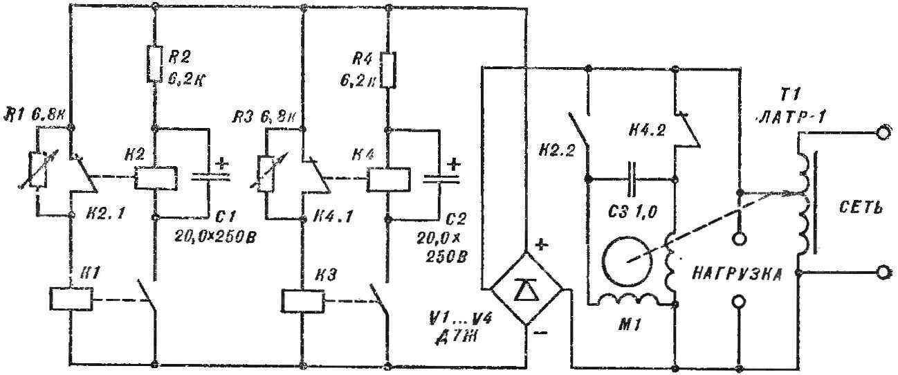
Voltage regulator (see Fig.) includes two trigger circuits, one of which is triggered when the decreasing voltage and the other at higher. The sensitive elements they serve as electromagnetic voltage relays K1, K3, with a clear threshold and release.
The Executive body for reversible motor with gearbox, the output shaft of which is connected via a tube section with the axis of the autotransformer. To its terminal Network connect lead wires and the terminals “Load” connected to inside network.
Resistors K1 and KZ are used for alignment voltage operate and release the relay K1, KZ, when you change the voltage on the windings is not more than 5%.
First, an automatic control unit, disabling the motor and the autotransformer. The circuit serves voltage of 220 V and turning the arrowhead voltage relay circuit, make it work. Relay K1 remains switched off.
Then increase the voltage to 230 V and .turn key pointer K1 make closed contact.
Relays K2 and K4 should be activated after 0.5—1 s after switching K1 and KZ. This time is settable chains R2С1 and R4С2.
Open the contact К2Л and K4.1 the power circuit of the relay coils K1, KZ are introduced of the resistors R1 and RZ. As a result, the voltage at K1, KZ decreases to the minimum value at which the relay held in on state. The exact adjustment is performed by adjusting variable resistors.
Then the voltage is reduced to the value of the funeral. While relays K1 and K2 must be switched off. This point is established by means of resistor M.
If the voltage is reduced to 210 V, must disconnect relays KZ and K4. The moment of triggering depends on the value of the resistor RS.
In conclusion, the automatic control device serves voltage of 220 V. Setting the pre-regulator of the autotransformer to the mark “220”, check the operation of the system as a whole. At higher voltage the motor slowly turns the knob of the autotransformer until then, until the voltage reaches the nominal value.
When the line voltage decreases, the motor rotates the shaft of the autotransformer in the opposite direction, increasing the output voltage.
Controller with high accuracy supports voltage ranging from 190 to 260 V at a load power of about 1.8 kW.
Vladimir GUREVICH, Kharkov


