The simplest electrical devices that our magazine offered to beginners work from a 3336L battery for a pocket flashlight. But it cannot provide much energy: after several hours of continuous operation, the battery “runs down”, and then it needs to be replaced.
It is much more convenient to power homemade devices from a constant source of electric current — a special device that takes energy from the lighting network. This is a step-down transformer. By plugging such a device into a household outlet, you can get any voltage you need: 4, 6, 8 or 12 volts (V).
What explains the wonderful properties of a transformer? The secret lies in the electric current itself. The 3336L battery serves as a source of direct current, that is, current that flows all the time, while the element is active, in the same direction. And in the household network, alternating current operates, changing the direction of its movement 50 times per second, or with a frequency of 50 hertz (Hz).
Alternating current is advantageously different from direct current in that it can be wonderfully transformed, that is, converted from current of relatively high voltage to current of lower voltage or vice versa.

The transformer device is simple. Two coils of insulated wire, called windings, are wound on a core. On diagrams, they are depicted the same way as inductance coils. The line between them denotes the core.
The action of a transformer is based on electromagnetic induction. Alternating current flowing through one of the windings creates a variable magnetic field around it and in the steel core. This field crosses the turns of the other transformer winding, inducing in it an alternating e.m.f. of the same frequency. If any load, for example an incandescent lamp, is connected to the terminals of this winding, alternating current will flow through the closed circuit.
The winding to which alternating current intended for transformation is supplied is called primary, and the one in which alternating current is induced is called secondary.
The voltage obtained at the terminals of the secondary winding depends on the ratio of turns of the primary and secondary windings. If the latter contains fewer turns than the primary, then its voltage is less than the voltage supplied to the primary. And, conversely, if the secondary winding contains more turns than the primary, then the voltage developed in it is greater than the voltage supplied to the primary winding.
At the same time, the power of the current P=UI, which can be obtained in the secondary winding circuit, never exceeds the power of the primary winding current. Therefore, by increasing the voltage, we lose in the magnitude of the current, and by gaining in the magnitude of the current, we lose in voltage.
Now independently make a step-down transformer for voltages of 4, 6, 8 and 12 V. A suitable core for it can be taken from some damaged transformer, calculate the number of turns that should be in the windings by the core, and then, having selected the wire, wind the windings.
Any power transformer is characterized by the maximum current power it can convert. This power is greater, the larger the cross-sectional area of the core S.
In transformers used to power radios, tape recorders, televisions, cores are usually assembled from W-shaped plates with bridges to them or wound from strips stamped from special, so-called electrical steel.
Calculate the transformer in this order. First, determine the cross-sectional area S of the core. To do this, multiply the thickness of the pack in centimeters by the width of the middle “tongue” of the plates (also in centimeters). Then calculate the number of turns W that should be per 1 V of voltage at a given core cross-section S, using the formula:
W = 50/S.
The number of turns of the primary winding depends on what voltage you have in your apartment: 220 or 127 V. If we want to reduce the voltage of 220 V, then the primary winding should have n1 = 220*W turns, and if it is 127 V, it will be enough to wind only 127*W turns of PEL wire 0.3—0.5 (for a 220-volt winding thinner, and for a 127-volt one — thicker).

Using a wooden mandrel (see figure), glue a frame from thick paper or pressboard to accommodate the windings. At its base, make a hole in the cheek and bring out the end of the wire about 20 cm long — the beginning of the coil.
Wind in one direction, laying turn to turn. Each layer is laid with cigarette paper or tracing paper. After the last turn of the winding is made, secure the wire with threads and bring it out through another hole in the cheek.
Apply a layer of insulating tape over the primary winding without gaps.
Make the secondary winding with PEL wire 1.0—1.5, winding it over the insulating tape. If you don’t have wire of this diameter, fold three PEL wires 0.3—0.5 together and wind with a “triple” wire.
Such a winding will give a voltage of about 12 V if you wind n2= 12*W turns. And what needs to be done to get 4, 6, 8 and 12 V using our transformer? It turns out that if you divide the turns of the secondary winding into parts, then, in addition to 12 V, you can also get lower voltages. To do this, first wind 4*W turns and fold the wire in half, making a tap 10 cm long. These turns make up a section of the secondary winding. At its terminals, when the transformer is connected to the network, the voltage will be 4 V.
Having made a tap from the first section, continue the work. Wind the second section in the same direction with 2*W turns. The beginning of the first section and the end of the second will give 6 V at the output. The next 2*W turns of the third section will increase the total voltage by another 2 V. And finally, having wound all the turns of the secondary winding, we get 12 V. Between them will be located the terminals of individual sections giving voltage 4, 6, and 8 V.
Don’t forget to clean the ends of the winding and section terminals from insulation.
Now work on the transformer core. Its plates are assembled “overlapping” until the frame window is completely filled and tightened with bolts or studs with nuts, having previously wrapped them with paper so that the plates do not short-circuit through the tightening bolts. A poorly tightened core will hum.
The transformer can only be tested after final assembly and always through a fuse. At the same time, you need to make sure that the winding terminals do not short-circuit with each other.
Let’s analyze such an example. Suppose we have a core made of Sh25 plates (W-shaped with a middle “tongue” width of 25 mm) with a plate pack thickness of 4 cm. So, the core cross-sectional area will be 2.5X4 = 10 cm2.
Let’s find out the number of turns that should be per 1 V of voltage for this core:
W = 50/S = 50/10 = 5 turns.
Now it’s easy to determine the number of turns in each winding. The network winding should have 5×220=1100 turns or 5X127=635 turns. For the secondary winding, you need to wind 5X12=60 turns, making taps from the 20th, 30th and 40th turns.
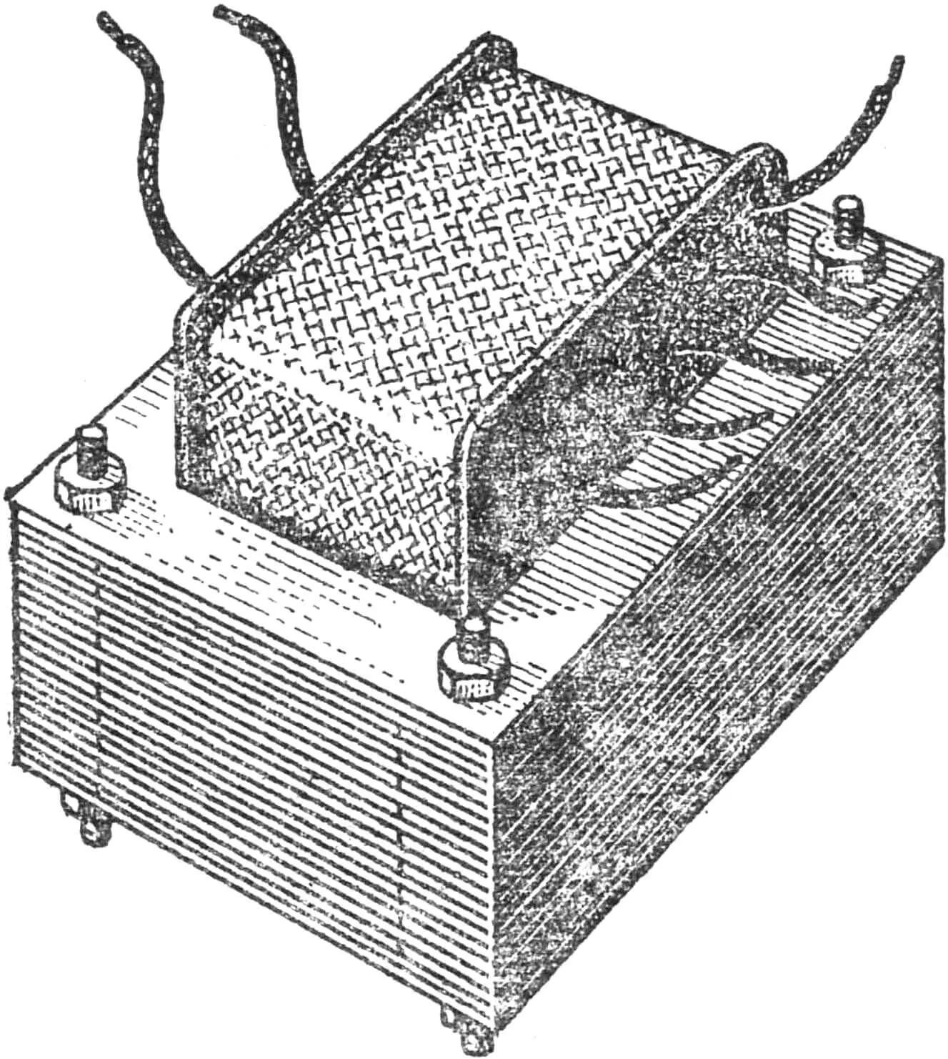
For the transformer, make a wooden box-case (it will protect the device from damage), install terminals on it, to which connect the secondary winding terminals.
Connect the primary winding to the network, and connect a homemade electric motor or a 6.3 V lamp to terminals 1—3.
A. VALENTINOV
Recommend to read
 LAMP FOR WORKSHOP
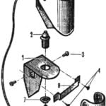
The lamp has only three pipe parts: the bracket, the clip and the visor. The first two (see picture) made of steel sheet with a thickness of 1-1,5 mm (dotted line marked bend line). The... BRISK, WHEEL, REVERSE
To the tinkerers, to engage in farming consider themselves not the first year. As a regular reader of "Modeller-designer", produced (with the help of coffee design) mower, mini moped...
