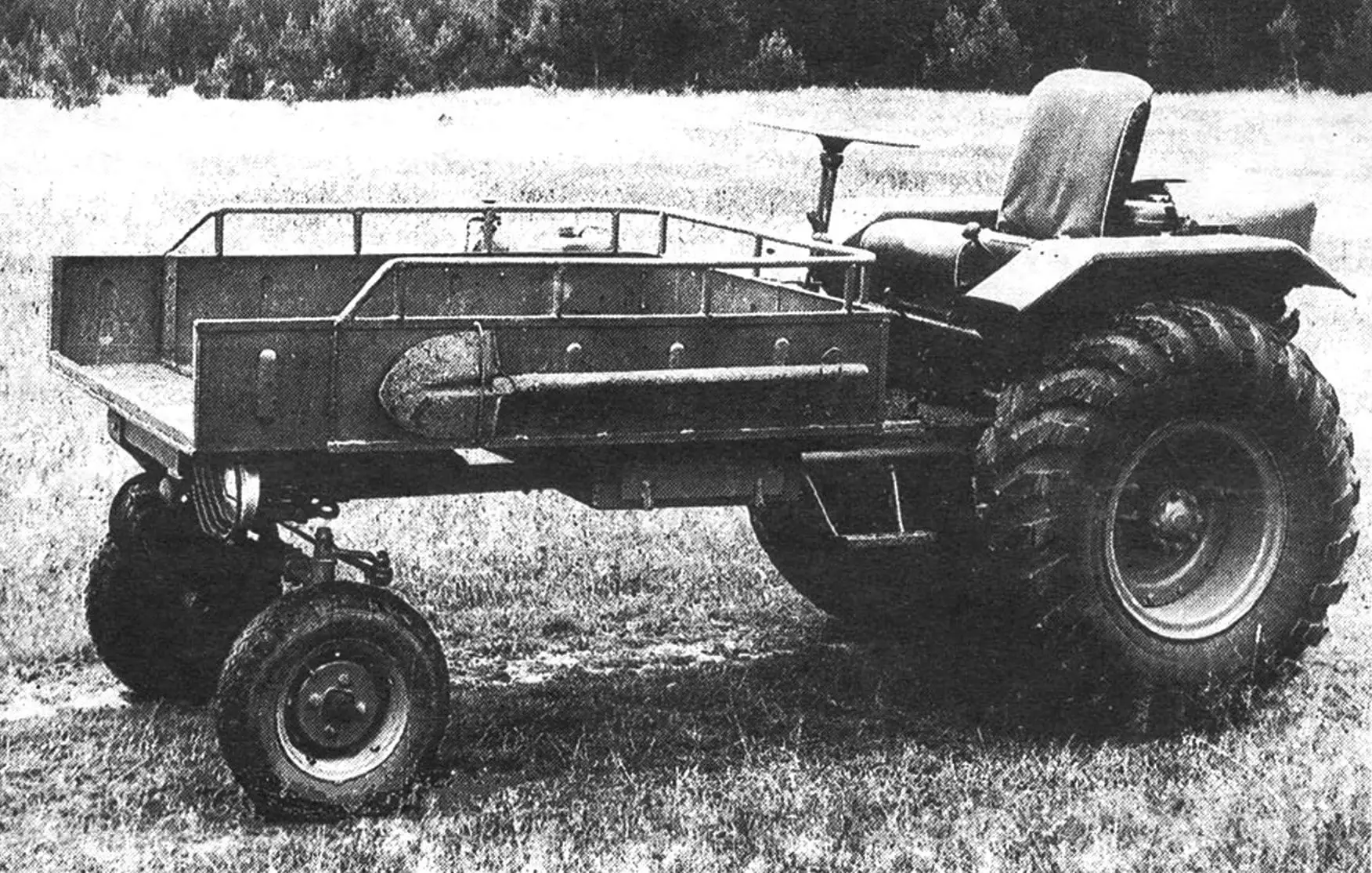
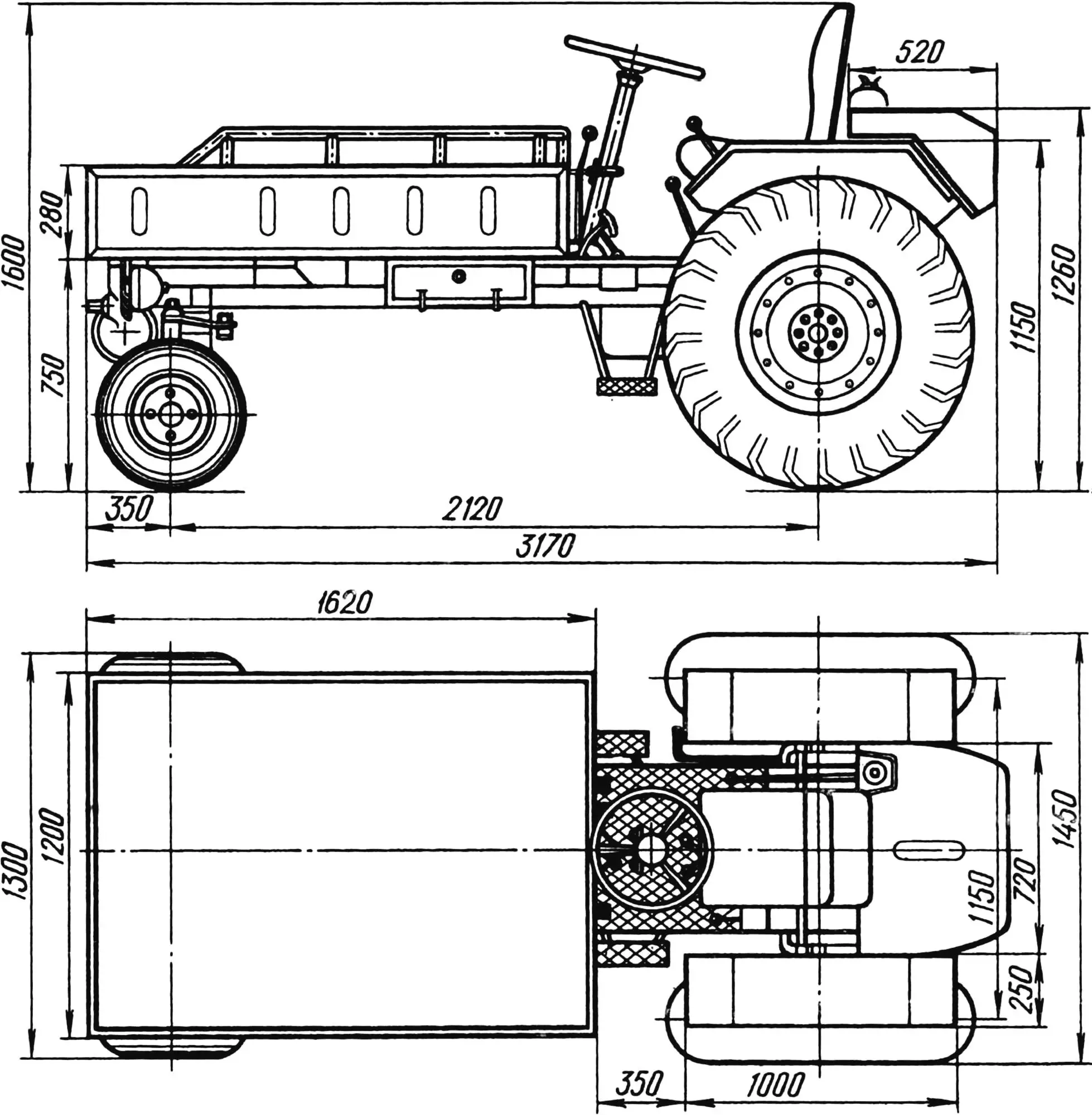
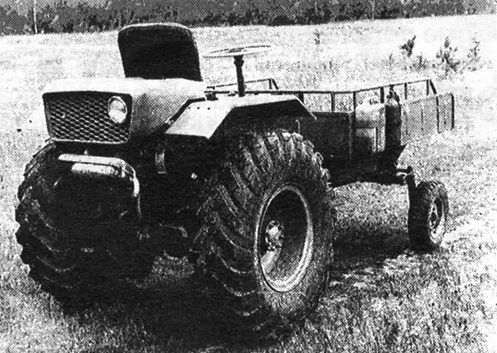
I built the self-propelled chassis called “Bychok” (Little Bull) more than ten years ago. Over this substantial period of use the machine has proved unpretentious, reliable and capable. Its layout is classic: cargo body at the front, driver’s station (in this case open) and engine at the rear; front axle steering, rear axle driven.
“Bychok” is intended mainly for carrying loads up to 500 kg at speeds up to 35 km/h. But it can also work the soil. You only need to replace the reverse reducer sprocket with a larger one before ploughing for higher tractive effort and hitch a plough. You can also use the power take-off shaft to drive a circular saw, water pump, mower, and the like.
The basis of the self-propelled chassis is a frame of fairly simple outline. It is welded from thick-walled round and square-section tubes. The many weld joints are reinforced with gussets and 4 mm steel plate overlays with lightening holes.
The frame is fitted with various brackets for the power unit, transmission and auxiliary equipment. The left frame console has an angled bracket to which the winch reducer is bolted (its cable drum is pulled by a bolt to a cross member). The front beam carries the front axle suspension unit, made from 25 mm steel plate and braced with struts. A channel bracket for the steering column is welded to the centre beam. Further along the side members are the transfer case mounting “feet”, longitudinal arcs of water pipe with angle brackets for the wings, a transverse arc with fuel tank frame studs, and plate (or channel) rear axle supports. Finally, welded to the rear beam are the reverse reducer platform and engine subframe, whose bearer is also attached at its front end to the transverse arc. Above is the bracket for the engine front mounting, resting on two ribs welded to the bearer. An octagonal plate ties the bracket to the transverse arc.
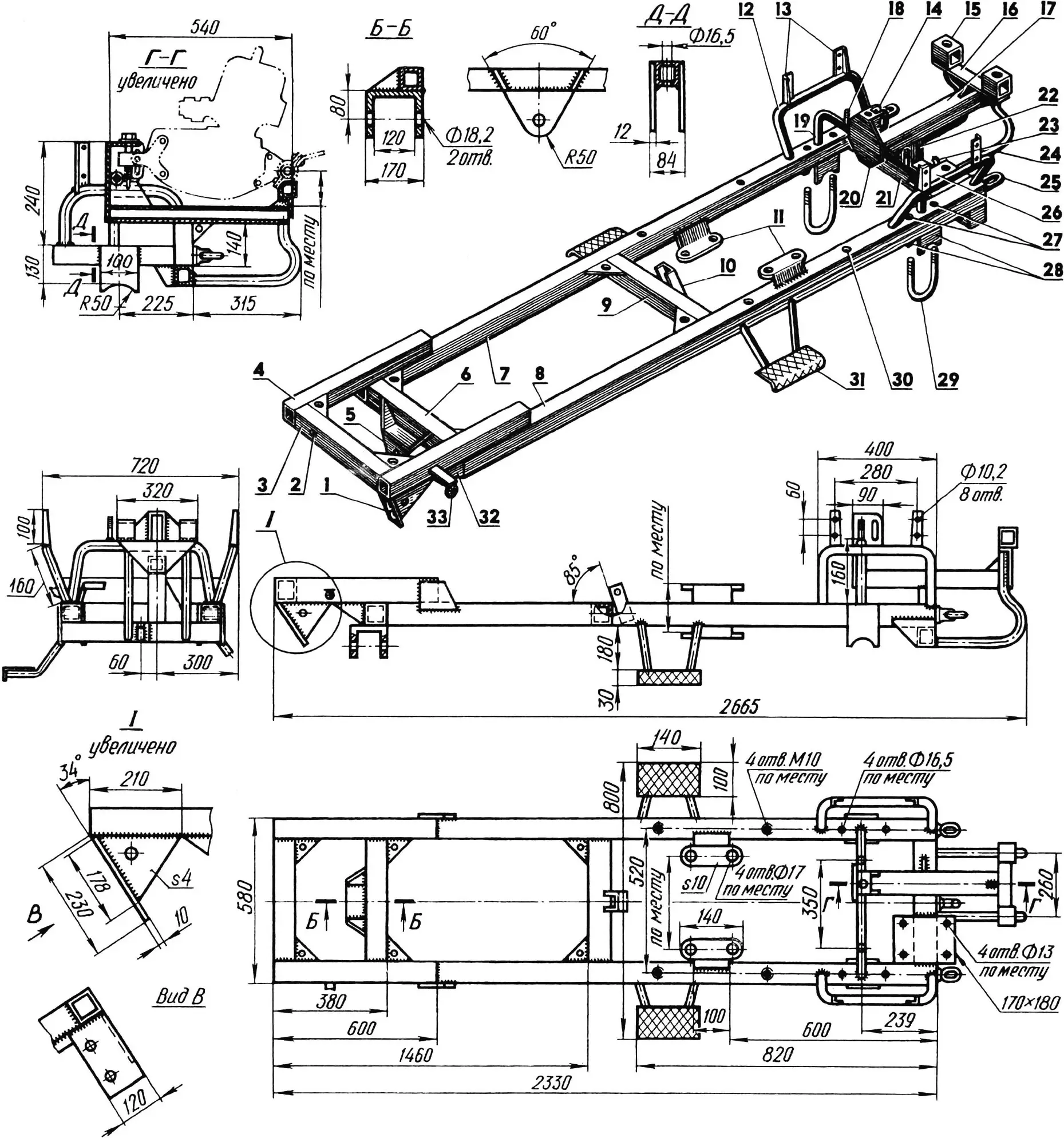
1 — winch reducer bracket (steel, 10 mm plate); 2 — winch drum mounting hole; 3 — cross member (60×60 tube); 4 — console (60×60 tube, 2 pcs.); 5 — front axle suspension unit; 6,9,21 — front, centre and rear beams (60×60 tube); 7,8 — side members (60×60 tube); 10 — steering column bracket (50×32 channel); 11 — transfer case mounting feet (steel, 10 mm plate); 12 — longitudinal arc (27 tube, 2 pcs.); 13 — wing mounting lugs (25×25 angle, 4 pcs.); 14 — engine bracket, front; 15 — spacer (60×60 tube, 2 pcs.); 16 — cross bar (90×56 angle); 17 — engine subframe bearer (60×60 tube); 18 — fuel tank frame M10 stud (2 pcs.); 19 — transverse arc (27 tube); 20 — engine subframe plate (steel, 4 mm plate); 22 — engine subframe upright (60×60 tube); 23 — tow hook; 24 — strut (27 tube, 2 pcs.); 25 — M22×1.5 eye bolt (2 pcs.); 26 — reverse reducer platform (steel, 10 mm plate); 27 — rear axle clamp holes, left; 28 — rear axle supports, left (steel, 12 mm plate); 29 — M16 clamp, left; 30 — driver platform M10 mounting holes (4 pcs.); 31 — left footrest; 32 — gusset (steel, 4 mm plate); 33 — headlamp bracket.
The other end of the engine subframe bearer carries an angle cross bar stiffened by a vertical rib, with two square-tube spacers on which the engine rests by its rear mountings. The cross bar and rear beam are also connected by two water-pipe struts (besides stiffening the subframe they serve for stowing the tow rope when not in use).
The side members also carry the driver platform with pedals and control levers and the cargo body. More on that later.
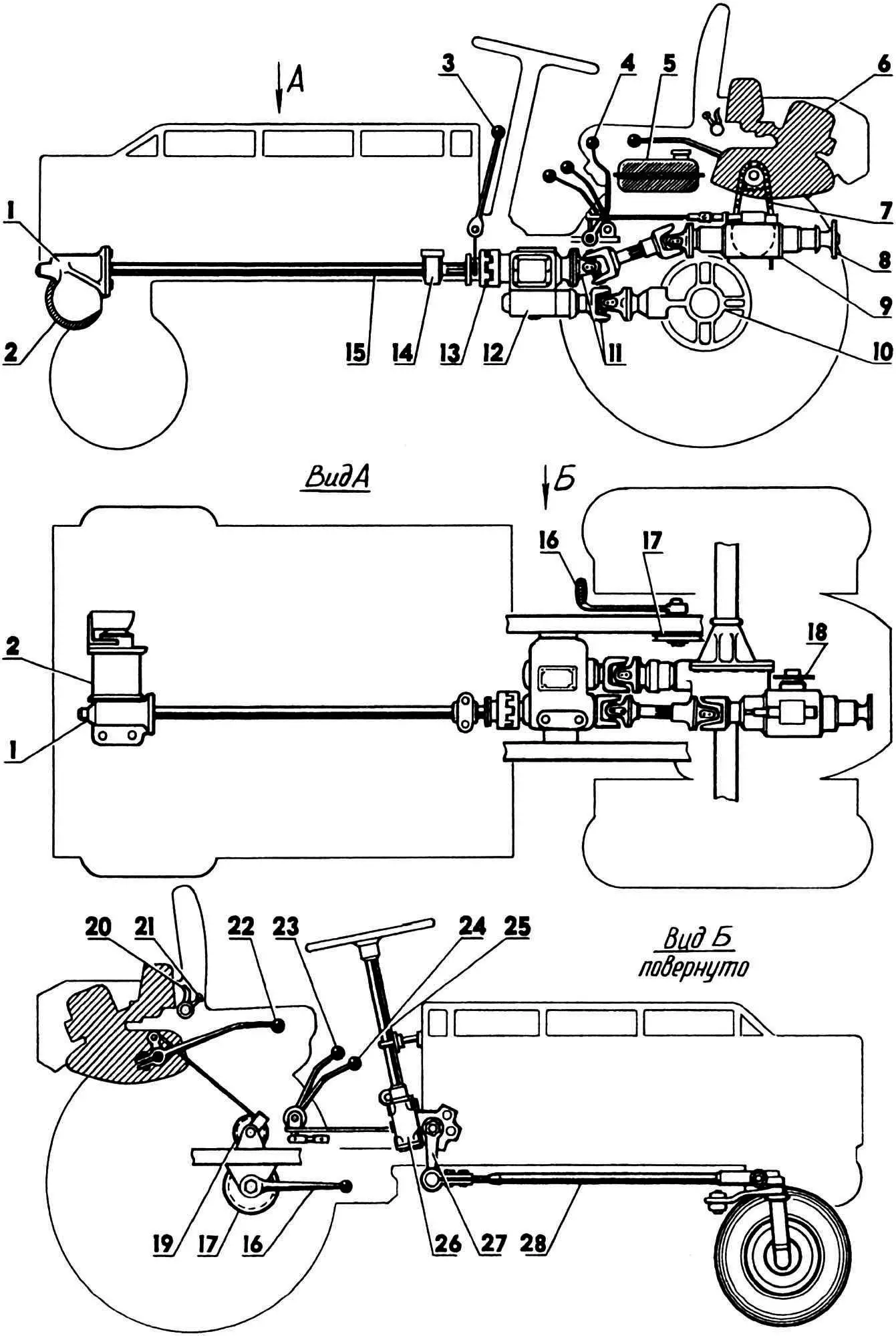
1 — winch; 2 — cable drum; 3 — winch engagement lever; 4 — reverse lever; 5 — fuel tank; 6 — engine; 7 — chain drive; 8 — reverse reducer power take-off shaft; 9 — reverse reducer; 10 — rear axle; 11 — propeller shafts; 12 — transfer case; 13 — dog clutch; 14 — bearing support; 15 — winch drive shaft; 16 — engine start lever; 17 — cable engine start block; 18 — reverse reducer drive sprocket; 19 — intermediate block; 20 — decompressor lever; 21 — fuel corrector lever; 22 — gearbox lever; 23 — rear axle disconnect lever; 24 — transfer case lever; 25 — steering column; 26 — steering gear; 27 — steering arm; 28 — longitudinal steering link.
The “Bychok” engine is an IZH-P-3 (from the S3D invalid carriage). Its 14 hp proved sufficient. I was tempted to keep battery ignition and electric starter, but with them the engine did not fit between the wings. So the bulky G-108M generator and ST-351-B starter were removed. The motor immediately became noticeably lighter in both weight and size. The voltage regulator, battery and extra wiring were no longer needed. Instead I fitted a G-421 generator with contact ignition from a “Minsk” motorcycle, which powers the lights. The ignition coil is from an IZH-PS-350 motorcycle.
The IZH-P-3 sits on the engine subframe welded to the chassis frame. The front engine mounting bracket is a box with the same chain tensioner as on the S3D. The silencer is also bolted to the rear engine mounting clamps.
The engine is started by a foot lever whose bracket is welded to the chassis frame on the right. On the lever pivot there is a block holding one end of a 5 mm cable. The other end, over an extra guide pulley, is attached by a special clamp to the engine kickstarter lever. After starting, the foot lever is raised by hand and held by a spring hook so it does not swing when driving.
For gear changes a fairly long tubular lever on the engine gearbox output shaft is placed between the driver’s seat and the right wing.
Torque from the engine output sprocket is transmitted by chain to the reverse reducer drive sprocket. Thanks to the reducer, “Bychok” can move in reverse at the same speeds as forward. The reverse reducer ratio is 1:1.2. It is home-made, though some gears and shafts from a “Belarus” tractor transmission are used.
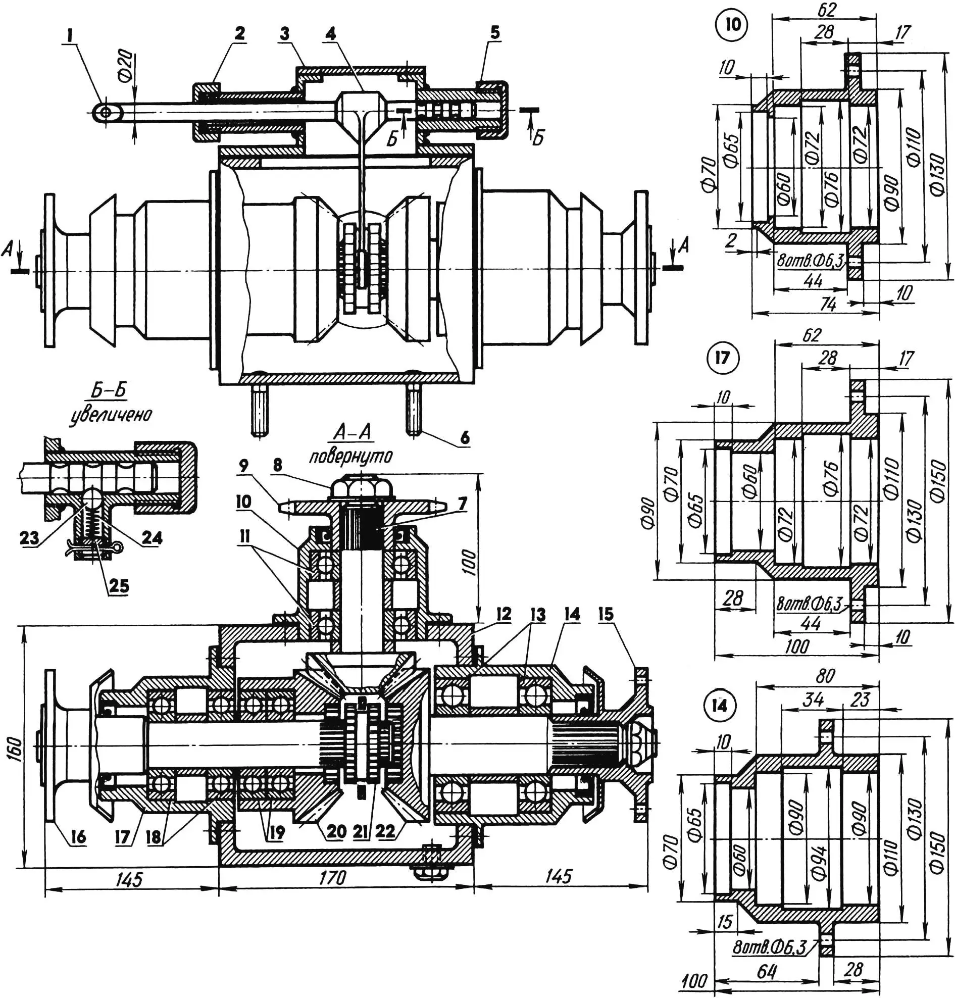
1 — clutch rod; 2 — shaped nut; 3 — clutch cover; 4 — clutch fork; 5 — shaped plug; 6 — reverse reducer M12×1.5 stud (4 pcs.); 7 — reverse reducer drive gear shaft tail; 8 — M20×1.5 nut; 9 — reverse reducer drive sprocket; 10,14,17 — bearing housings; 11,18,19 — 207 bearings; 12 — reverse reducer housing (steel, 8 mm plate); 13 — 308 bearings; 15 — power take-off shaft flange; 16 — transfer case drive shaft flange; 20 — transfer case drive shaft gear; 21 — clutch; 22 — power take-off shaft gear; 23 — detent ball; 24 — detent spring; 25 — adjusting screw.
The reverse reducer housing is welded as a box from five 8 mm steel plates. Three side faces have windows into which bearing housings of steel 30 with shafts are fitted. The rear shaft is driven (power take-off), in constant mesh and turns one way. The front shaft is also driven. Via a modified GAZ-51 cardan it delivers torque to the transfer case. The rotation of this shaft can be reversed by a clutch on the reverse reducer housing cover (the cover is held by eight M8 screws). So the clutch fork has three fixed positions: forward — centre (“neutral”) — rear. The clutch is operated by a lever on the driver platform between the left wing and seat.
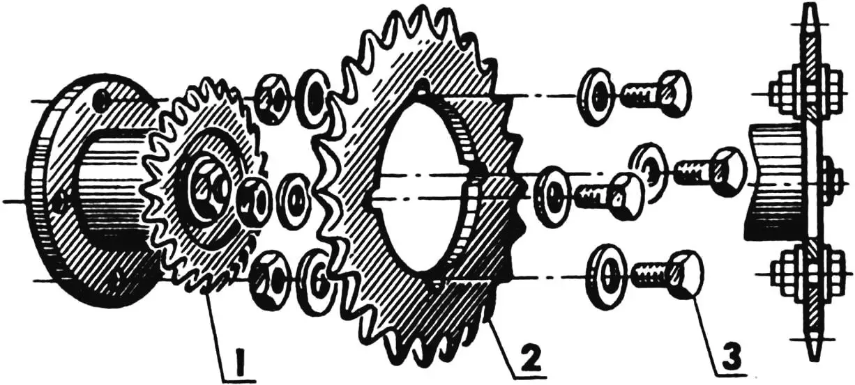
1 — reverse reducer sprocket (z = 20); 2 — gear ring (z = 42); 3 — M10×1.5 bolt with nuts and washers (4 sets).
The reverse reducer is mounted between the engine and rear axle. With four M12×1.5 studs in its base and four rubber mounts it is fixed to a dedicated platform on the “Bychok” frame rear beam.
It was said above that for ploughing the reverse reducer sprocket must be replaced. Strictly speaking on “Bychok” it is not replaced but augmented with a new gear ring cut from a larger sprocket (z = 42). This ring is held by four M10×1.5 bolts. In that case a longer chain is used (also from the S3D invalid carriage).
I agree it is not the ideal solution, though in my view it is original. As this change is rarely needed, it is acceptable.
The transfer case is from a GAZ-66 truck and was not modified. It receives torque from the reverse reducer and delivers it to the winch (forward) and rear axle (rear). It is mounted on special 10 mm “feet” welded to the frame side members. Fixing is by four M16×1.5 bolts with rubber mounts.
The transfer case allows switching between low and high range without using the engine gearbox, giving the gearbox an easier life and longer durability.
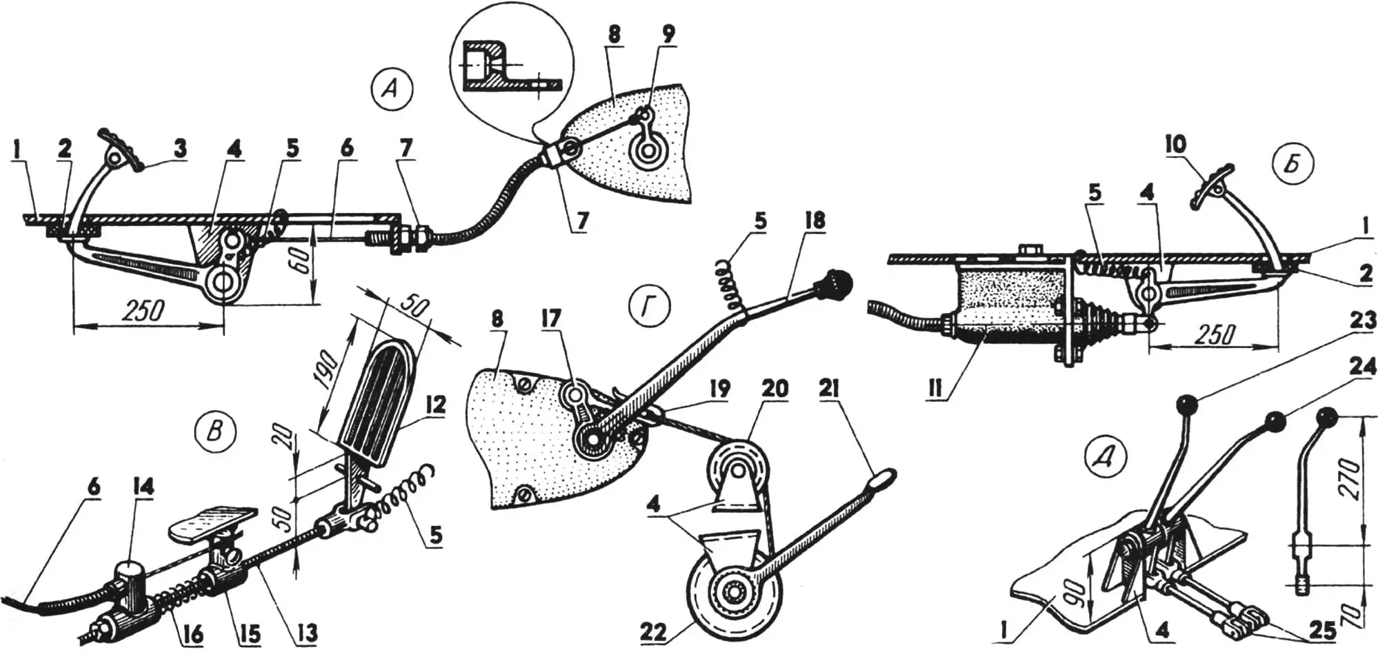
A — clutch; B — brake; C — throttle; D — gearbox; E — rear axle and transfer case;
1 — driver platform; 2 — rubber washers; 3 — clutch pedal; 4 — mounting brackets; 5 — tension springs; 6 — cables; 7 — cable outer stops; 8 — engine covers; 9 — clutch lever; 10 — brake pedal; 11 — brake master cylinder; 12 — throttle pedal; 13 — rod; 14 — slider; 15 — rod guide; 16 — compression spring; 17 — kickstarter lever; 18 — gear lever; 19 — cable clamp; 20 — guide pulley; 21 — engine start lever; 22 — block; 23 — transfer case lever; 24 — rear axle disconnect lever; 25 — adjustable rods.
The transfer case is operated by two levers on the driver platform under the seat. The first disconnects the rear axle, the second selects low or high range (via “neutral”). With the lever in neutral, the reverse reducer power take-off or winch can be used.
The transfer case is connected to the rear axle final drive by a short propeller shaft, and to the winch by a dog clutch. The sliding half-clutch on the winch drive shaft splines is operated by a lever in front and left of the steering column reducer. The winch drum has no freewheel; its rotation direction is changed by shifting the reverse reducer. The winch drive shaft splined portion is supported by a bearing whose housing is bolted to the frame.
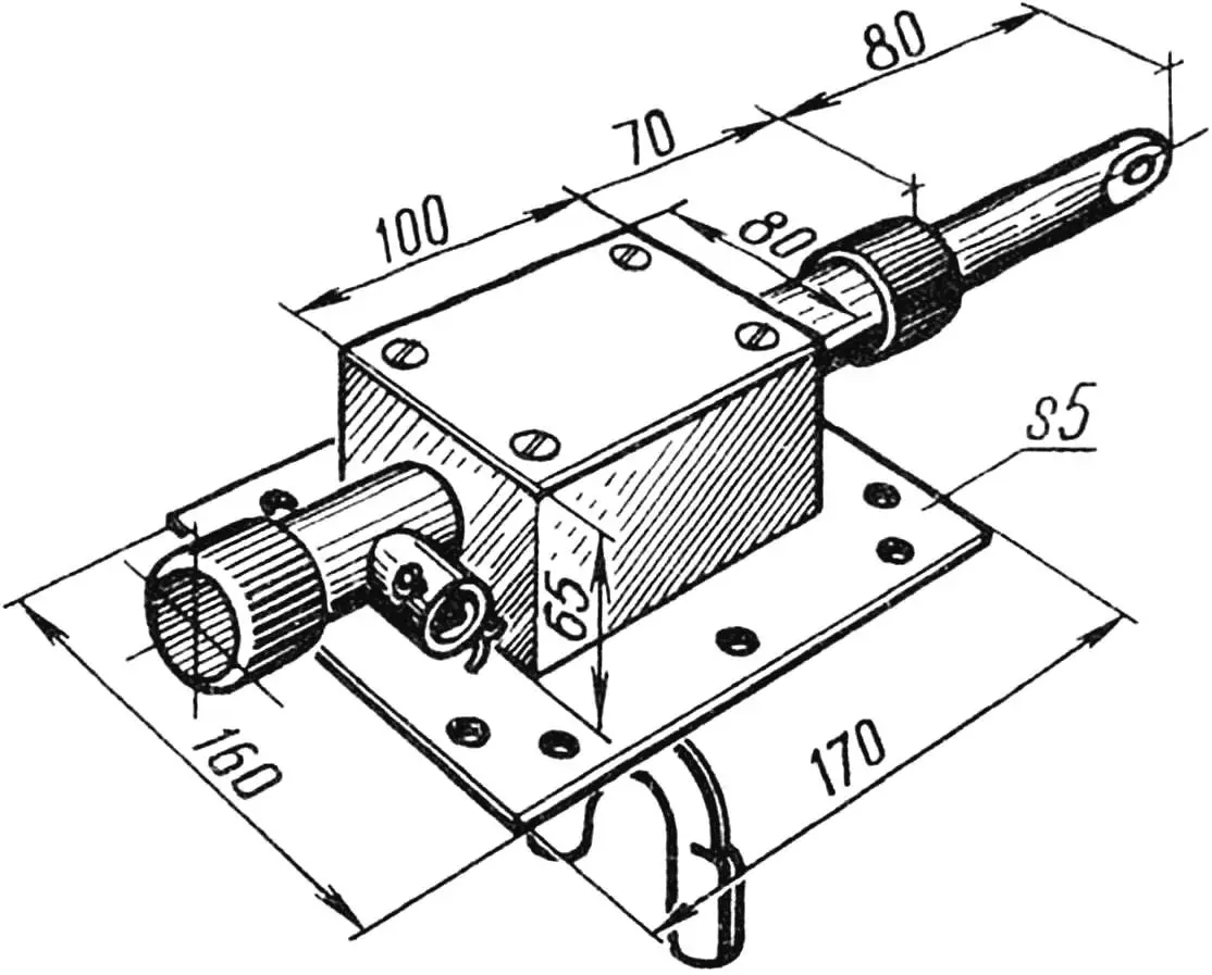
The winch reducer is a heavy worm unit from the steering column of an old tractor of unknown make. The drum is made from tube and carries 10 mm diameter cable 15 m long. The winch is fixed to the “Bychok” frame bracket by three M14 bolts.
The steering column is from a GAZ-51 truck. When fitted it is rotated 180° about its vertical axis so the reducer output shaft is on the right. The column is fixed to the frame bracket by five M10 bolts.
The longitudinal steering link and some other steering parts are also from a GAZ-51. The transverse link and steering arms are from the S3D. Pivot and steering axes are lubricated through grease nipples.
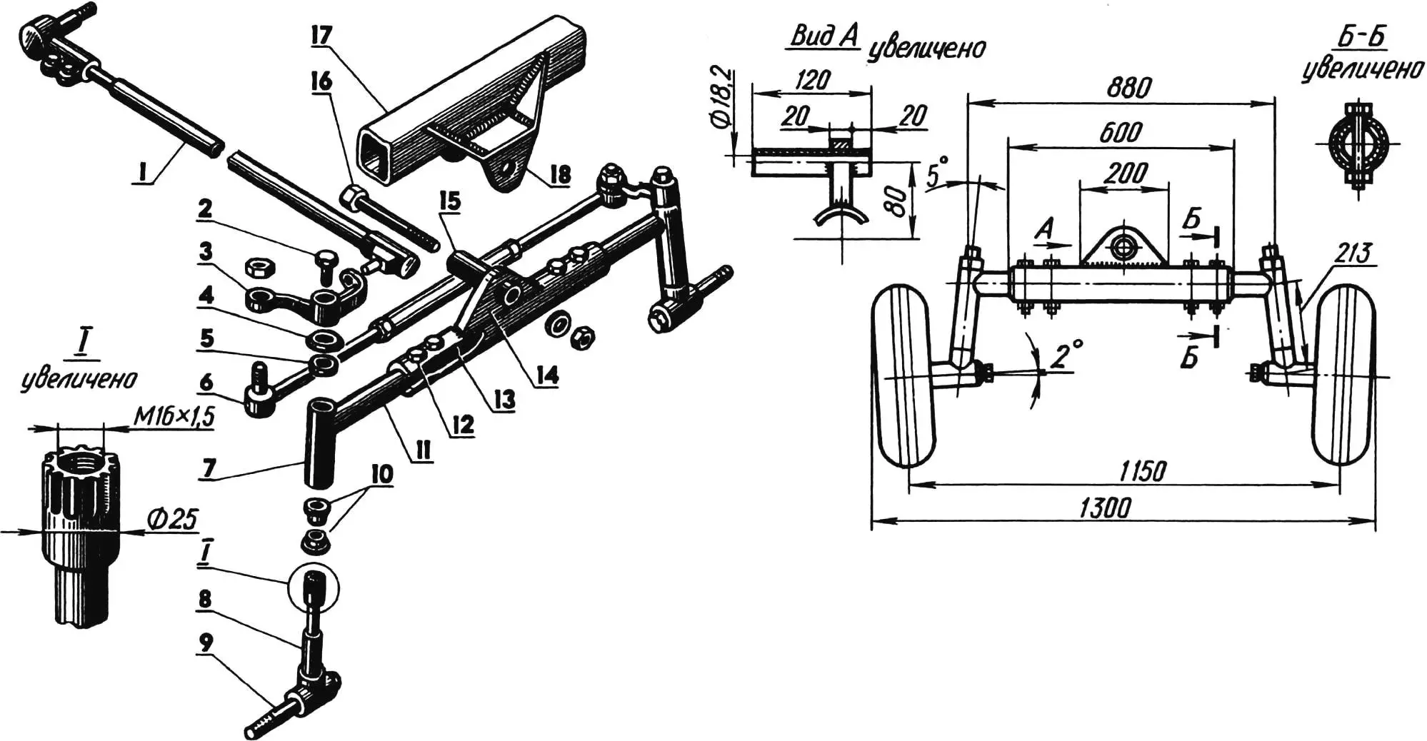
1 — longitudinal steering link; 2 — M16×1.5 bolt; 3 — right steering arm; 4 — cupped washer; 5 — felt seal; 6 — transverse steering link; 7 — kingpin bush (42×32 tube); 8 — kingpin; 9 — half-shaft; 10 — bearing bushes (bronze, Ø32×25); 11 — console (50×5 tube); 12 — M12 bolt; 13 — beam (60×5 tube); 14 — stiffening rib; 15 — spacer bush (30×5.9 tube); 16 — M18 bolt; 17 — self-propelled chassis frame beam; 18 — front axle suspension unit.
The front axle is welded from tubes of different diameter. For strength the side tubes (consoles) telescope into the centre beam and are fixed by M12 bolts. A 25 mm steel plate stiffening rib with a spacer bush for the pivot bolt is welded to the beam centre.
Steering arm loads are passed to the kingpins via splined joints. As the kingpins only turn through a limited angle, plain brass bushes are enough. The front wheel half-shafts are welded directly to the kingpins. The wheels are from the S3D invalid carriage. They have no brakes.
The rear axle is from a GAZ-51 truck, shortened. Its length between half-shaft flanges is now 1220 mm. The axle tubes sit in the chassis frame supports and are clamped from below by two 16 mm U-bolts through the side members. Rear wheels are from a ZIL-157 truck. When mounted on the hubs they are oriented so the hubs do not extend beyond the wheel width.
The “Bychok” brake system is hydraulic, from a GAZ-51, and acts only on the rear wheels.
The driver platform with control levers and pedals is made from 4 mm chequered steel plate. It has two cutouts: one for the brake master cylinder, one for the transfer case mounting “foot”. At the rear, brackets carry the reverse reducer, transfer case and rear axle disconnect levers. Two lugs for the fuel tank frame are also welded there. At the front, in the usual layout, are the clutch, brake and throttle pedals. Pedal brackets are under the platform. The platform is fixed to the frame by four M10 bolts on rubber pads.
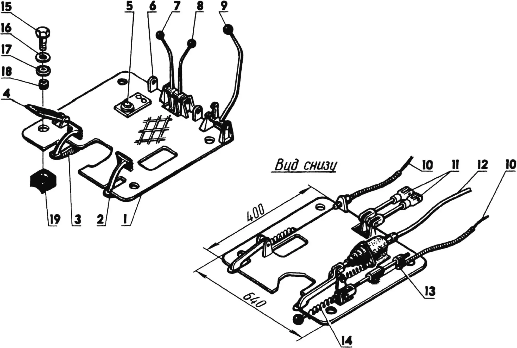
1 — floor (chequered steel, 4 mm plate); 2 — clutch pedal; 3 — brake pedal; 4 — throttle pedal; 5 — brake master cylinder; 6 — fuel tank mounting lug (2 pcs.); 7 — rear axle disconnect lever; 8 — transfer case lever; 9 — reverse lever; 10 — control cables in sheaths; 11 — adjustable rods; 12 — brake system pipe; 13 — throttle pedal slider; 14 — spring; 15 — platform-to-frame M10 screw (4 pcs.); 16 — steel washer; 17 — rubber washer; 18 — rubber bush; 19 — rubber pad.
The chassis wings are from a DT-20 tractor. They matched well in size and are relatively light. They are fixed by eight M10 bolts (to lugs on longitudinal arcs welded to the side members).
The wings are not only mudguards. They carry the driver’s weight because the seat rests on them — its rear tube locates in sockets made from 25×20 mm section tube. On the left wing are the electrical panel and tool box; on the right, the engine air cleaner (from an IZH-PS-350 motorcycle) and a height-adjustable bracket with decompressor and fuel corrector levers.
The driver’s seat is from the S3D invalid carriage, slightly modified and reinforced. It can be adjusted vertically and horizontally and hinged forward so the back rests on the steering wheel for easy fuel tank access.
The fuel tank is also from the S3D. It is mounted under the seat on a frame welded from 27 mm diameter tubes. As the tank is below the carburettor float chamber, a “Veterok” outboard fuel bulb is fitted in the fuel line.
Fuel filtration is taken seriously. The tank filler has a primary filter — a removable fine mesh. Then via a KR-12 tap, its mesh and sediment bowl, fuel flows through flexible rubber hoses to the bulb, then to a sediment filter, to the fuel pump (which has its own filters) and only then to the carburettor. It is a bit involved but operation has justified it.
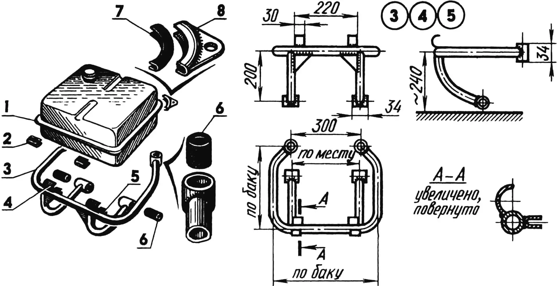
1 — fuel tank; 2,7 — rubber pads (4 pcs.); 3 — fuel tank frame; 4 — seat tube arc holder (2 pcs.); 5 — strap (2 pcs.); 6 — rubber bushes (4 pcs.); 8 — fuel tank holder (2 pcs.).
The fuel tank frame has four mounting points: two lower (with rubber bushes) are bolted by M10 to the driver platform lugs, and two upper (also with rubber bushes) go on studs on the chassis transverse arc.
The fuel tank is also fixed at four points (with rubber pads): at the front by straps welded to its frame, at the rear by the same studs on the transverse arc. The many rubber pads absorb engine noise and vibration.
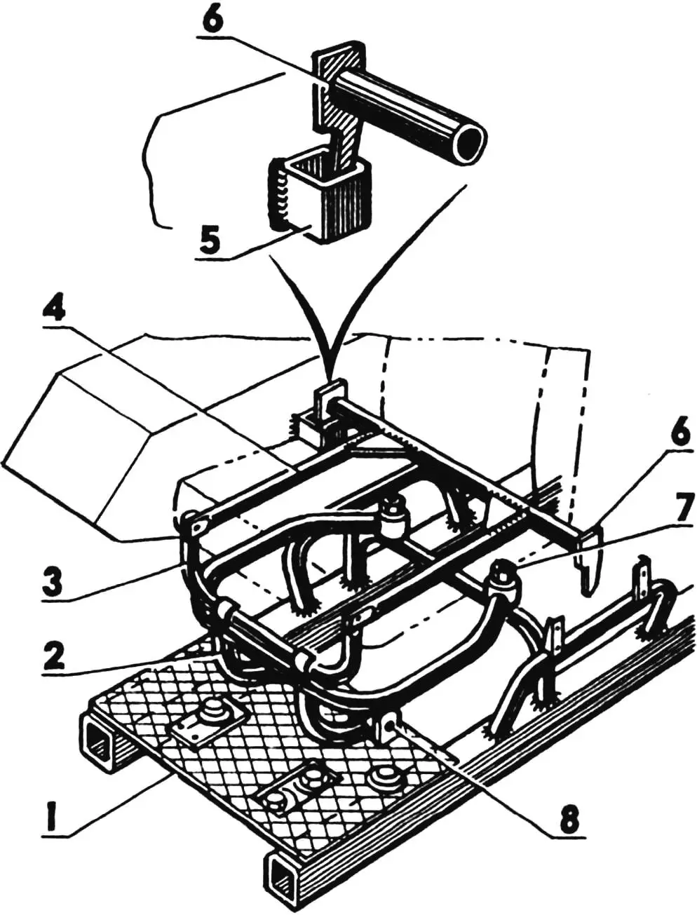
1 — driver platform; 2 — fuel tank frame; 3 — seat tube arc; 4 — seat base; 5 — seat base wing locating lug; 6 — seat base locating teeth; 7,8 — fuel tank frame mounting points.
The engine is covered from above by a 1.8 mm steel bonnet with a rear ventilation grille and headlamp from a “Riga” moped. The bonnet opens forward and is held by a prop. When closed it rests on two rubber pads on the wings and is held by two coil springs.
Under the body at the front left, “Bychok” has a headlamp from the S3D, adjustable vertically and horizontally. The electrical system is very simple. The switch panel has a main switch and dip/main beam for the front lamp; the rear one (from the “Riga” moped) only comes on when reversing.
The cargo body is welded from 1.8 mm steel plate and edged with 20×20 mm angle. For stiffness the sides have pressed vertical beads and a top rail of 21 mm diameter tubes. The front side drops and is held by a hook on a chain. With the side down and flush with the floor you get a longer deck for oversized loads. A spade is fixed to the left side, a fuel can and fire extinguisher to the right. Under the body floor on both sides are roomy metal lockers.
The body is mounted as follows. First four wooden bearers (board and batten, hot linseed soaked) are bolted to the frame with U-bolts and bolts. The body itself is then fixed to them by M8 round-head bolts.
In offering this description to the magazine I had this in mind. All amateur builders, when making their machine, draw on the experience of others. Perhaps my work will be of use to someone too.
«Modelist-Konstruktor» No. 9’99, V. PETROV
Recommend to read
 OVERCHARGING THE BATTERY? Is ELIMINATED!
One of the problems for the citizens-owners of vehicles is the condition of the batteries. Frequent stops on subsequent runs of the engine discharged battery, a full charge from an... AND THAT UNDER THE ROOF?
When early man left the caves and moved into the valleys and forests, the primitive housing steel construction with roof canopy, constructed from branches and animal skins. Centuries...
