
 …GRINDING
 Cutter lathe went through a rough raw preset. Turner stopped the lathe, measured the diameter and adding a couple of “dozen”, again ran clean. Another measurement: all right.
But Turner is in no hurry to remove the item from the holder. He pulls out some tables tool, fixes it in the tool post and again presses the “start” button. Included creep, and unusual tool is moved along the workpiece, leaving an almost mirror surface.
This operation is called a run. The tool is hardened ball, which is pressed against the workpiece with a mandrel. In addition to the greater cleanliness of the surface, rolling, hardens the surface layer of metal: ball, deforming the surface layer of the workpiece, negative it.
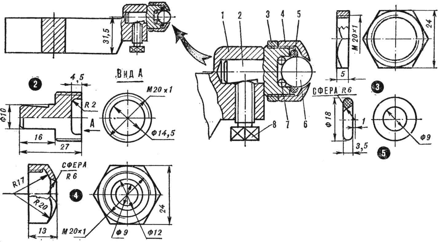
Fig. 1. Device for running parts on the lathe:
1 — holder, 2 — body, 3 — nut, 4 — clip, 5 — malinowy oil seal, 6 — working bulb Ø 12 mm, 7 — bearing balls Ø 4 mm 8 — screw retainer.
To make such a tool is not too difficult even in the school workshop. Figure 1 shows the Assembly drawing and detailing tools. It consists of a holder (its dimensions match the toolholder flock 1А62) with locking screw and the housing, wherein the fixed working tool — steel ball Ø 12 mm. It rotates in a kind of bearing of eight chetyrehkilometrovoy balls. The body under working ball should be cement with the subsequent hardening.
…AND SLOTTING MACHINE
Not every workshop, school, or kutowski Sutovsky — there is a slotting machine, and the necessity for it exists almost always. Pulleys, sprockets, gears fixed to shafts using keys, which in these parts is required to perform a keyway. And then it will be able to help out a lathe.
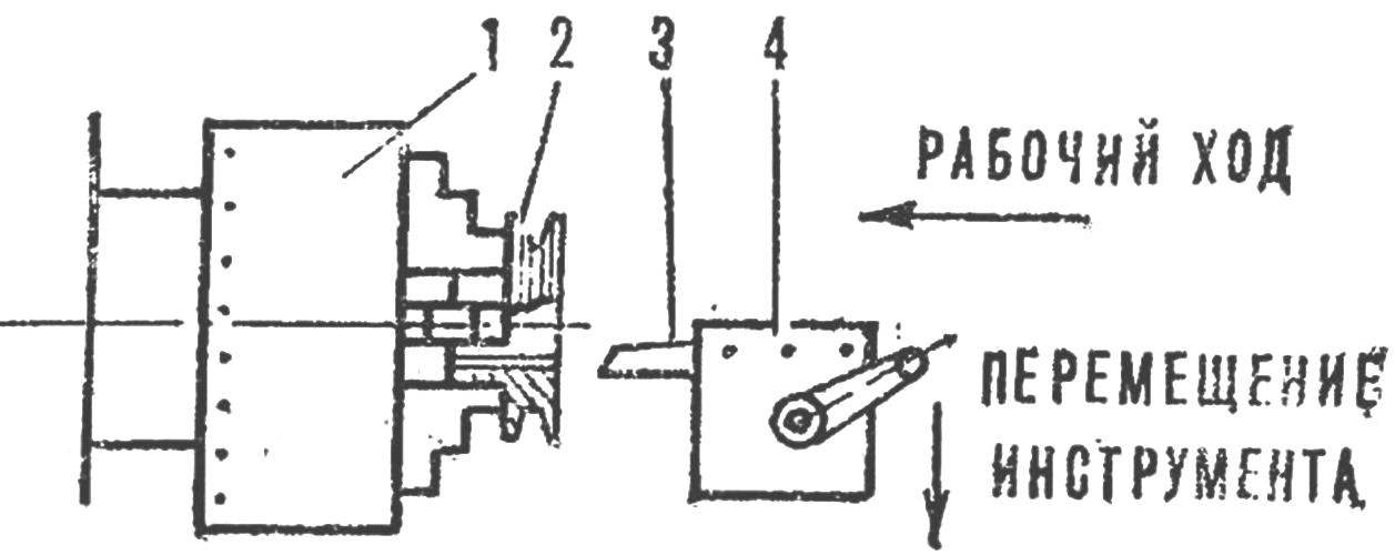
Fig. 2. Lathe in the role of slotting:
1 — Chuck lathe machine, 2 — work piece (e.g., pulley), 3 — cutter, 4 — gang plate.
To do this, the toolholder of the machine tool is clamped in a special way sharpened the cutter width must match the width of the pins. Tie up the cartridge, with handwheel longitudinal feed, remove the first chips. Then the cutter is shifted by handwheel cross feed of the cross slide and the operation is repeated. The whole cycle of processing of key grooves is not more than three to five minutes depending on the workpiece material.
…AND BESIDES…
lathe — the dividing head. One has only to divide the circumference of the cartridge for a certain number of parts (for example, a 24 — since this number is a multiple of 2, 3, 4; 6, 8 and 12), apply in locations dividing point core – and you will be able to mark workpieces without having to remove them after turning off the machine.
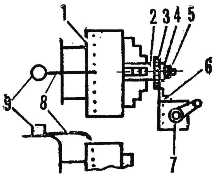
Fig. 3. Chuck lathe — dividing head:
1 — cartridge, 2 — bar, 3 — subject to the layout detail, 4 — puck, 5 — Ganka, 6 — cutter-Scriber, 7 — tool holder, 8 — needle, 9 — weight.
Actually the markup is sharpened cutter. To do this, to combine the desired point of the core of the arrow-pointer, to bring the details of the cutter and draw a detail risk turning the handwheel longitudinal or cross feed.
