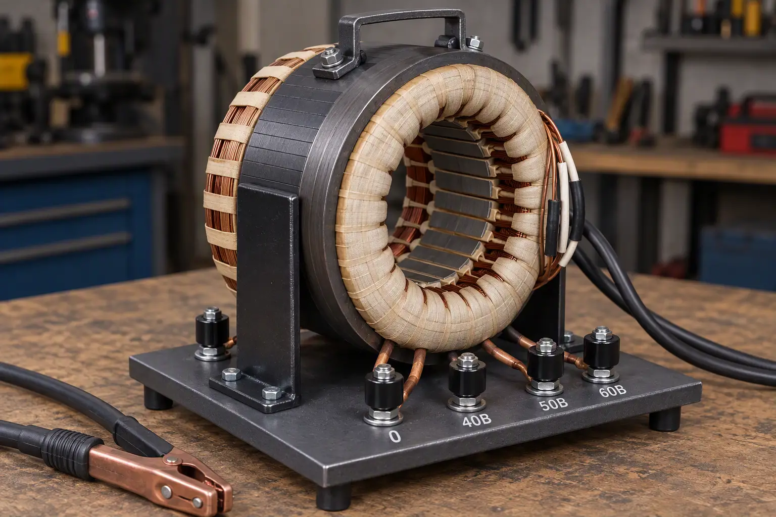
For those who have not yet acquired a welding machine (WM), I recommend making one yourself based on a failed asynchronous electric motor. The costs are minimal, and as for the result… And there are quite a few designs that can be used to turn a scrap stator into a solid welder (see, for example, “Modelist-Konstruktor” No.8’92, 11’95, 1’96, 3’96). I will be glad if my tips, proven in practice, are also of use to someone.
While experimenting with various welding machines, I became convinced that the chase for a powerful unit (typical, as a rule, of beginners) is far from always economically justified. For most jobs at home, a welder made from the stator of an asynchronous electric motor with a power of 1—1.5 kW and a magnetic core with a cross section of 40 cm2 will do quite well. For connection to a 220 V household mains with welding voltages of 40, 50 and 60 V delivered to the arc, the primary winding of such a WM should have 220 turns, and the secondary — 60, with taps from the 40th and 50th “bus” turns.
Once the stator is in your hands, do not rush to chop off or burn out the winding. In most cases it is quite suitable as starting material for the “high-ampere buses” that the WM needs.
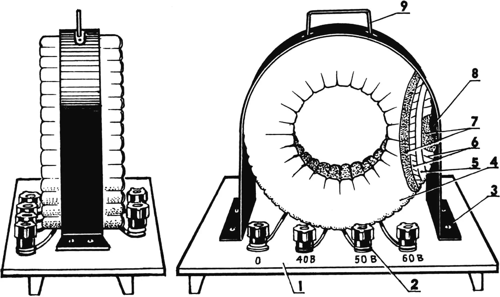
1 — electrically insulating base; 2 — terminal (6 pcs.); 3 — clamp; 4 — secondary winding (60 turns of a thickened bus — a bundle of 9 — 15 PEV2 wires with a total copper conductor cross section of 30 — 35 mm2, wrapped with fabric-backed insulating tape, taps from the 40th and 50th turns); 5 — interlayer insulation (2 layers of linen or cotton fabric with subsequent impregnation with bakelite varnish); 6 — primary winding (220 turns of a bus — a bundle of 3 — 6 PEV2 wires with a total copper conductor cross section of 6—8 mm2, wrapped with fabric-backed insulating tape); 7 — reinforced insulation (made as in item 5, but with twice as many insulating layers); 8 — toroidal magnetic core; 9 — handle.
In most asynchronous motors, the stator winding consists of several overlapping sections. Each of them is laid in the corresponding slots of the magnetic core. After carefully inspecting the stator, determine which section was laid last. Start the dismantling from that one.
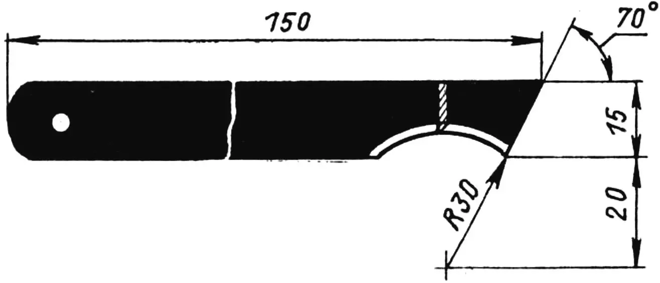
First of all, try to knock out the wedges (usually wooden) that secure the winding turns in the slots. If this cannot be done with improvised means, use a tool in the form of a knife of a special shape, made from a hacksaw blade for a metalwork fretsaw.
The technique here is simple. Moving the knife toward yourself, shave chips from the wedge until it breaks into pieces. After removing the resulting fragments, start extracting the section itself from the slots turn by turn. Do this carefully and without hurry, in the reverse order of the factory winding. After freeing the last section, unwind the wires and straighten them, obtaining lengths from 20 to 30 m. From these, compose the buses of the required cross section.
Thus, to obtain the bus for the primary (mains) winding of the WM, you need to put together 3—6 wire blanks so that the total copper conductor cross section is 6—8 mm2. The resulting bundle should be wrapped along its entire length with fabric-backed insulating tape. Long insulating strips sewn (or glued) from scraps of linen or cotton fabric are also quite acceptable. Even paper tape cut, for example, from mail or cement bags will do.
To make the work of fabricating an insulated bus go smoothly, tie the original bundle of wires in several places with twine and coil it into a reel 600—800 mm in diameter. Apply the tape itself at an angle to the bundle so that each subsequent turn overlaps half of the previous one and the insulation becomes two-layered. When using fabric or paper, remember that these materials need subsequent impregnation with bakelite varnish or some paint (except water-emulsion paint).
In the same way, make the bus for the secondary winding of the welding transformer. Only the number of wires in it should be such that the total copper conductor cross section equals 30—35 mm2.
Now about reworking the magnetic core. The essence of this is to remove the bridges between the sections of the base stator using a hammer and chisel. Then smooth the sharp edges formed in the process with a file. The finished magnetic core is coated with several layers of insulation using the technology described above.
To make winding easier, insert the wire into the core and rotate the entire ring until the last turn sits freely on the toroidal core of the welder. You will get, as it were, two interconnected links of a heterogeneous chain (a steel magnetic core and a copper coil).
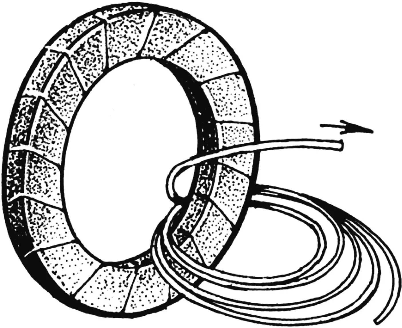
It is better to wind the transformer buses as a two-person job. First clamp the edge of the magnetic core in a vise, then pass the end of the bus coiled into a reel through the center of the torus and, carefully turning the reel, achieve what looks like two links of a chain joined together. After securing the start of the primary winding on the surface of the torus with twine, continue rotating the bus, laying the turns tightly on the insulated magnetic core.
After the first layer of turns comes the laying of light insulation and impregnation of the resulting “sandwich” with thinned bakelite varnish or diluted paint. Then — a new winding layer, distributed evenly over the entire surface of the torus with subsequent insulation. The turns are laid strictly radially.
The primary (mains) winding ends with the 220th turn. Next comes the secondary (welding) winding. Lay it after first making reinforced multilayer insulation. In total, as already noted, this winding has 60 turns (with loop taps from the 40th and 50th).
General rule: if it suddenly turns out that the wire (bus) is shorter than required, the extension should be made outside the winding, with the corresponding leads properly arranged for this purpose.
The design of a homemade welding transformer depends on the capabilities of the maker. One of the simplest and most acceptable options is “side” mounting of the welder on an insulating base with a plain clamp and a handle for carrying.
“Modelist-Konstruktor” No. 9’2000, P. BELOUSOV
Recommend to read
 VENUE, COMES ASHORE
Amphibious vehicle design N. M. Purtova. Doesn't that sound nice, getting up early in the morning, roll the boat out of the garage, lay a tackle, get in, press the starter and... to take... RAM INSTEAD OF ROM
Debugging any program of the microprocessor, it is necessary many times to write and erase information in the chips ROM КР573РФ5 (РФ5). However, the online those is very limited. In the...
