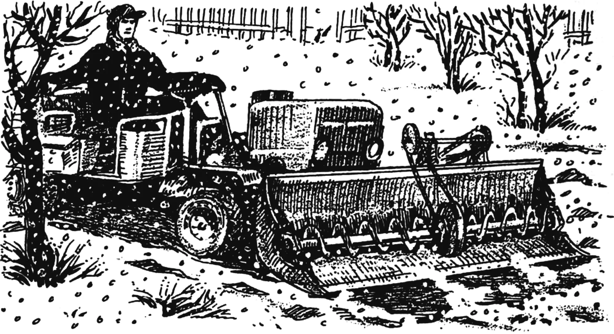
For V. Berezhny, a resident of the town of Valday in Novgorod Oblast, the summer cottage plot is located not far from the town limits, on the western shore of Lake Vysokodno. From home it is a half-hour walk. That is why Viktor Dmitrievich tries to spend his free time on the plot all year round, in the open air.
There is just one problem: the plot is at the very corner of the cottage settlement, half a kilometer from the highway. In winter the road crews still clear that highway, but of course they do not look into the streets and lanes of the settlement — they are not obliged to. And sometimes so much snow piles up that by the time you reach the gate, you have no strength left.
But after a powerful homemade amphibious all-terrain vehicle appeared in Berezhny’s cottage garage, the designer solved the winter-road problem once and for all. When choosing the order of making attachments, priority was given to a snow-clearing mechanism.
Viktor Dmitrievich realized that what was needed was not a simple bulldozer blade but a screw snowblower when he once saw, on the town square, a neat foreign machine deftly dealing with snowdrifts by means of an attachment with an Archimedes screw. Only he decided for himself that two screws were needed, so that they would throw the snow not to one side but to both sides.
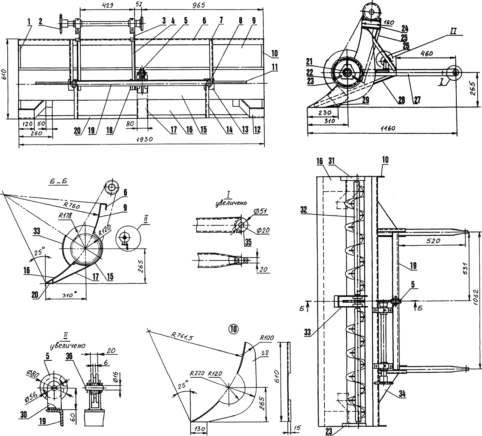
1, 10 — side plates (steel, sheet s2); 2 — drive-shaft sprocket; 3, 24 — drive-shaft mounting brackets (steel, channel No. 6.5); 4, 25 — props (steel, angle 25x25x5); 5 — snowblower lift roller; 6 — upper longeron (steel, angle 45x45x4); 7, 26 — braces (steel, angle 25x25x5); 8, 27 — drawbars (steel, tube 50×1.5); 9, 16 — upper and lower blades (steel, sheet s1.5); 11, 34 — gussets (steel, sheet 270×190, s2); 12, 29 — skids (steel, sheet s2); 13 — side pad (steel, sheet s4, 2 pcs.); 14, 28 — struts (steel, angle 25x25x5); 15 — screw bed (steel, sheet s1.5); 17 — box (steel, sheet s2); 18 — central pad (steel, sheet s4); 19 — beam (steel, angle 45x45x4); 20 — lower longeron (steel, angle 50x30x4); 21 — end bearing housing of the screw mechanism (2 pcs.); 22 — spoke (steel, rod Ø8, 6 pcs.); 23, 31 — arches (steel, strip 25×5); 30 — roller bracket (steel, strip 40×5); 32 — right screw shaft; 33 — sprocket guard of the screw mechanism (steel, sheet s2); 35 — drawbar hinge (2 pcs.); 36 — roller axle (steel, rod Ø16, L50)
After rummaging through his stockpile in a garage corner and finding suitable sprockets, chains, bearings, angles, and sheet steel there, the designer estimated the dimensions of the future unit and in a short time assembled a mechanical helper for himself.
The snowblower body is welded from three steel sheets 1.5 mm thick, bent to a radius: the screw bed, and the lower and upper blades. To keep the body rigid, longerons of angles of different sections are welded on top and bottom, and side plates of 2 mm steel sheet are welded on the sides.
For coupling to the all-terrain vehicle, two drawbars of steel tube 50 mm in diameter are used; steel washers serving as hinges are welded into their slightly flattened rear ends. The front ends of the drawbars are welded to the screw bed through pads — pieces of 4 mm steel sheet.
Overall rigidity of the unit is provided by struts and braces of 25x25x5 mm angle, welded to the drawbars and longerons, gussets of 2 mm sheet steel, and also a cross beam of 45x45x4 mm angle. On the latter, in its bracket, sits a roller over which the cable from the lifting winch, hidden under the ATV hood, is thrown.
The lower corners of the snowblower body are protected from accidental deformation by skids, shaped from 2 mm steel sheet. They are welded simultaneously to the side plates, the longeron, and the blade.
The main working mechanism of the snowblower is the screw unit. It consists of two ribbons that are Archimedes screws of opposite hand and are welded to M6 studs projecting from the screw shafts.
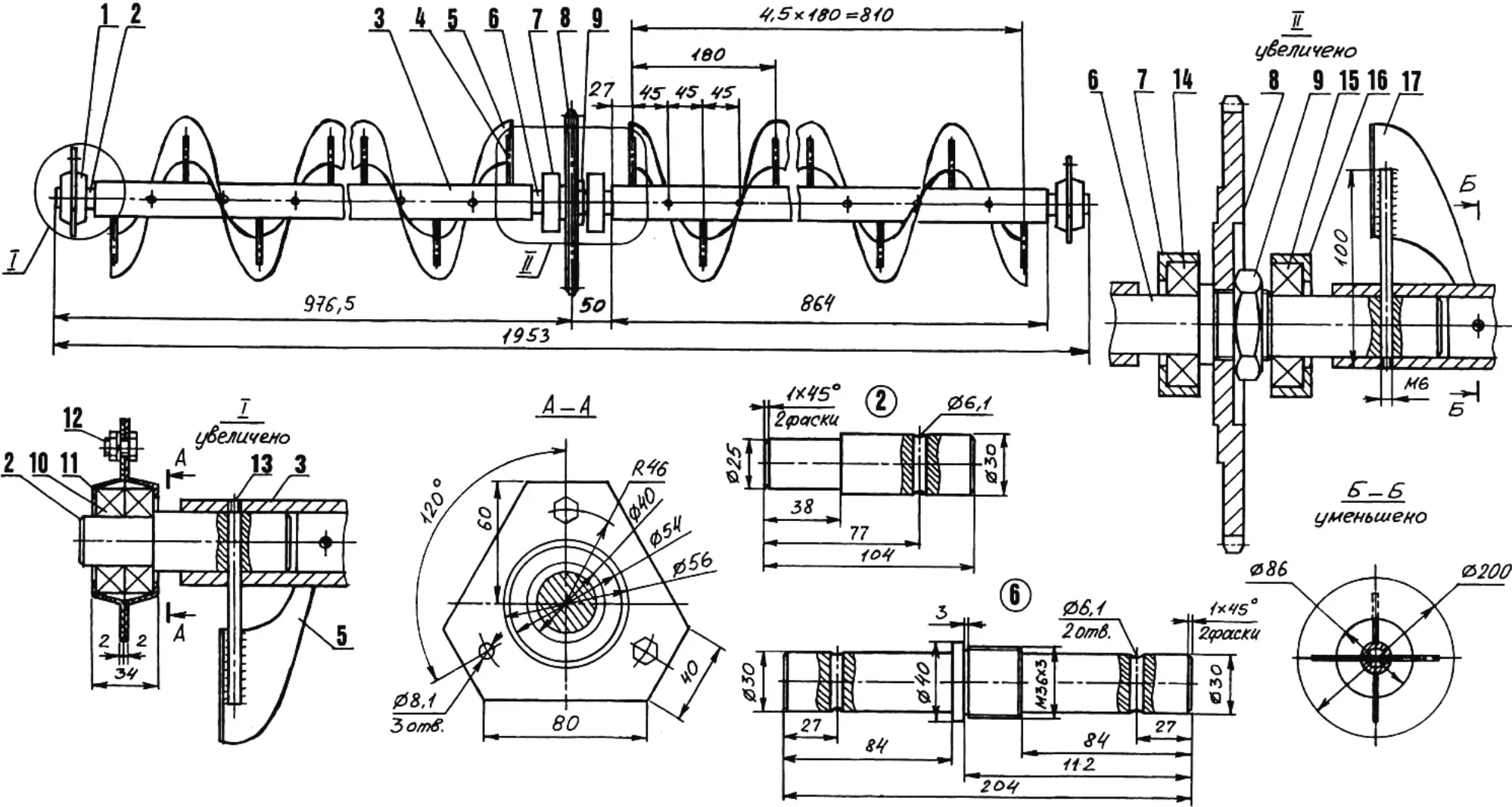
1, 11 — halves of the end bearing housing (steel, sheet s2, 4 pcs.); 2 — end axle (steel, rod Ø30, 2 pcs.); 3 — screw shaft (steel, tube 42×6.5, 2 pcs.); 4, 13 — M6 studs (steel, rod Ø6, 36 pcs.); 5, 17 — screws (steel, sheet s2); 6 — central axle (steel, rod Ø40); 7, 16 — central bearing housings; 8 — sprocket (z = 36, t = 19.05); 9 — nut M36x3; 10 — bearing 160205 (4 pcs.); 12 — bolt M8 (6 pcs.); 14, 15 — bearings 236205
Pairs of 160205-series bearings, enclosed in simple stamped housings, are fitted on the end axles of the screw shafts. The cup halves of these housings are fastened with M8 bolts and, by means of spacer spokes of 8 mm rod, are joined by welding to the arches on the snowblower body.
In the middle of the screw mechanism is a sprocket with 36 teeth and a pitch of 19.05 mm, secured on the central axle by an M36x3 nut. To the right and left of the sprocket are 236205-series bearings pressed into turned housing races, tack-welded to the cheeks of the sprocket guard. First, using the spokes, the end bearings were set exactly on the axis of the screw bed. After that all connecting welds were finished, and the spoke ends projecting outward from the holes in the arches were cut off and ground smooth.
The sprocket of the screw mechanism is protected from the mass of snow pressing from the front by the already mentioned guard, welded to the blades and the screw bed.
Since the strength of the snowblower body was weakened by an opening cut in the middle of the screw bed (for the drive chain to pass through), the body had to be reinforced with a box — a channel-shaped part welded under the opening to the longeron and the blade.
As already noted, the snowblower is driven by a motorcycle chain with a pitch of 19.05 mm, stretched between the sprockets of the screw mechanism and the drive shaft located on the left on the upper longeron of the snowblower body.
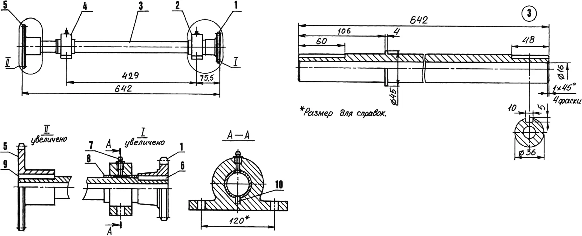
1 — driving sprocket (z = 15, t = 19.05); 2, 4 — plain-bearing housings; 3 — shaft; 5 — driven sprocket (z = 22, t = 19.05); 6, 9 — parallel keys; 7 — grease fitting 1M10x1 (2 pcs.); 8 — bearing bushing (antifriction cast iron AChS-1 or AChK-2, 2 pcs.); 10 — retainer (pin Ø8, L12, 2 pcs.)
The drive shaft is a simple reduction unit that transmits torque to the screw mechanism from the power take-off shaft on the ATV engine. The sprockets and plain bearings (cast housings and bushings) of this reducer were taken from agricultural machines. The sprockets on the shaft are fixed with keys, and the bearing bushings of antifriction cast iron are fixed with pins, whose seats were drilled through the threaded holes in the housings with the grease fittings removed.
The assembled drive shaft is mounted on two brackets of channel No. 6.5 welded to the upper longeron. Since the length of the brackets considerably exceeds the width of the longeron’s horizontal flange, props were needed. They were cut from 25x25x5 mm angle and attached by welding between the brackets and the pads on the screw bed.
As a result, the load path of the snowblower was arranged so that all loads arising in the structure while “cutting” through snowdrifts are transmitted through the props, struts, and braces to the drawbars and then to the ATV body, where they are closed.
After testing and final fine-tuning, the unit was thoroughly cleaned of rust deposits, treated with an anticorrosion compound, primed, and painted light brown. It came out no worse than a factory product.
And now, when the streets of the cottage settlement are blocked by snowdrifts, Viktor Dmitrievich hangs the snowblower on the front of the ATV and drives slowly to the highway and back. Slowly on purpose, so that the neighbors’ fences are not accidentally damaged under the pressure of his snow “salvos.” After such a pass along the street leading to Berezhny’s gate, one can stroll as if on a city street.
“Modelist-Konstruktor” No. 2’2004, A. NIKOLAEV
Recommend to read
 WARDROBE WITH RADIATOR
The Idea of this cupboard gave me your magazine. In one of the rooms published design window of the refrigerator and the vegetable box in the window sill niche. I liked it, and I did... ANTENNA IN HASTE
Anyone who at least once in a lifetime chance to deal with wires, you can make original TV antenna (Fig.1) no worse than industrial zigzag. The idea of this simple device I made in...
