
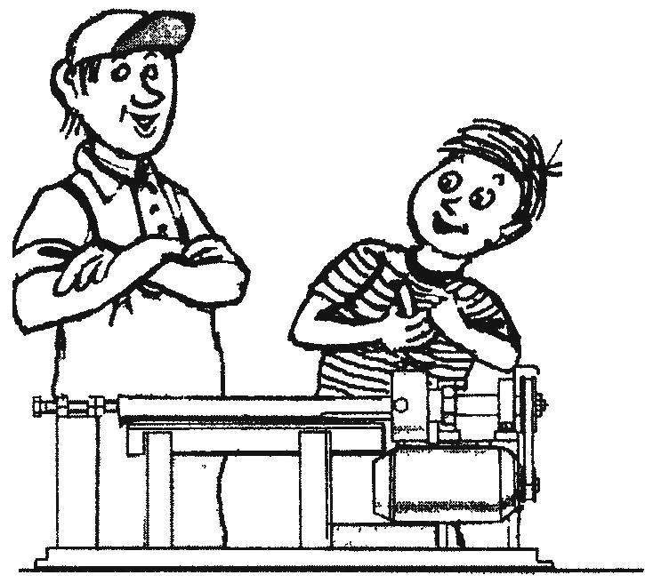
 Small lathe for wood can actually be very simple. The overall layout and main components are known is a base with rails, front and rear headstock; the first is integral with the frame, the second movable in the guide; on the front of the headstock spindle is mounted with the actuator on the rear — support center. In fact, the feature of the machine, its simplicity and the possibility of manufacturing craftsman are determined by the design of main components.
If you wish to produce a machine at home first of all have to decide how to drive. Small woodworking lathe it can be an electric motor from a washing machine or other domestic appliance with a power of 200-500 watts at 1400-2200 rpm, preferably with a finished V-belt drive In the generated machine used drive washing machines SMR-1,5
Frame was made of steel angles 45×45 mm from old beds, welded to form a flat rectangular frame with a rack (front head) for installation of the spindle. The spindle is made in the form of a shaft with a glass-cartridge for fixing of the workpiece on one end and a pulley belt transmission on the other. The spindle shaft is assembled with two ball bearings No. 203, each of which is mounted in the housing, and the bearing housings are mounted on the front of the headstock bolts M8 tailstock welded from steel angle and plate resting on the bed slideway, the Locking of the tailstock is provided another plate in contact with shelves at the bottom corners of the guides and associated with the tailstock bolt M8 To the top plane of the tailstock welded two M8 nuts, which are screwed back center (bolt М8х60, which is processed under 60°). In the operating position it is fixed by the lock nut.
The focus for the instrument is a U-shaped frame, privernutuju the M8 bolts to the frame. As a tool used chisels of a length of 300 mm, made of old files. When the chisels are based on the upper area of emphasis
In the manufacture of the frame, special attention should be given to the Assembly guide, the two longitudinal parts of Their parallelism and coincidence of the planes of the upper shelves need to provide prior to welding by any means of fixation: liners, clamps, etc.
The bed slideways to be used as a base to provide the most relevant qualitative features of the machine —align the front and support centers. First, you need to weld the tailstock two nuts, screwed to the bolt — support center. Before welding them should be fixed in the middle, ensuring the parallelism of the axis of the support centre and Then the guides in the cartridge assembled with the bearing supports of the spindle to insert the front and center — specifically sharpened to a cone rod. The axis of the center must strictly coincide with the axis of the spindle. It is easy to check for radial runout of the side surface of the center of turning of the cartridge.
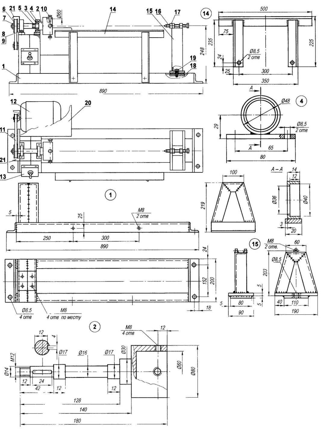
Woodworking lathe:
1 — frame(steel area 45×45), 2 — spindle with cartridge, 3 — ball bearing 203 (2 piece), 4 — the bearing housing (2 PCs), 5 — spacer, 6 — pulley, 7 — nut M12 8 — bolt М8xl8 (4-piece), 9 — spring washer (4 PCs), 10 — Cams (bolts М8х40, 4pcs.), 11 — V belt 500, 12 — drive motor, 13 — pools of management, 14 — emphasis (steel area 45×45), 15 — tailstock, 16 — support (rear) center, 17 — nut M8 18 — plate (steel sheet s5, 190×80), 19 — bolt М8х18, 20 — the shield of the motor, 21 is a protective screen transfer
Spindle with front center need to put on the front of the headstock so that its axis was parallel guide rails and, furthermore, coincides with the axis of the support center. The coincidence of the axes of the centers easily checked by eye with their combination after appropriate rearrangement and fixing on the rails of the tailstock. Only then can you drill four holes threaded M8 on the front of the headstock through the corresponding holes in the bearing housing for fixing
After Assembly you must check the ease of rotation of the spindle and the alignment of the front and support centers and lock the bearing housings with an oven MITT
The motor is attached to the rear surface of the headstock. At first the place holes are drilled, they are then cut, and moving the mounting bolts of the engine in the slots provided by the V-belt tension. To avoid injury the transfer belt and both pulleys are covered with a casing.
The control panel is mounted on the front of the headstock. It is a box with capacitors inside and a toggle switch for power off of the engine on the front wall. The motor from the ingress of chips and dust is closed by a screen of sheet aluminium.
In conclusion, let me remind you about the features of the machine. Tool (chisel) should be kept perpendicular to the work surface. When processing the end surfaces as a support you can use the tailstock centre Support is used for the treatment of long (>150 mm) and thin workpieces. When working near the supporting center of the chip to be removed is smaller, so as not to disturb the alignment.
Yu. KARIMOV, p. Khurba, Khabarovsk Krai
Recommend to read
 NO BOX, BUT THE BOX
Often, when the equipment of the bathroom closing the space under the bath, using a special shield or laying a wall of brick. In the latter case, the clutch leave the window for... HIS LAST
"Every cricket stick to his last" — says the proverb. The same can be said about the tool: it is convenient, when each of them is not only reserved, but also equipped with appropriate...
