 In recent years in our country and abroad is rapidly developing a new kind of consumer electronics device for home games. The name given to a special prefix to the TV, allowing you to create on the screen the imitation of various sports, military, and other games. These devices are built on the basis of the so-called telegraphic circuits or large integrated circuits.
The console connected to the TV antenna input, and displays an image, e.g. a tennis court, rackets and ball. By manipulating the handles, the players “chase” the ball (a light spot) on the screen as in real tennis.
Game show give the players the illusion of participating in this sports competition, develop attention, train your dexterity and reaction time.
We offer our readers a simple device simulating the game of hockey (forward vs goalkeeper) on the screen of the oscilloscope the school OES-61; such devices are in a high school physics classroom, in the laboratories of radio engineering and electronics syut, Palaces and Houses of pioneers.
The appearance of the console — figure 1. The front panel contains counts for the number of goals and shots taken on goal, the power switch. On the top panel there is a knob (rotating it, “striker” moves “puck” — a luminous spot on the oscilloscope screen) and the red light, the locking contact “washers” in “gate”. Using chestiile cable to the console connected to the button, clicking on which goalkeeper can lock the gate.
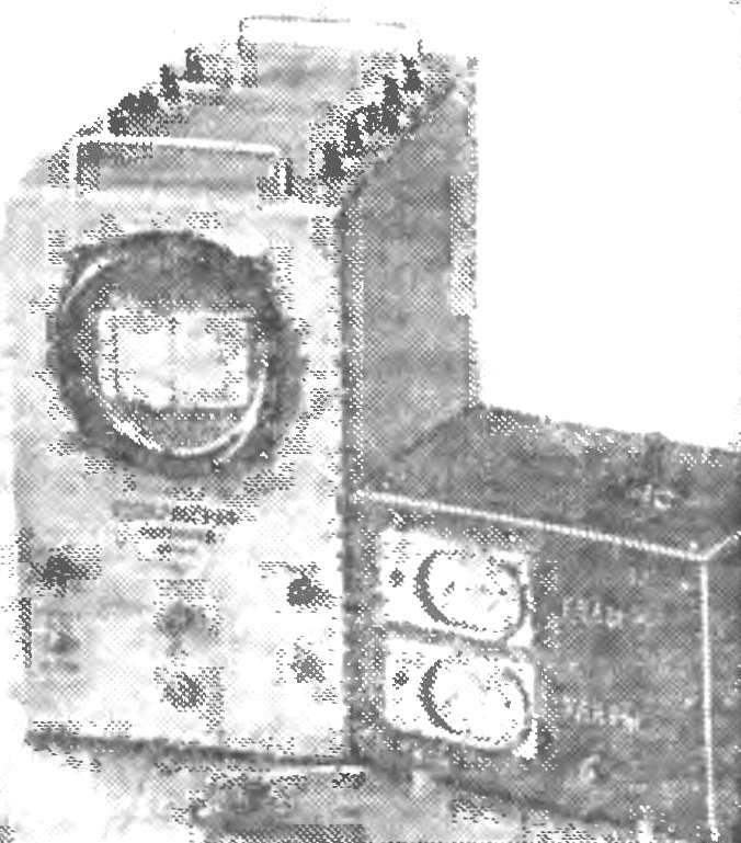
Fig. 1. Appearance gaming setup.
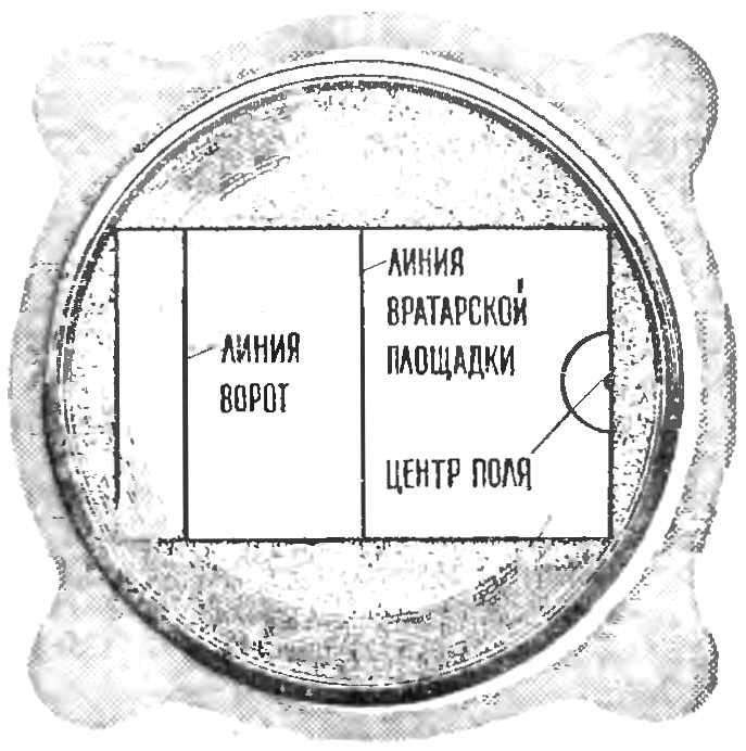
Fig. 2. The playing field.
On the screen of the oscilloscope is applied to the stencil of a thin transparent acrylic glass or Plexiglas (Fig. 2) layout the left half of the hockey field from the gate to the center. Striker punches like bull—hockey from the penalty spot. Line marking must be done in color, then you’ll see them on the screen and thin as not to overlap the spot of the washer. For simplicity, in this game device gate width equal to the width of the entire field.
The essence of the game is as follows: forward, turning the handle, keeps the puck across the field to the gate. Having brought her to the line of the goal area (penalty box rules of the game to throw is not allowed), the forward movement of the handle directs the puck. If the striker beat the goalkeeper and the puck crossed the goal line, a red lamp, the locking contact. The counter will count the goal. The goalkeeper protects the gate by pressing the button: the movement of the washer is limited, and it stops without crossing the goal line. And that the goalie didn’t block the gate for a long time, the design includes a time limit for the snap action of the goalkeeper. After 0.5 s it will be immediately punished — light up the red lamp, and the counter counts down a goal. Because the goalkeeper can push the button not longer than 0.5 s. However, if the puck crossed the line of the goalmouth (even if not throw on goal), the goalkeeper can block the gates all the time while the puck is in the goalie area.
Should the puck get out of it again comes into force a time limit for the lock gates. The game result is obtained by comparing the readings of counters (the number of strokes made by the attackers, and the number of missed goals).
Schematic diagram of the device in figure 3. Motion control of the puck on the field is carried out using a rocker mechanism (Fig. 4). Moving the handles forward or backward causes the rotation of the engine, the variable resistor R6, to the right or left — R5. (Such devices are used in equipment for proportional control.)
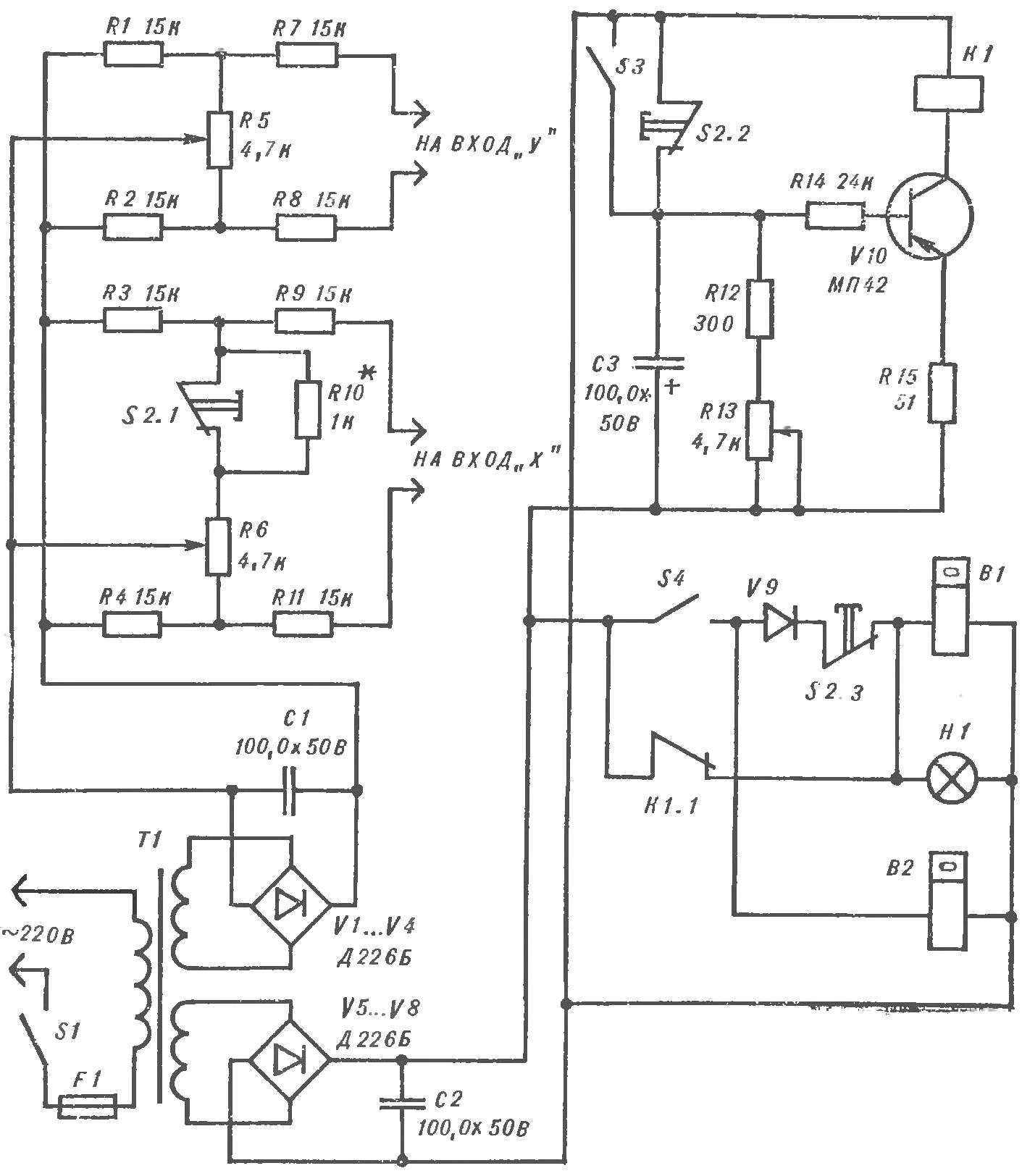
Fig. 3. The concept of consoles.
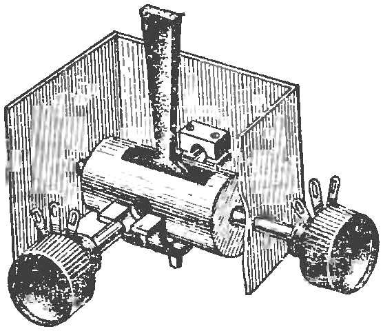
Fig. 4. The rocker mechanism to control the puck.
Simultaneously with the change of the resistance of resistors R5, R6 to increase or decrease the voltage on the deflecting plates of the oscilloscope a luminous spot is displaced accordingly in the vertical or horizontal direction. Thus, moving the handle of the rocker mechanism, hold the puck at any point on the screen.
When the puck reaches the goal line, closes contact S4. And if the goalkeeper did not have time to click S2 lock the gate, turn on the lamp H1 and the B1 counter counts a goal. When the goalkeeper manages to push the button S2 before the striker will carry the puck across the goal line, the voltage divider circuit is included a series resistor R10 (opens contact S2.1), which limits the voltage supplied to the horizontal deflecting plate located on the side of the gate, thus giving the puck to cross the goal line.
When moving the control stick forward contact of switch S3 (Fig. 5) is closed at the moment when the puck crosses the line of the goalmouth. The semicircular bracket connected with the control knob, is attached to the rod, which first closes the contact S3, and then S4. The first provides a supply of negative voltage to the base of transistor V10 is the goalkeeper by pressing the button S2 can permanently block entry (relay K1 will not be turned off). The second, which closes at the moment of crossing the puck to the goal line, turns counter B1 count heads. In addition, the contact S4 include a counter B2 fixing the number of shots on goal.
The time limitation of the lock gate provides time relay transistor V10. While the a goalkeeper button S2 is closed (gate is open), a negative potential is supplied to the base of transistor V10. It remains open and the relay K1 is turned on. Contact K1.1 is open and the circuit of the counter B1 heads open. As soon as the Keeper will close the gate (terminal S2.2 is opened), the capacitor C3 begins to discharge through the input circuit of the transistor V10. The current in the circuit of its base will gradually decrease and after some time, relay K1 will turn off. Contact K1.1 closed, lamp lights H1, noting a goal, the counter B1 it will lock. Time turn-off delay relay K1 set variable resistor R13 (remember, it is about 0.5 C).
It should be borne in mind that at the time of pressing the S2 there is a effect of “ejection” pucks out of the gate (this is caused by connection of additional resistor R10).
The device features the following details: K1 relay RES-10 (RS4 passport.524.308); B1, B2 — counter SB-1M/100 or SEI-1; S1—toggle switch TV1-2.
Button S2 improvised, made of contact groups of the relay or the phone key.’ The variable resistors R5 and R6 redone. Their body is gently opened. In glinkovo plate, covered with a layer of graphite, which moves the resistor, and the housing drill hole Ø 1 mm so that the angle of rotation of the engine to the right of contact was 90° (Fig. 6).
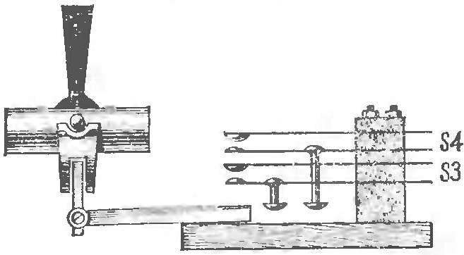
Fig. 5. Contact “e-hockey”.
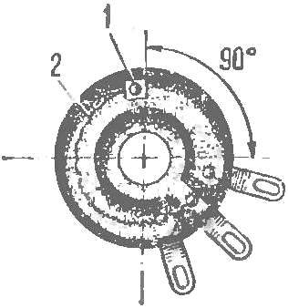
Fig. 6. Alteration of the variable resistor:
1 — copper rivet, 2 — wire connection.
Inserted into the hole in the copper rivet, pre-paving for a hat a piece of phosphor bronze (for best contact rivets with graphite coating). Rivet, and the left output of the variable resistor is connected by wire.
Control knob rocker mechanism is mounted so that its angle of movement forward-backward and left-right was not more than 90°. The sliders of variable resistors must move in the designated sectors from the right contact to the copper rivets.
The values of the resistors R1 — R4, R7 — R9, R11 pick up such that in the extreme positions of the control stick luminous spot on the oscilloscope screen did not go beyond the playing field.
The value of resistor R10 set such that when the button is pressed and S2 is completely derived forward the control stick a little glowing spot did not reach the goal line.
Transformer core collected from the plates Ш20Х20. Network 2750 winding comprises turns of wire of PEL 0,15; winding II — 1380 turns of wire of PEL 0,15; winding III — 300 turns of PEL of 0.31.
The device is connected to a four-wire cable with inputs X and y, located on the rear panel of the oscilloscope. Before the game handle the “focus” of the oscilloscope refocuses slightly glowing spot on the screen. Then it will look like a circle-the puck.
You can use any other oscilloscope electrostatic deflection of the electron beam.
B. IGOSHEV, Sverdlovsk
Recommend to read
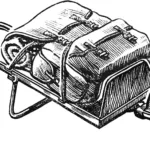 BACKPACK ON WHEELS
Our housewives, especially elderly ones, have long appreciated the shopping cart — a small two-wheeled cart with a bag attached to its frame, resembling a tourist backpack in shape. How...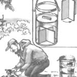 ASSORTED TO BASKET
Lightweight and durable it turns out tuesok of birch solid "pipes", accurately taken with an older birch deck. It is good to walk with him in the forest for berries and mushrooms....
