
 Many of us have been fascinated by the exploits of Ivanhoe, Lancelot, read about the struggle and death of evpatii Kolovrat, admired the stories of John. P. P. Tolkien. These interests were awakened the interest in the distant past, gathered like-minded people and dreamers in the clubs history and reconstruction.
They explore the ancient way of life and everyday life, recover forgotten technology. Is of interest to medieval siege equipment. The magazine “M-K” already published in its pages a description of the models throwing machines of the era (“M-K” № 1 for 2010). In this article, we offer readers understand the structure of a trebuchet (from the French. trebuchet – “the scales with a yoke”) – siege weapons (in Russia it was called camalet, sling, defect), which was used in the middle ages when storming towns and castles, and make it a small copy.
Our trebuchet will be small-it will be placed on the table. Shells can also serve as balls, rolled up clay, if you let them dry they will be durable enough to withstand a few shots. They can also be annealed, as is done with pottery. You can make these balls of polymer clay – it does not require firing, and after curing in the oven durable enough for our experiments. Also unable to purchase a table kicker and have a good time.
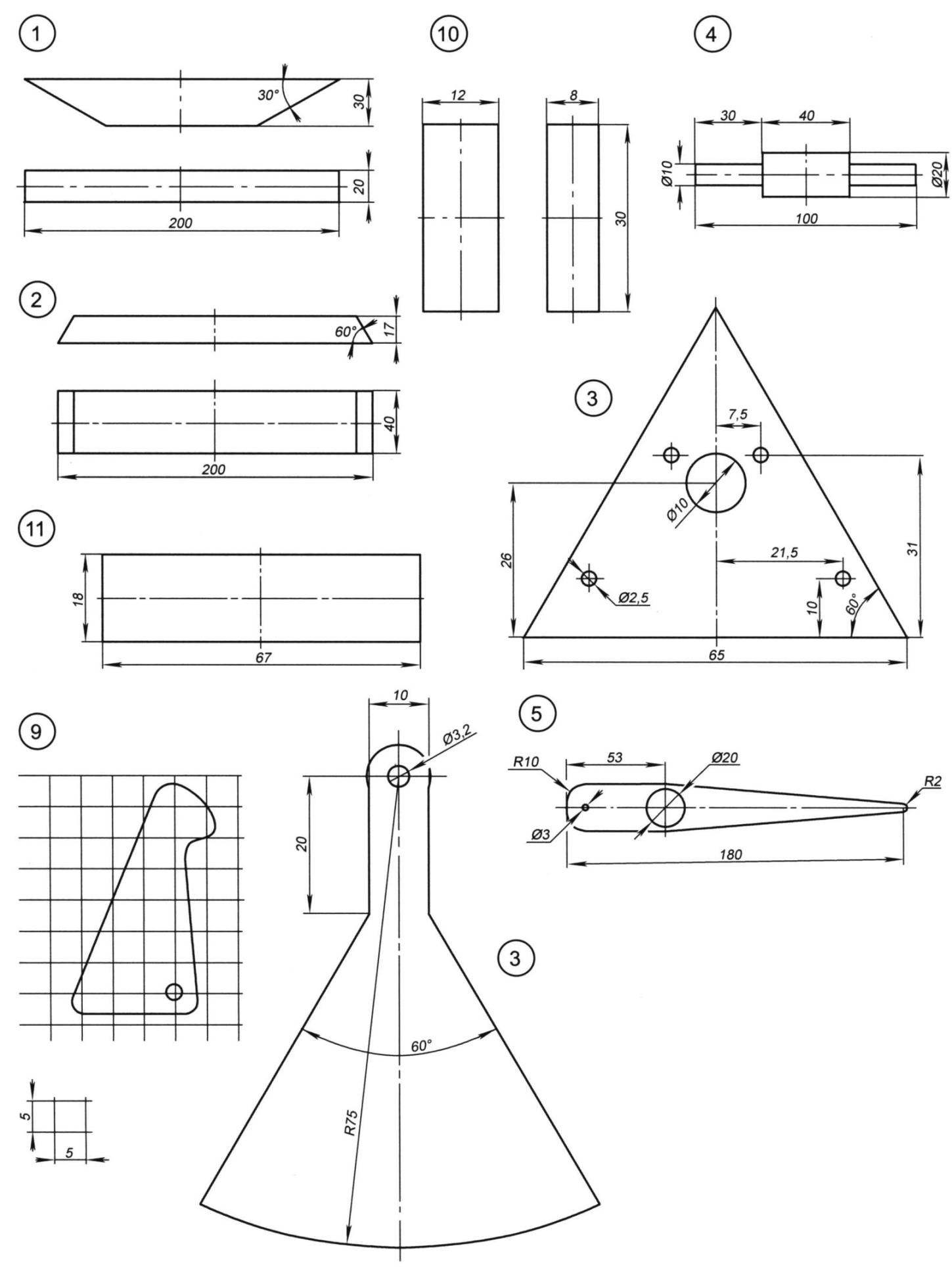
To create the trebuchet, we need wooden bars with section 20×30 mm, trim 4 mm construction plywood, small nails and screws.
Of tool – a knife, a chisel, fine teeth wood saw or hacksaw, hand jig saw, screwdriver. I still used a desktop lathe for grinding axes.
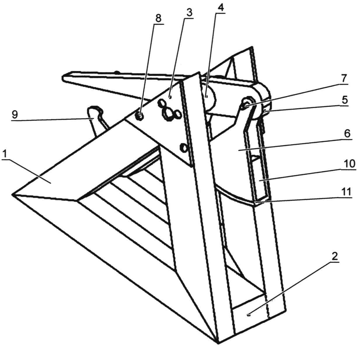
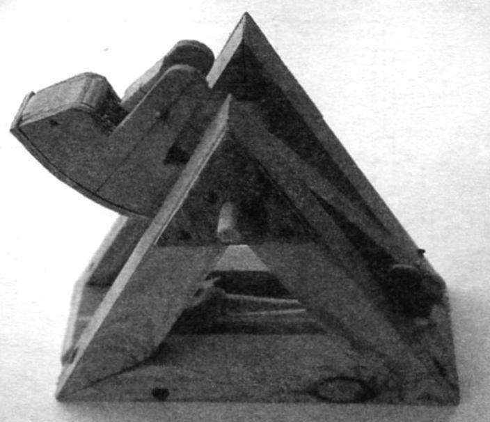
Working model trebuchets:
1 – rack (pine 20x30x200); 2 – base (pine 17x40x200); 3 – a lining (4 mm plywood); 4 – shaft (pine, 020); 5 – rocker (pine 10x180x25); 6 – cheek basket (4 mm plywood); 7 – axis of the basket (pin М3х30); 8 – screw 2,5×20; 9 – trigger (4 mm plywood); 10 – the wall of the basket (8 mm plywood); 11 – the bottom of the basket (4 mm plywood)
A feature of the design is a failure from trying to follow the exact design of prototype frame the shape of an equilateral triangle as the most stable figure.
To build triangular trusses bars first attached the bottom with screws. Top corner, in which is drilled a hole for the axis of the rocker arms, is fixed a plywood plate (POS. 3) which is screwed by four screws 3×20 mm cross-section with a semicircular head.
Between supporting truss fastened strap cross-section 40×20 mm (POS. 2). The strap is made in a semicircular chisel sampling, which serves to guide the projectile. I recommend to take the time to do this sampling before the installation of the rocker – in my case the rocker arm was positioned along the axis of the sample, which led to the deterioration of the accuracy.
Collecting both farm and attached to one bottom bar, you need to specify the distance between the upper ends of farms – inaccuracy in the manufacture of the bottom bracket, the non-parallelism of the lateral faces can change the distance between the peaks of the trusses. Therefore, attaching the parts to each other, measure this distance, and if vertices is 2 – 3 mm, you can simply specify the length of the cylinder 20 mm of main shaft (POS. 4). Also, while it is not necessary to drill into farms the hole for the axle is best to do when the axle is machined and ready for installation on site.
Securely cementing the farm, clamps, drill hole for axle.
Those who have a drill press, others are thoroughly soaking right angle relative to the plane of the trusses. Fit the axle and the rocker arm in place – it should freely rotate on the axis, and it should not be skewed in any direction.
Now make a counterweight. For him, first with a jigsaw, scrollsaw side plates-cheek (POS. 6) , we clamp them in the vise and the workpiece is, the degree of identity depends, will not counterbalance the curves even at a glance. The following items are end wall (POS. 10) – they need to make more of thick plywood, to the Assembly of the counterweight the wall does not split the nail. They also need to be handle in a vise package. Now gather these four items together -get the side straps to the cheeks of the Shoe nails of the cross section 1×14 mm (for two nails on each side of the bar). While nails should be placed so that they were not too close to the edge, otherwise the parts will break. Now the counterweight is left to do the bottom. In the completed Assembly, giving her a piece of paper, measure the dimensions of the bottom of the basket (POS. 11). We cut it from thin plywood and a screw section 2,5×12 mm is attached to one of the end walls. Given that it is already four nail before screwing the screw need to drill a hole with a diameter of 1.2 mm.
The next step is to bend the bottom of the counterweight to form the bottom. Since we have a convex, it is relatively easy to bend the plywood right on the counter – that’s why we secured one end of a lower strap. Efforts at bending appear sufficient, and one to screw the parts together does not hold. Therefore, install the clamp that will compress the fixed end of the bottom plank and the end wall here and need a large thickness of the side wall, otherwise it would just be crushed.
The bending is carried out in a heated state. In boiling water, aged basket counterweight for 2-3 minutes, then removed and the second clamp to the second side wall is pressed against the loose end of the lower plate. When the plate is pressed gently all over the bottom of the counterweight, to keep the design together with clamps until dry (I have them lay on the windowsill all night, that was enough). After removing the clamps, check the quality of the clamp and immediately fasten the second end of the lower strap the same as the first, a screw section 2,5×12 mm.
The basket must be filled with goods – these can be small details, tightly Packed clay or, like me, filled in the basket lead. The finished basket try on a yoke and fasten with a hairpin М3х30.
Now the narrow end of the rocker arm you need to fix the sling. The sling is made of only three simple parts – 2 segment 3-mm twine with a length of 150 mm and a rectangular piece of fabric (any sufficiently strong – for example, old jeans) size 100×10 mm. Departing from the narrow edges of 5 mm, will make the incisions through which skip over the segment of rope. If the fabric tends to crumble (as, for example, the same jeans), you will need to glue the edges with glue “Moment”. Sling ready, fasten it to the yoke. One end I attached, shoot a rope clip. On the second string, made a loop, which is fixed by plugging in a match, and wrapped the folded end of the thread with glue – so it turned out neater than trying to tie the knot. This loop fits over the hook -Shoe nail cross-section of 20×1 mm, using needle files devoid of the cap and pressed into the end of the rocker arm. Sticking out only 5-mm tip of the nail.
Well, the trebuchet is ready to throw the kernel into enemies. However, to make a shot, releasing your finger hold the end of the rocker arm, uncomfortable. Will do the trigger.
First, measure out 30 mm from the narrow end of the rocker arm and tighten the screw with a semicircular head so that between the cap and yoke left 5-6 mm. the Trigger is attached to the rail section screw 3×20 mm round head. Before you mount, make sure it securely holds the yoke for the screw. If the yoke slips out at the slightest movement you can deepen the groove in the trigger or move the point of attachment slightly back and up. If for shooting you need to push the hook so that it is not clear over the rail, then slide the point of attachment down or in structures or sawed the hook. All of these operations on the fitting should be done before final fastening of the hook, otherwise where will need to screw in the screw for it, very soon will not remain a live place. Screw for fixing – again 3×20 mm round head.
Now, check the trigger hook, you need to lock the position of the rocker shaft. I did it the simplest way – I drilled the main shaft on both sides of the rocker arm using a 1.5 mm drill bit and stuck in these holes the pieces match. A guide groove for the projectile I had by this time ready, but I recommend you to do it right now, after fixing the position of the rocker.
So, after a few test shots and determine the main parameters of the resulting weapons can raise an army of orcs storming helm’s deep.
After the first instance of a trebuchet was assembled, I found on the Internet detailed descriptions of the medieval prototype of my design. There were drawn and information about the maximum ranges and identified in the age-old wars optimal ratios for structures of this type. Interested in the question also easily find this information. Give your followers the opportunity to improve my proposed design.
N. BEACONS, Ufa, Bashkortostan
Recommend to read
 INVISIBLE “HOOK”
Even a small picture to decorate her wall, need something to fix. And here a nail is taken, torn Wallpaper, exposed wall, especially in the most modern of them is not so easy to... AEROBATIC TRAINING
Develop some automaticity in managing the cord of the model during takeoff and horizontal flight, you can begin to build more complex apparatus. It will help you to learn how to perform...
