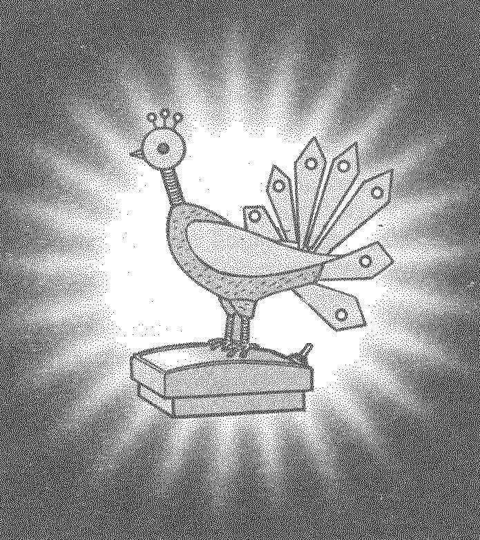
 A souvenir depicting fairy-tale “the Firebird” with the use of LEDs, can make even novice hams. The details of the electric circuit, except the LEDs are placed inside a plastic soap dish suitable sizes, are the basis. Two red (or orange) led, is inserted in place of eyes, connect to the unsymmetrical multivibrator, and seven flashing LEDs in the tail feathers twinkle themselves. Details of the scheme: VT1, VT2, R1, R2, C1 is located on the PCB about the size of 40×20 mm, which is fastened inside the base by two screws M4. The power switch (microtubles) is displayed on the top cover.
As the power supply uses two type element 343. Seals the battery compartment are glued to the inner side walls of the housing and are intended to ensure that the batteries are not dangling in clusters and are firmly joined to the contacts. Perhaps sizes of a partition and seals will have to change in accordance with the existing case (e.g. large gaskets to make it thicker or not at all). Contacts are made of sheet brass or even tin cans. In the latter case, the contact areas of nutrition elements from a metal contact plates you must remove the protective lacquer. Contacts are attached to the inner wall of the housing and the bulkhead glue (e.g., “Point-1”) and is additionally pressed with pliers. To the output terminals of the battery podpisatsja two wires. These wires leading from the housing to the LEDs simultaneously to form the skeleton of the feet.
Then feet up to the knees are formed by obvisly these wires thin red or yellow wire from the breakout cable. The fingers are made of the same thin single-core wire by its outer around the Central veins. The connecting wires are passed through holes in the top cap and with its inner side stick to “the Firebird” was on the ground and did not fall.

The layout of parts and components in corpus-based:
1 — the lower part of the base; 2 — circuit Board, 3,12 — small seals (plexiglass, s3); 4 — contact “+”; 5,9 — batteries, 6,8 — large seals (3 mm plexiglass, s3); 7 — contact “+-“, 10 — Kontakt “-“, 11 — baffle (non-foiled getinaks); 13 — cover of the case; items 4, 7, 10 — is made of 0,8 mm brass sheet

A circuit diagram of a souvenir with asymmetrical multivibrator and flashing LEDs in the tail feathers and unblinking — eyes

Souvenir items:
a — wing (veneer s0,5), b — feather of the tail (veneer s0,5) in — leg (wire)

A circuit diagram of a souvenir with a symmetrical multivibrator to blink unblinking LEDs

The skeleton of “the Firebird”

The form of a souvenir “the Firebird” back
The skeleton of “the Firebird” was formed just two matches, one the trunk, another the neck. The findings of the LEDs-the eyes are soldered together and primatyvajutsja thread with glue to match the neck. The beak is made of two wooden wedges. The items forming the wings and rump, cut from veneer and covered with nitrocellulose lacquer — three times from the outside, once inside. To the tailings LEDs podpisatsja wires from the back side of the tail glued over a thin Dacron (film from flower bouquets). After completing the necessary electrical connections the skeleton of “the Firebird” wrapped wool thread separately formed head, the ball, the muscles of the legs, neck, torso, primatyvajutsja and tail feathers. The crown is made of three pins with a plastic head. For reliability, the toes stick to cover transparent glue “Moment-crystal”. Details located on the cover, must join the parts in the housing with wires of sufficient length so that the box can be opened for replacement of batteries. As eyes you can also use green LEDs, and as parts of the tail — flashing red or orange. In the absence of flashing LEDs, you can use normal, connecting them to the symmetric multivibrator.
The schemes are the following parts Condensers — K50-35, K53-1, K52-1 or other electrolytic, preferably new or at least youngish, because, otherwise, possible failures in the work. Resistors — MINTS or other. Transistors: VT1 — KT361, КТ203, КТ209 with any letters, or any other low-power silicon p-n-p, VT2 — KT315 (except AND), КТ603, КТ3102 with any letter or other n-p-n, can withstand current up to 100 mA (the same applies to VT1, VT2). LEDs НL1 and НL2 — 5 mm high-brightness, but there may be other types, for example, АЛ307 L, I. it is Desirable that the LEDs used for the eyes were the same color and the same size.
A. BRANITSKY, Minsk


