
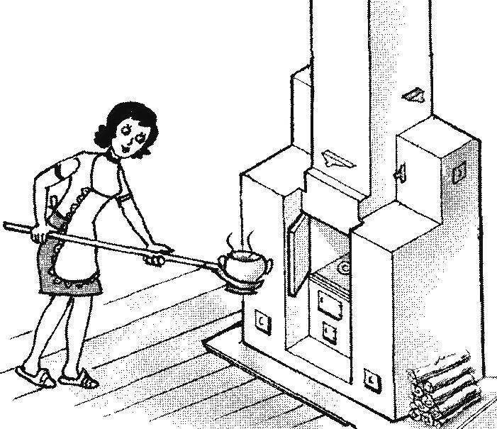
 The practical necessity of placing a furnace and a fireplace in a small area of the room led to the creation of a single “hybrid” structure of kamiloiki with a common Foundation and chimney. The specific location of its components contributes to the expansion of functionality and increase the heat output of such heating and cooking stoves (stove or fireplace), improving the environment of the room.
The stove (Fig.1) has a cooking chamber 1, combined with the furnace space 2 with recessed fireplace furnace 3, which is simultaneously the firebox of the furnace with podduvalom and grate. Chimney plate 4 with the obligatory one or two ring holes provides independent and joint operation of the furnace 3 furnace and the furnace and 2 fireplaces. To increase the area of thermal contact of the furnace with the furnace room 3 has two opposite flue 5 in the brick body of the furnace 6, representing two of the heat exchanger with a chimney controlled by dampers 7 and 8. Symmetrically located relative to the heat exchangers of the furnace 3 constitute the side walls of the combustion chamber 2, connected to the chimney through the fireplace damper 9. The furnace flue is blocked by the valve 10.
For ignition furnace in the winter and summer operation of the heat exchanger on the left contains a by-pass flue is controlled by the valve 11, which corresponds to the mode “a” on the diagram of dymooborotov when the valve is closed 7 and 8 and 10 open furnace flue.
A distinctive feature of the furnace is the overlap of furnace chimney after heating of masonry with the running of the furnace, with the transition to the fire mode afterburning of fuel, which increases heat out of the furnace, since a large part of the surface of the heat exchanger will give up heat to the room without any loss through the chimney. In this case, before closing the furnace chimney with the flap 10 open burner openings of the kiln plate 4 when the damper is open 9 fireplace chimney used as vent hoods while cooking, preventing the ingress of foreign smells in the room (the “g” in the diagram of dymooborotov). Additionally, the window of the cooking chamber may be covered by doors 12, which are also closed when the afterburning fuel to prevent excessive exhaust of air from the room through a fireplace chimney.
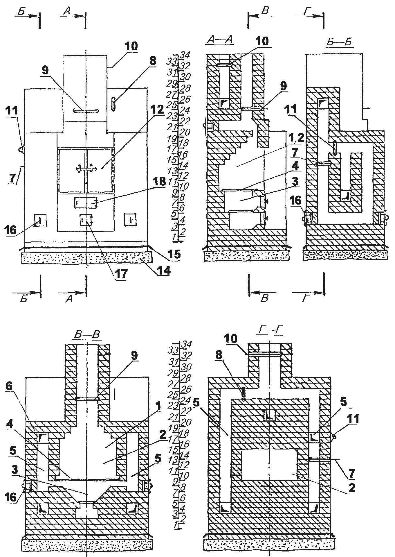
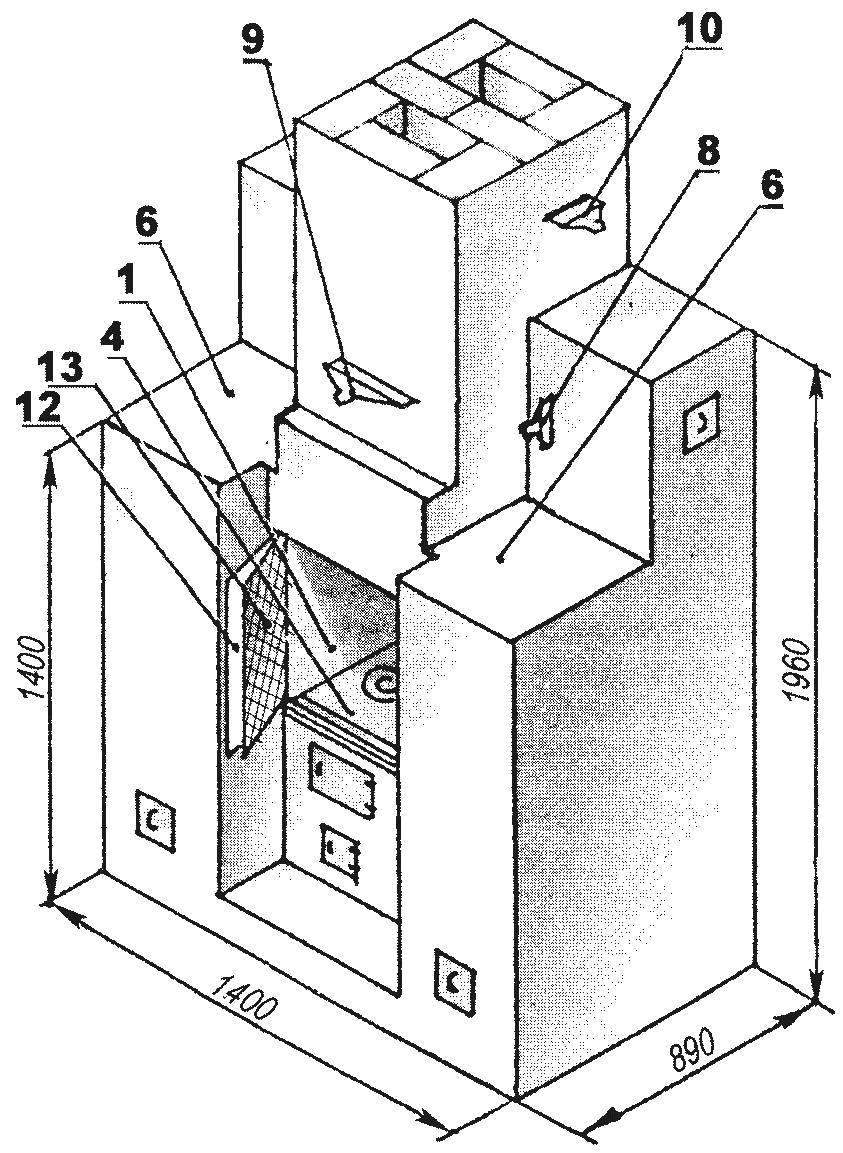
Fig. 1. Casinoice:
1,2 — cooking-furnace and chimney chamber; 3 — furnace; 4 — furnace stove; 5 — flues; 6 — oven body; 7 — valve of the left heat exchanger; 8 — right valve of the heat exchanger; 9 — the valve of the fireplace chimney; 10 — damper furnace flue; 11 —catch ignition; 12 — the door of the cooking chamber; 13 — fireplace door mesh; 14 — Foundation 15 — waterproofing; 16 — cleaning (4 PCs); 17 — the door blew; 18 — fire door
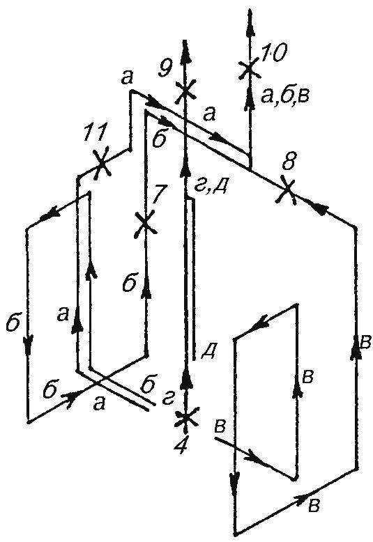
Fig. 2. Scheme dymooborotov:
“a”—mode firing furnace; b—heating of the left heat exchanger;—the right heating heat exchanger; g—mode afterburning of fuel; “d”—fire mode
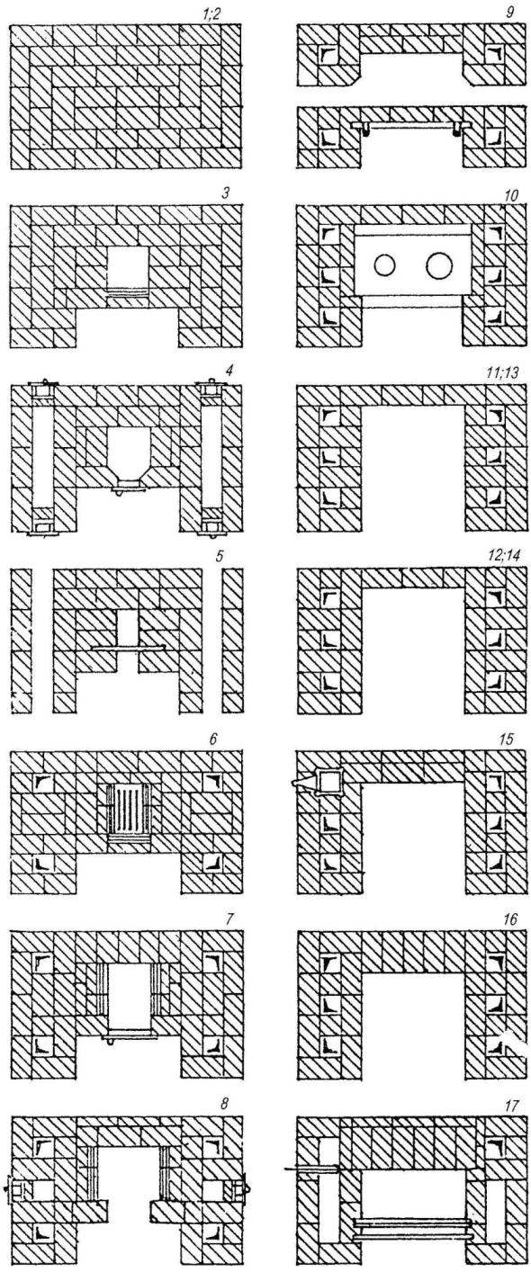
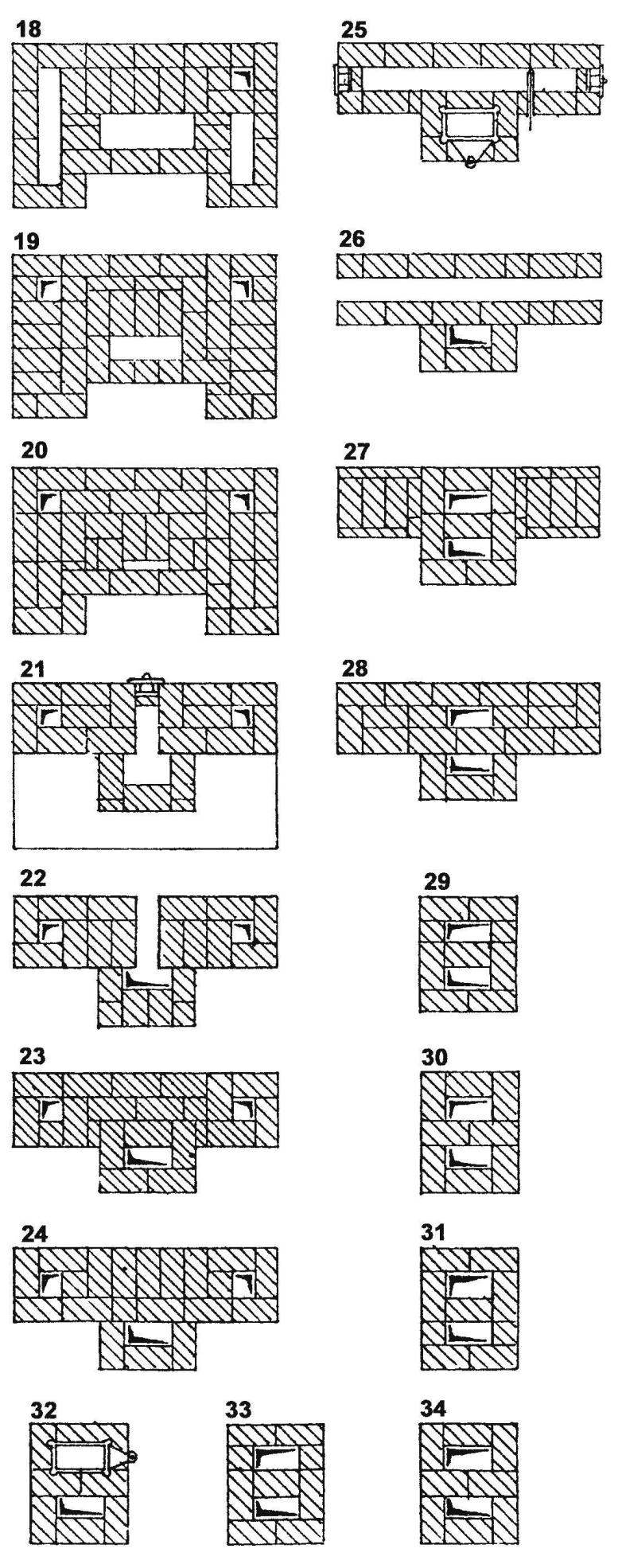
Fig. 3. Masonry series (the lining):
1 — 17 (34)
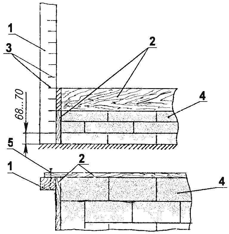
Fig. 4. Laying in the rolling shuttering:
1 — front (wooden beams 70×70, 4 pieces); 2 — formwork at the height of the first rows of masonry (edged, 140×40); 3 risks; 4 — rows of masonry; 5 — a fixation element (nail)
If desired, use an open flame on the stove oven 4 can be divorced fire, which corresponds to the fireplace of the “d” in the diagram. It is desirable to cover the combustion space from sparks doors from the grid 13, placed on one axis with the doors 12.
Joint or separate modes “b”, “b” for heating heat exchangers are selected depending on the quality of traction, the amount of fuel loading and thermal needs of the room.
Simultaneous operation in heating mode “b”, “C”, “d” corresponds to the maximum heating efficiency of the fireplace stove.
The Foundation
Oven refers to the heavy structures. Therefore, to serve reliably for a long time, you need to install it on a Foundation of rubble stone or concrete, buried in the ground 600 — 800 mm. the Foundation, the top of which is 2 rows of brickwork below floor level, must be increased by 50 — 100 mm than the dimensions of the furnace (see Fig.1).
The bottom of the pit perform on the level, then laid the first row of large stones or brick battle of the rubble, followed by pouring (after tamping) with cement slurry.
The main body of the Foundation is pouring the concrete into the formwork with rebar, and top of the base carefully levelled in the horizontal plane. After using a ruler and a square draws a contour of the furnace in which clay mortar are laid out two rows of bricks to floor level. At the same time on first row of masonry laid waterproofing 15 consisting of two layers of roofing material on bitumen mastic or roofing felt — on degtevoj.
Preparation of a clay solution
The quality of clay masonry ovens, be checked by comparing the envelop properties of the solution at different concentration of sand and clay. A certain proportion of these components in the future and is the basis for the preparation of a clay solution.
A quarter of a bucket of clay filled with water and thoroughly stirred to obtain a solution of medium thickness. If it completely envelops and is retained on a mixing blade, raised above the solution, forming a thick layer on its plane — so the clay is oily and requires the addition of sand. If the blade remain a separate clots, such clay is considered normal, requiring no additional sand. When the blade is covered with a thin layer of the solution — clay is considered to be the skinny: it requires the addition (in certain proportions) fat clay. The sand used to obtain the normal solution, pre-sifted through a sieve with a mesh size of 1,5×1,5 mm. the Prepared solution before masonry is filtered through a sieve with cells 3×3 mm.
The masonry stove
Getting to masonry stoves, ensure that its foundations are laid correctly and firmly, and place of masonry closed from rain.
First clutch of each set to produce a dry, without mortar, with a preliminary set of bricks. The bricks if necessary protesilaus and adjusted at the place of installation.
The masonry stoves need to thin seams of mortar thickness of not more than 3 to 5 mm, with bandaging of seams of the subsequent number — to enhance the entire design and save the gas density of the furnace. The solution should easily be squeezed out from under bricks from a light push with the hand.
Masonry critical parts furnace firebox and dymooborotov — should be made as follows: while the distribution of the solution with a hand on the bed laying well be felt unwanted impurities, stones, lumps that are removed.
Without prior dry pickup can be masonry with a trowel in places of continuous rows where the furnace array has a greater thickness, without dymooborotov—for example, at the base of the furnace. It is not recommended to use bricks with a flattened surface for masonry flue channels, as they can microsites. The ceiling smoke channels should make bricks without cracking, durable for a break.
During operation, monitor the grouting mortar. Each number lined it is necessary to check for levelness, Squareness, plumbness of walls and corners of the entire brickwork of the furnace. It is better to use the formwork, containing four vertical racks that are installed on the coordinates of the external corners of the structure, furnace coated after 68 — 70 mm risk sharing series (Fig.4).
The inner surface of the furnace and flues every 3 to 4 rows of masonry should be carefully prosperity — wipe with wet cloth to remove residue from the extruded solution and ensure the smoothness of the surfaces, which in turn positively affects the quality of thrust during operation of the stove.
It is impossible to coat the inside of the flue channels a clay solution: it will flake off in use and clog the channels that will reduce traction.
The first and second rows (Fig.H) give the mutual ligation of vertical joints. To save the outside number (not shown in the diagram) are laid out from a brick and the middle is filled broken.
In the third row is laid with its bottom part are chamfered with inclined front brick: this will facilitate the shoveling of ash.
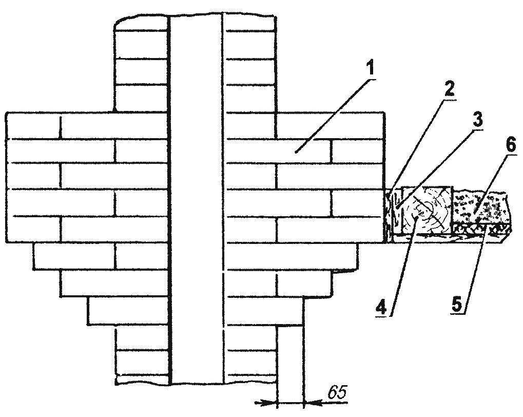
On the fourth row are installed, clean the bottom of the bypass channels of the heat exchanger and strengthens the door blew. Cleaning may be a simple hole, lay exposed brick. In this hole you can insert the cleanout door but it is better — frame with doors-boxes from a roofing steel (Fig.5). Frame performed with the fixing position of frame in the channel (with the help of mortar and brick trambovki). Box with handle must snugly fit in the frame, and before installing it on a clay solution are laid the bricks. The joints between the box and frame is also smeared with a clay solution that is restored after each cleaning.
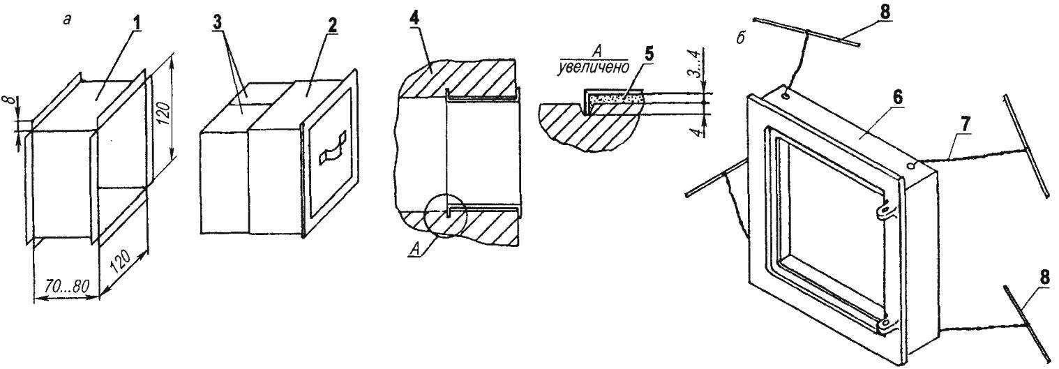
Fig. 5. Furnace mount devices (a—cleaning;—frame fire doors):
1 — frame cleaning (steel sheet s1,5); 2 — door in the form of a box (steel sheet s1,5); 3 — brick liners; 4 — main walls; 5 — the solution (clay); 6 — frame of fire doors; 7 — wiring (wire Ø5); 8 — cage terminals (wire Ø4—Ø5)
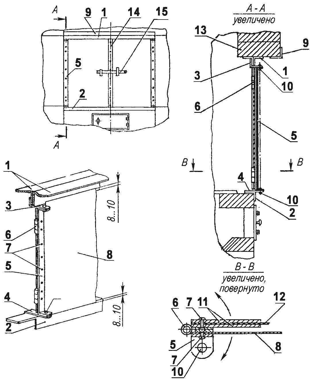
Fig. 6. Installation of doors cooking chamber:
1 — top floor Windows; 2 — lower frame area; 3 — axis bracket upper (corner); 4 — lower axis bracket; 5 — a clip-door; 6 — loop net rotation of the door; 7 studs; 8 — leaf (solid) door; 9 — upper frame area; 10 — siderca; 11 — trim mesh; 12 — grid; 13 —brick ceiling; 14 — vertical trim right door; 15 — a bolt
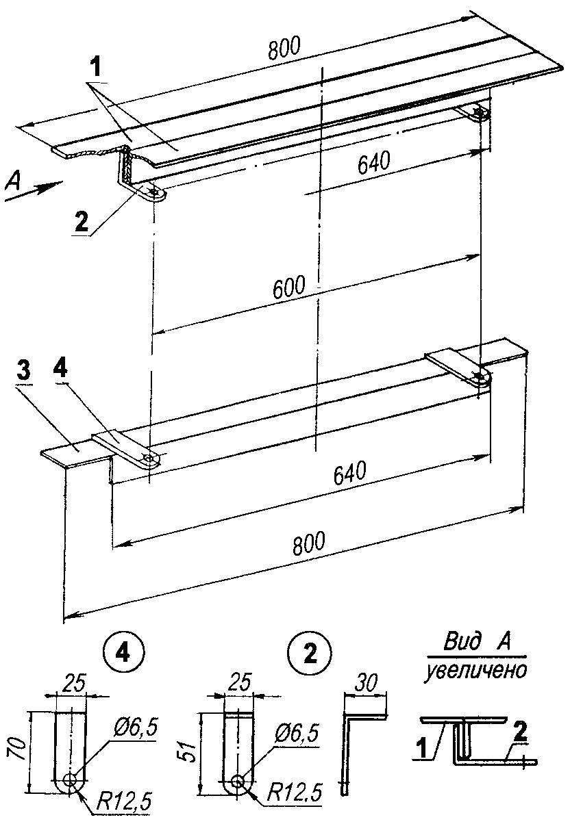
Fig. 7. The window frame of the cooking chamber:
1 — top covering (steel corner 4x35x35); 2 — upper bracket axis doors (steel, strip 5×25); 3 — lower frame angle (steel corner 4x35x35); 4 — bottom bracket axle doors (steel, strip 5×25)
Before installing the blower door in the corner holes of its frame strengthened lobes of retinue wire length 150 — 200 mm, the ends of which are attached pieces of 4 — 5 mm wire with a length of 100 mm, sealed between the rows of masonry.
Fifth row is the overlap of the bricks above podduvalom-sized grates, with trambovkoj bricks for steel strip 5×25 mm section length 300 — 350 mm, which is the front cross-support grate.
Sixth next overlap the lower guide channels of the flue heat exchangers with the formation of vertical components of the channels. Set the fire grate in the TES side and front of the adjacent bricks at an angle of 45°. The gaps between the bricks and the bars should be not less than 5 mm.
Bars put without mortar; deaf cracks filled with sand.
The seventh next to strengthening fire door, similar to the installation of the blower door (with the lobes of the wires). Before installing the frame is wrapped in one layer of asbestos cord or tape with a thickness of 5 mm. and the sixth row, is the further expansion of the furnace at an angle of 45° at the side boards of adjacent bricks.
Eighth near ends of the angular extension of the furnace. Installed clean inlet flues of heat exchangers.
On the ninth row are exhaust ducts of the furnace and covered with a brick in a castle a gap above the firedoor. To enhance the number above the firedoor sets the frame 2 (Fig.6) of the angular steel section mm. 35x35x3 Pre-welded to it two brackets with holes for the pivot doors of the cooking chamber.
On the tenth row on a thin layer of a clay solution is placed chimney stove size 410×710 mm, which can be replaced by an integral plate, preferably with one large or two burner holes. At a laying of this number of the side adjacent to the stove, brick stesyvajut the size of the plate and the brick, overlapping the channel is placed on an edge. The cracks are closed with suitable steel corners.
The eleventh, twelfth, thirteenth and fourteenth rows are similar, but are performed with ligation of masonry joints.
At the fifteenth row of the valve regulating the smoke channel of the left heat exchanger. Is the overlap a quarter of the brick back wall of the furnace chamber.
The sixteenth and seventeenth series continues the stepped overlap of the rear wall of the combustion chamber with the bandaging of seams of a laying.
On the seventeenth row is set by-pass valve of ignition furnace (see Fig.1, POS.11) with the formation of the upper by-pass flues and heat exchangers. From an angular steel section not less than 35x35x3 mm is the overlap 1 (Fig.6) of the combustion space of the fireplace and set the device fastening the upper hinge of the door of the cooking chamber. To strengthen and increase the support area for bricks overlap is formed from metal parts with the formation of the T-shaped profile, which are welded to the brackets 3 with the holes under the rotating axis of the door camera. When installing a T-shaped upper slab with brackets it is necessary to provide alignment holes under the axis of the door of the cooking chamber with holes in the brackets ceiling furnace space.
Device raspushki slouchy bricks in the area of the ceiling:
1 — numbers of a laying pipe, 2 — felt strip, 3 — beam, 4 — beam ceiling, 5 — layer mines, 6 — backfilling
Masonry oven (after the seventeenth series)
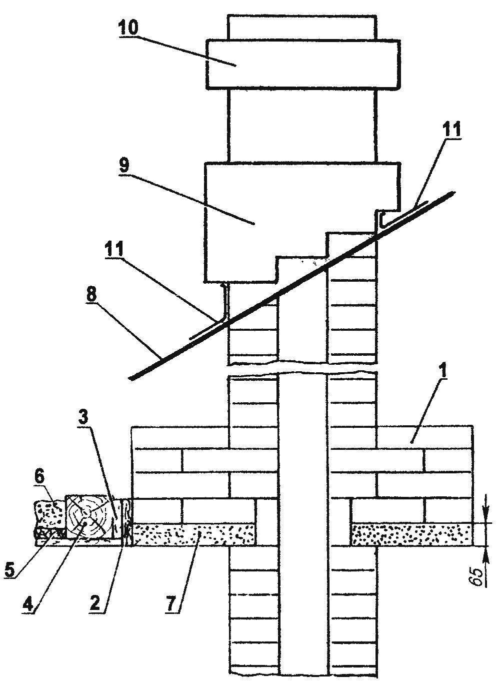
Cutting pipe on a concrete slab:
1 — masonry cutting, 2 — felt insulation, 3 — beam, 4 — beam ceiling, 5 — layer clay, 6 — backfilling; 7 — reinforced concrete slab; 8 is the slope of the roof. 9 — overlap bricks (otter); 10 — the top of the tube, 11 — skirt (roofing iron)
In the eighteenth number of the formation of the slope of the rear wall of the combustion chamber — when the overlap of a quarter of brick and with the same overlap of the side walls, narrowing the outlet of the chamber.
During the nineteenth and twentieth series completes the clamping of the combustion space of the fireplace of the stove (with the same overlap of the bricks, as in the previous rows), with the formation of the smoke of the tooth Such a device the output of the camera is designed to build soot deposits and prevent the overturning of the thrust due to the potential lowering at the rear, the colder the wall of the chimney gases are cooled when they approach the plane of smoke “tooth” to the outlet of the combustion chamber are picked up more hot gas flow and are carried through a flue.
Twenty-first row, on the horizontal plane smoke “tooth” is formed by the inner channel and is installed cleaning a chimney flue to remove soot deposits.
At the twenty-second row is completed, the output section of chimney flue through the inlet, and a quarter of the planks at an angle of 45° two socket bricks an Inclined plane during operation of the furnace reflects the sparks flying on the plane of fire “tooth” that prevents their exit through the chimney.
Twenty-third and twenty-fourth rows are similar, with the bandaging of seams overlapped fireplace cleanout channel At the twenty-fifth row is laid flip the smoke channel, connecting the heat exchangers are clean and the fireplace flue damper and the regulating throttle the right of the heat exchanger.
On the twenty-sixth through twenty-eighth series is completed laying the main body of the furnace body with the formation of the exit section of the furnace chimney.
On the twenty-ninth to thirty-fourth series of runs the initial masonry chimney with two separate channels of the chimney and the fireplace chimney. Thus on the thirty-second row set locking damper furnace flue.
This clutch pipe is carried up to the ceiling Then, not reaching three to four rows before the start of the attic floor is fuzz — uniform overlap bricks to obtain a wall in half brick at the level of slabs; masonry in this form continues to the height of four rows above the attic subfloor.
Cutting (fuzz) will be easier if you use the concrete slab produced in the mold along the pipe laying (at ceiling level) then it is masonry cutting. Initial covered by the number plate, is laid out on the edge, and then supplemented by the perimeter of cutting the bricks laid flat on a prepared slab (see Fig.).
Beams, wooden floors and decking adjacent to the cutting, be sure to isolate the two layers of asbestos or the felt soaked in a clay solution.
To the roof pipe is laid in clay mortar, and above the cement At the exit point of the barrel of the pipe above the roof running the otter-the overlap of bricks, prevents the penetration of rain through the gap between the pipe and the roof.
Initial drying furnace is made in a natural way, with open doors and dampers for 10 to 12 days Further drying is effected by burning a small amount of dry fuel three to four times a day. Drying is considered complete, if the outer surface of the stove will not remain moist places, and the damper traces of moisture.
After drying, the surface of the oven rubbed with a brick and Belitsa.
Before operating the furnace is hung the door of the cooking chamber, combined with a mesh fireplace doors. The mesh is enclosed by the strips of iron on the height of the internal window size and is mounted on two hinges on each side on the solid door that overlaps the frame corners at 10 mm.
After completion of masonry work, before drying, on the floor in front of the firebox is fixed predtopochnyj sheet (1400×700 mm), under which (between the sheet and the floor covering) is enclosed by an asbestos cloth or felt impregnated with clay mortar.
For the manufacture of furnace pipe height 6 .7 m will be required; red bricks — 1000 pieces; clay with sand — 1 m3; furnace door — 250×130 mm; ash-pit door — 130×130 mm, two smoke valve— 130×240 mm, the other three exhaust valves — 130×130 mm; steel strip — 25x5x400 mm, grate — 200×300 mm; cast iron stove — 410×710 mm; angle steel 35x35x4x800 mm — 3 PCs; predtopochnyj sheet metal — 1400×700 mm.
For reliable and safe operation of furnace is best to heat with wood If you want to use a coal furnace furnace is laid with refractory bricks or poteryatsya cast-iron plates. In this case, for removal of accumulated gases after closing of the furnace chimney valve, it must make a hole with a diameter of 10. .15 mm.
The furnace design, in addition to the normal operations of cooking to prepare it as an open fire, grilling or barbecue, smoke fish.
If the layout of the house separate room for kitchen hearth furnace can be rotated 180° and the window of the cooking chamber will be located between the eighth and fifteenth rows of masonry, which creates additional convenience – like the ability supply of food in the room through the fireplace window.
During cooking of the combustion chamber window is closed by double doors, and if the furnace is in the fireplace mode the flap is closed the window of the cooking chamber.
If the furnace in the back to Supplement the cooking chamber with an inclined hearth and a bench you can get the improved version on the model of the Russian stove in the use of gas flow it will even bake bread.
This design multifunctional oven may appeal to fans of exotic kiln installations, when all positive and negative qualities of the combination option can be considered.
In the design of the furnace was assumed a complete reconciliation of the firebox of the furnace and the fireplace But then the chimney plate should be hinged plates, which is a certain difficulty, and the front wall of the furnace in the fireplace mode completely open (to improve the thermal performance of the fireplace and the normal functioning of the chimney thrust).
If the height of the building allows us to produce pipes is not below 7 meters — operation of kamiloiki can be produced with one chimney flue, and also to simplify the design of the furnace, if the level of the thirty-fourth series to make entering the furnace flue in the fireplace. This design, in turn, will facilitate the firing furnace in a cold hot air through the corresponding valve.
V. ZELENOV, Voronezh
Recommend to read
 THE BTR – 60PB
Scale model 1:25. By order of the Minister of defence of the USSR from 29.06.1964 the Soviet Army was adopted by the BTR-60PB, created by the design Bureau of Gas under the leadership... CHAIR FIDGETS
There are restless people, they are literally turning on the seats, even when doing serious work. Why not meet them and not make the chair so that he could turn? The chair...
