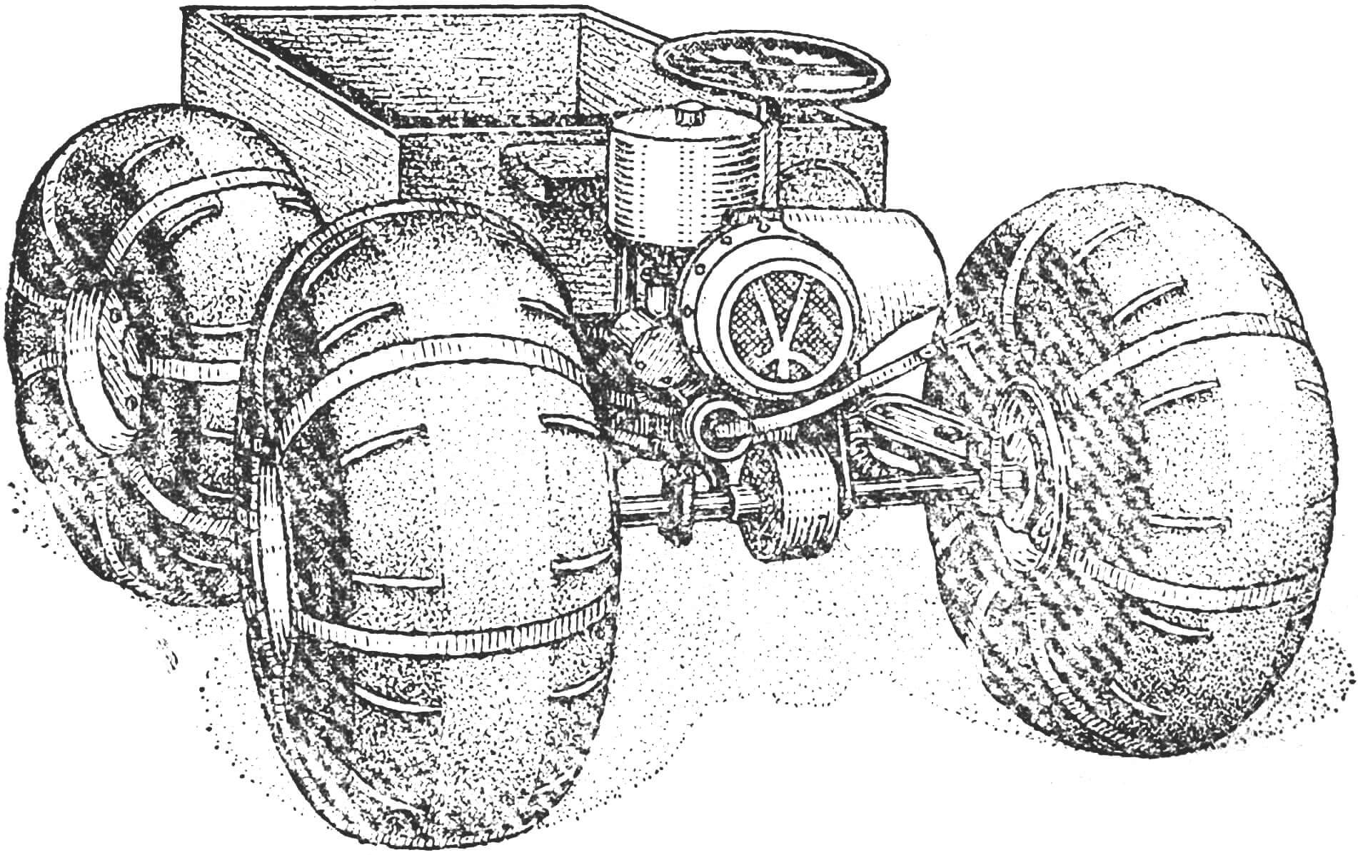
The all-terrain vehicle is made according to a design that has proven itself well on the Kirovets tractor. It has the same “breakable” frame and drive on both axles. What does this give? Firstly, cross-country ability. The frame, constantly bending, seems to follow the terrain. All four drive wheels are constantly in contact with the surface. This eliminates overloading of individual wheels and their slipping on uneven ground. Secondly, maneuverability. The articulated frame reacts sensitively to even minor steering deviations and allows you to turn almost on the spot. Thirdly, constructive simplicity. In this scheme, you can use exactly the same front and rear axles. The engine mount is also simple.
The frame consists of two main parts connected in the middle by a hinge with a vertical axis of rotation. Its front part is a rigid welded assembly on which the axle, engine, fuel tank, control pedals and driver’s seat are installed. The left supporting arc of the frame also serves as a muffler.
The hinge with a vertical axis of rotation consists of two forks connected by powerful fingers. The pins are bolted to the rear fork lugs, and the front fork pivots around them in thrust and needle bearings.
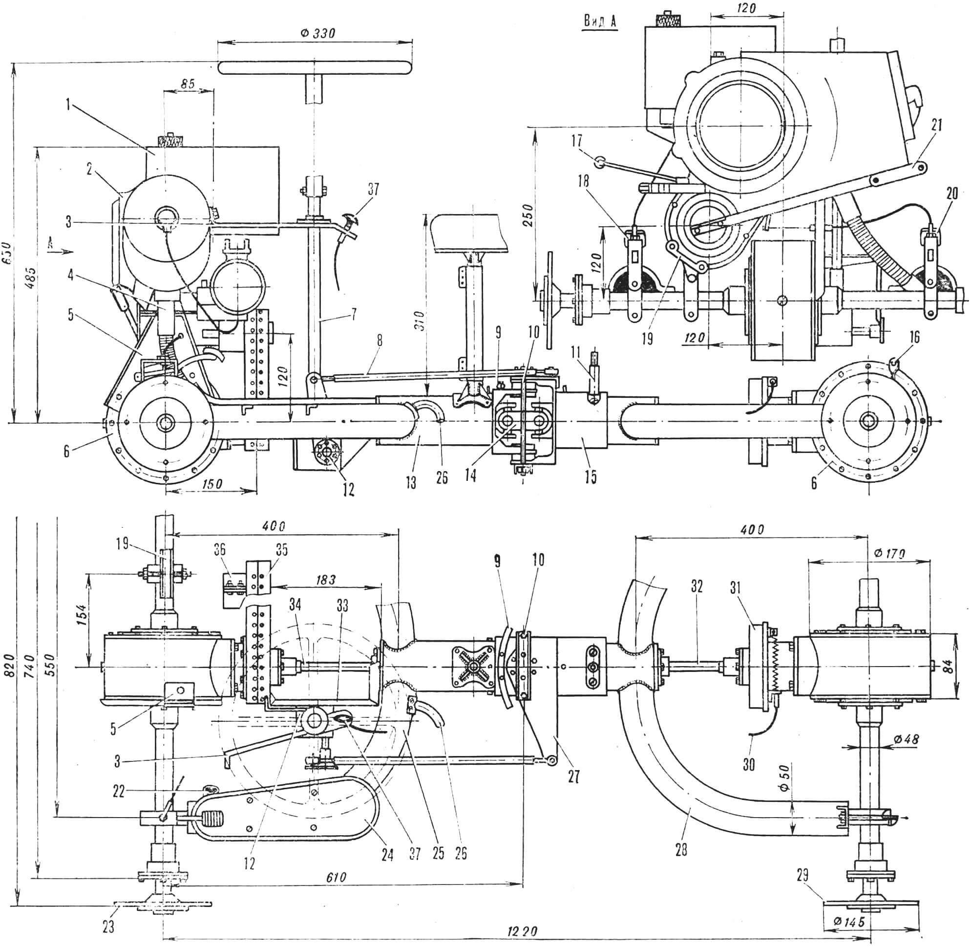
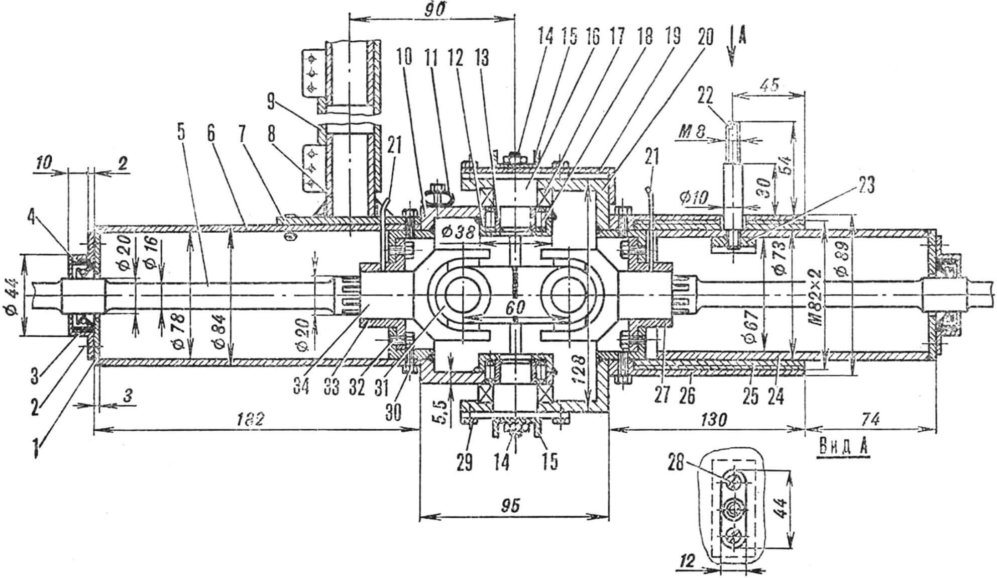
1 – fuel tank, 2 – engine, 3 – steering column mounting bracket, 4 – exhaust pipe, 5 – central engine mounting bracket, 6 – differential housings, 7 – steering column, 8 – tie rod, 9, 10 – angle limiters ” “fracture” of the frame, 11 – limiter-bolt for fastening the body. 12 — steering worm drive, 13 — front propeller shaft housing, 14 — connecting link, 15 — rear propeller shaft housing, 16 — body mounting loop, 17 — gear shift lever, 18 — gas pedal, 19 — lower engine mounting bracket, 20 — clutch pedal, 21 — kickstarter, 22 — muffler inlet pipe, 23, 29 — axle shaft flanges, 24 — step, 25 — frame support arch (muffler), 26 — exhaust pipe, 27 — steering rocker, 28 — frame support arch, 30 — brake cable, 31 — brake drum, 32 — rear driveshaft, 33 — steering gear bracket, 34 — front driveshaft, 35 — chain drive housing, 36 — rear engine mounting bracket, 37 — brake handle.
To prevent the wheels from rubbing against each other when the frame “breaks” around the vertical axis, the hinge has limiters installed respectively on the front and rear forks: a slightly bent and flattened tube for rigidity and two studs at the ends of the channel brackets. The rear part of the frame – the bridge, brake and removable body are attached to it – is movable, its hinge is with a horizontal axis of rotation. But it is designed somewhat differently: a fixed casing with an internal thread, into which a bronze bushing is screwed, is riveted to the rear fork. It serves as a sliding bearing for the movable casing of the rear part of the frame.
This casing is held in the sleeve by a pin screwed into the reinforcing lining. It is also the limiter of the angle of “break” of the frame relative to the longitudinal axis of the all-terrain vehicle. The size of the angle depends on the length of the groove cut into the fixed casing and sleeve.
The VP-150M engine is installed transversely so that it takes up less space, and the air-cooling fan has the most favorable operating conditions.
The mounting brackets are located as follows: the central and most powerful one is on the differential casing, under the engine cylinder, the lower one is on the right axle beam, under the crankcase, and the rear one is on the chain drive casing.
A metal fuel tank with a capacity of 5.5 liters is attached to the engine crankcase; Fuel enters the carburetor by gravity.
The controls are located on the front axle beams: the clutch pedal is on the left, the gas pedal is on the right. For the driver’s convenience, footrests are installed next to the pedals.
Gears are switched by hand using a lever with a ball at the end, welded to the gear sector.
The engine is started by a kickstarter with a crank instead of a pedal.
Exhaust gases from the cylinder through a corrugated pipe enter the left supporting pipe of the frame as a muffler and exit from the exhaust pipe under the seat.
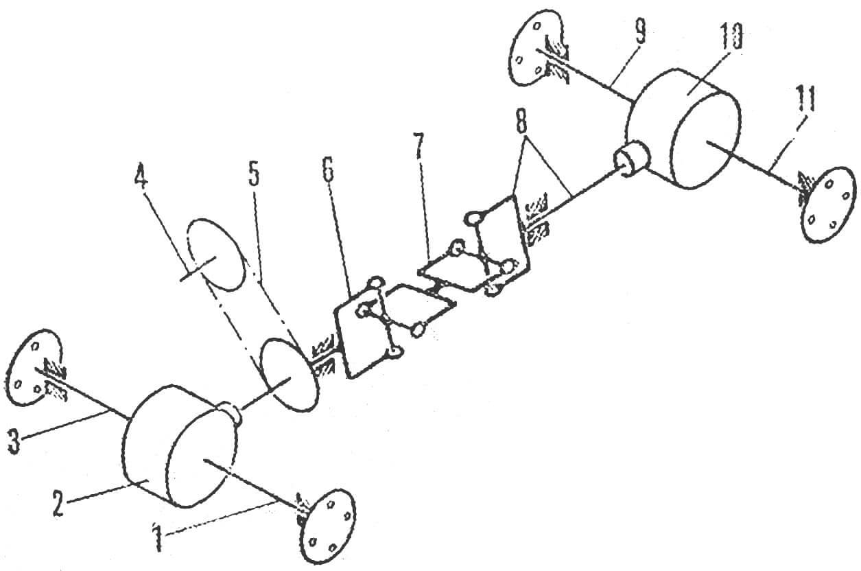
1,3 — front axle axle shafts, 2, 10 — differentials, 4 — engine output shaft, 5 — chain drive, 3 — front propeller shaft, 7 — connecting link, 8 — rear propeller shaft, 9, 11 — rear axle axle shafts.
The transmission of the all-terrain vehicle is symmetrical relative to the vertical axis of the “break” of the frame. The torque from the engine is transmitted by a chain to the cardan shafts, and from them through bevel gears and differentials to the axle axles.
Cardan shafts are machined from rod. In the middle they have necks for sealing cuffs, and at the ends there are slots. Cardan shafts with crosspieces (including those for the connecting link) were taken from the Ural motorcycle. They rotate in bronze bushings, which are lubricated from time to time through thin oil nipple tubes brought out.
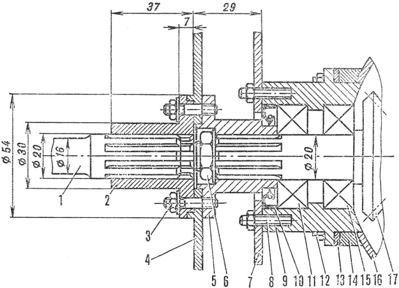
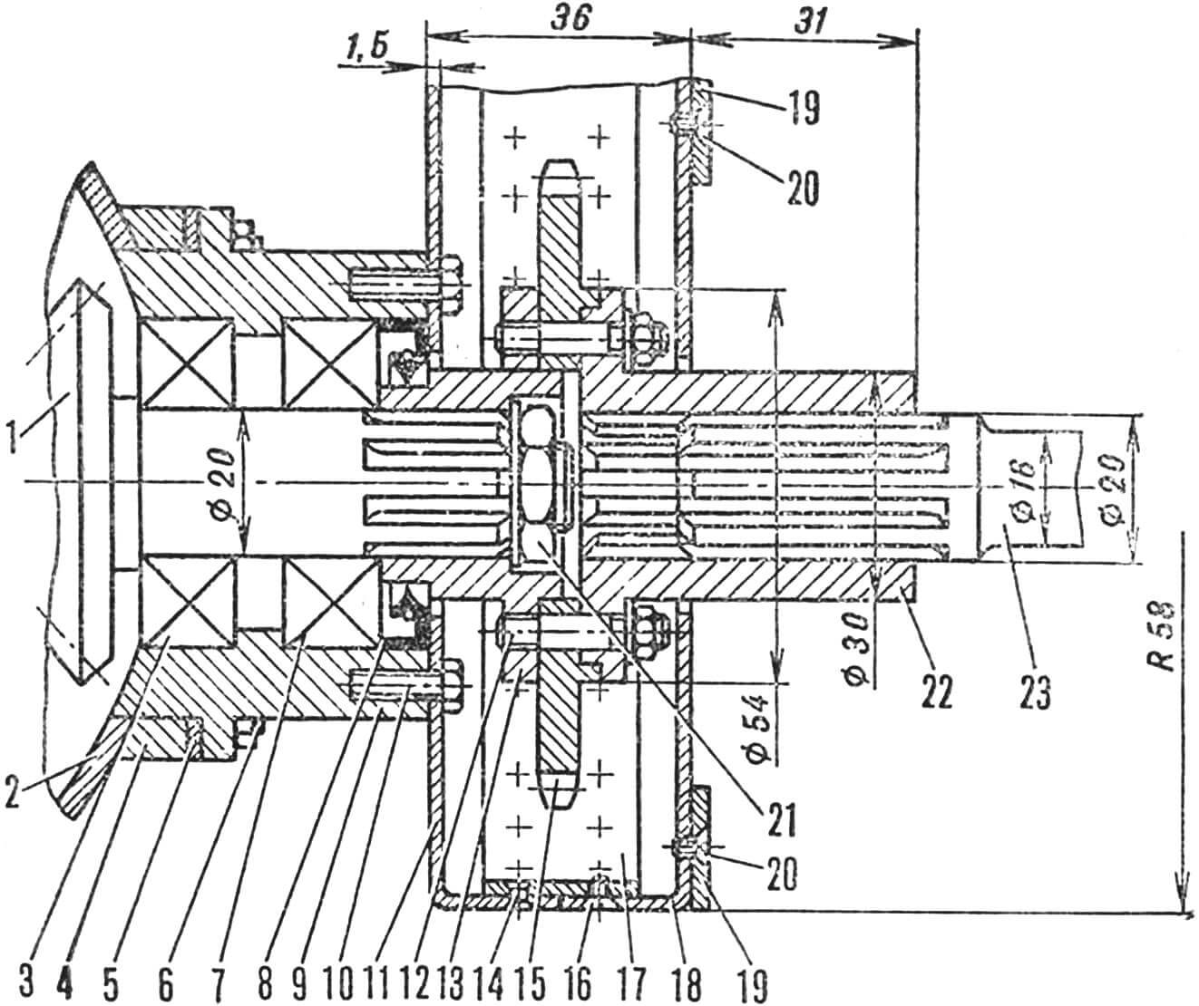
1 – rear propeller shaft, 2 – outer flange, 3, 8, 12 – M6 studs, 4 – brake drum, 5 – inner flange, 6 – nut M14X1.5, 7 – brake disc, 9 – bearing housing, 10 – cuff, 11, 15 — tapered roller bearings, 13 — adjusting gasket, 14 — spacer, 16 — differential casing,
17 – bevel gear drive.
With external splines, the propeller shafts fit into the outer flanges that connect them to the shanks of the bevel gears. The rear shaft is equipped with a brake from the Vyatka scooter: the brake disc is attached to the bearing housing with pins, and the drum is attached to the flanges. The control cable from the disk is routed to the steering column.
1 — bevel gear drive, 2 — differential casing, 3, 7 — tapered roller bearings, 4 — spacer, 5 — adjusting shim, 6, 12 — M6 studs, 8 — cuff, 9 — bearing housing, 10 — M4 bolt, 11, 18 — casing halves, 13 — internal flange, 14 — rivet Ø 3 mm, 15 — driven sprocket, 16, 20 — M4 screws, 17 — lining, 19 — steering gear bracket hinges, 21 — nut М14Х1.5, 22 – outer flange, 23 – front driveshaft.
The axle differentials on the all-terrain vehicle are of a traditional design: with two satellite gears (from the Moskvich-412 car). The side gears are homemade, and the bevel gear is taken from a Ural motorcycle.
The cracker, unlike the Moskvich one, does not have a spherical surface facing the differential housing, but a cylindrical one, for simplicity.
1 — plug, 2 — M3 screw (4 pcs.), 3 — cuff body, 4 — cuff, 5 — front propeller shaft, 6 — front casing, 7 — trim, 8 — seat post, 9 — seat height adjuster, 10 – front fork, 11 – frame bend angle limiter tube, 12 – needle bearing housing, 13 – bushing, 14 – frame bend angle limiter pin, 15 – frame bend limiter pin brackets, 16 – bend pin axis » frame, 17 — thrust ball bearing, 18 — needle bearing, 19 — steering rocker, 20 — rear fork, 21 — oilers, 22 — body mounting limiter bolt, 23 — reinforcing lining, 24 — movable casing, 25, 27, 33 – bronze bushings-bearings, 26 – fixed casing, 28 – M5 screw (2 pcs.), 29 – M6 bolt for fastening the pin-axis (6 pcs.), 30 – M6 bolt (8 pcs.), 31 – connecting link, 32 — M6 bolt (4 pcs.), 34 — cardan.
Bridges are attached to the frame using bolts, liners and shims. Only on the rear axle are the bolts holding the body fastening hinges, and on the front axle are the gas and clutch pedal brackets.

1 — wheel flange, 2 — oil seal, 3 — cover, 4 — bearing housing, 5 — axle shaft bearing, 6 — cuff, 7 — retaining ring, 8 — axle beam, 9 — axle shaft, 10, 17 — differential housing flanges, 11 – cover, 12 – driven bevel gear, 13 – M8 tie rod, 14 – cotter, 15 – pinion of satellites, 16 – satellites, 18 – M8 pins, 19 – differential bearing. 20 — axle shaft bearing housing, 21 — gasket, 22 — differential housing halves, 23 — frame supporting arc, 24 — plug, 25 — adjusting spacer, 26 — liners, 27 — M8 coupling bolt, 28 — body mounting loop.
The steering consists of a removable steering wheel, a vertical column, a steering worm drive, two rockers and an adjustable rod. The drive ratio is 1:4, which allows you to “break” the frame not only while moving, but also when parked. The force from it is transmitted by a rod to the rocker attached to the fork of the rear part of the frame, and forces it. to deviate in one direction or another.
The wheels are also structurally simple and completely identical. The load-bearing element of each of them is an aluminum hub, to the ends of which discs made of the same material are screwed.
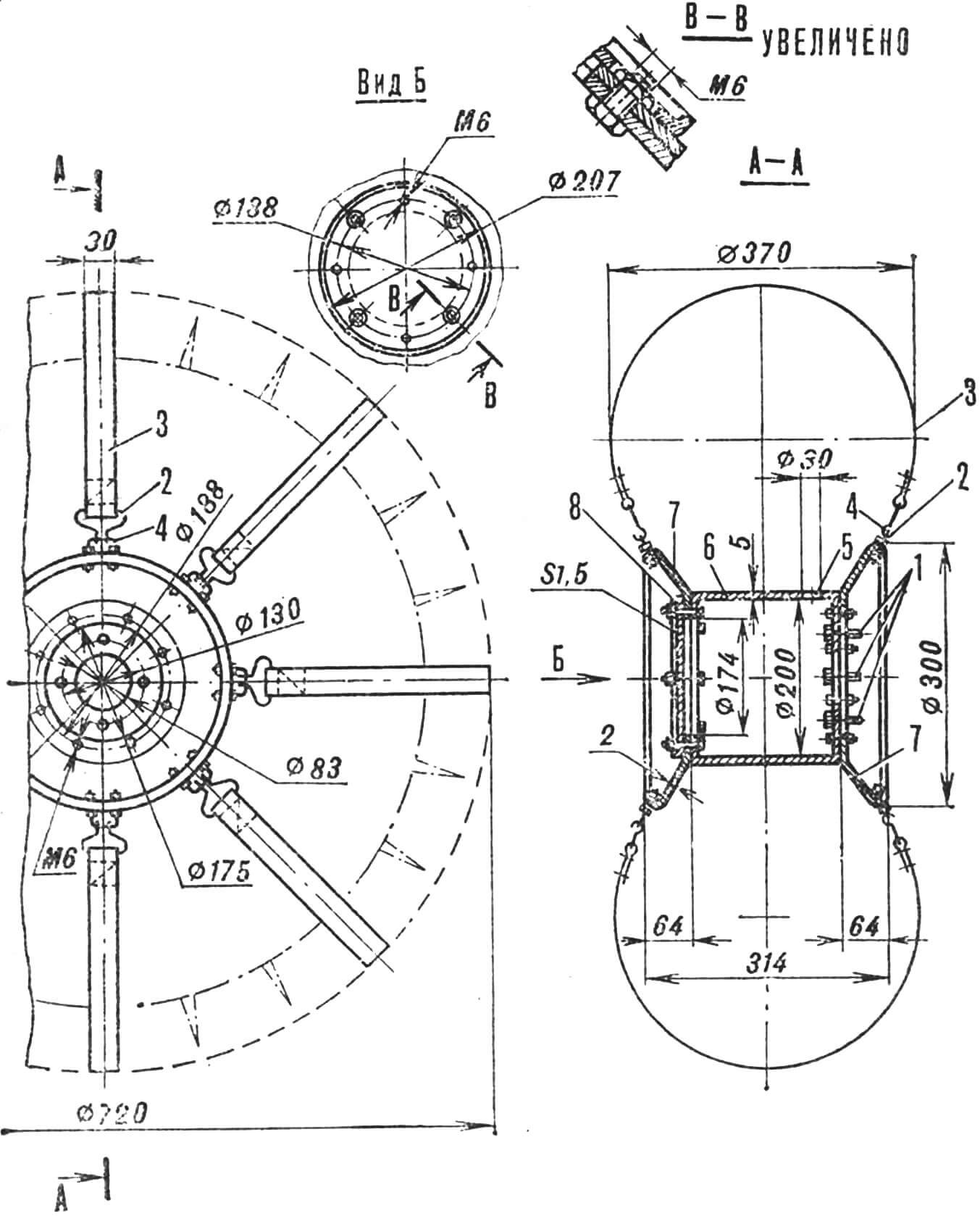
1 – M8 bolts for fastening to the axle flange, 2 – hook (wire Ø 3 mm), 3 – canvas belt, 4 – bracket (wire Ø 4 mm), 5 – hole for the valve, 6 – hub, 7 – disks, 8 – lid.
Eight canvas belts holding the tire are attached to the disks with wire hooks and staples – two chambers measuring 720X310 mm, nested one inside the other and protected by a canvas tape with tucks and lugs.
The outer end of the hub is covered with a cover, which protects its cavity from contamination, and the inner end is equipped with four bolts for attaching the wheel to the axle shaft flange.
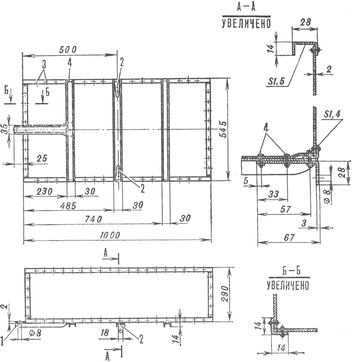
1 — front bracket, 2 — side brackets, 3 — rivets Ø 3 mm, 4 — M4 screws.
The body is assembled from a welded steel frame and fiberglass panels. The floor is given the necessary rigidity by three channels with brackets for installation on the all-terrain vehicle frame.
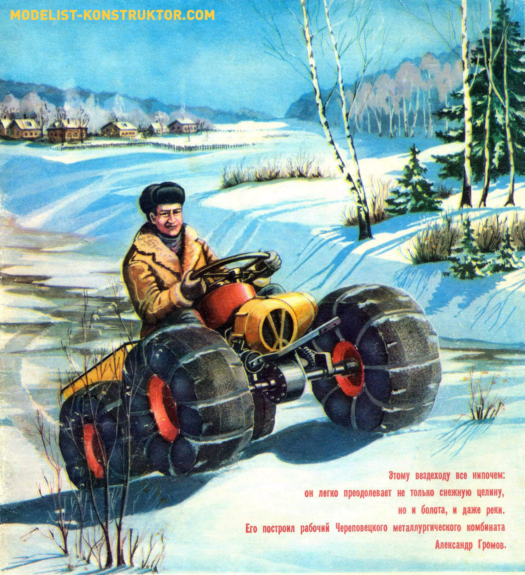
The weight of the body is only 6.5 kgf, but its dimensions are such that they allow an adult to sit without experiencing any particular inconvenience.
Maintenance of the all-terrain vehicle is practically minimal. It is enough to monitor the level of fuel in the tank, transmission oil in the axles and air pressure in the tires. Yes, occasionally lubricate the bronze bushings-bearings through oil nipples – that’s all.
A. GROMOV, A. TIMCHENKO
Recommend to read
 IMAGINE AND DO!
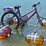
Plastic bottles of various capacities from drinks and even plumbing polyethylene pipes are an excellent material for building a wide variety of swimming equipment. And not only scale...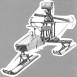 WOODEN SLED
Why not just get on the forest in the Arkhangelsk region wood! Prefer and lecturer in the school of the village Lamorna Oleg Dmitrievich Cheese. Teaching children the skills of working...
