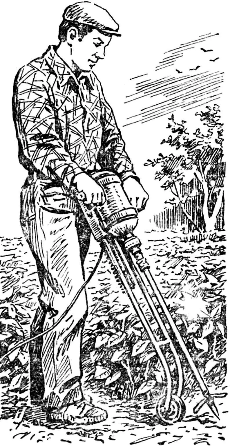
We have already talked about agricultural machinery that used an electric drill as an engine: mowers – rotary and with a cutting knife (see No. 9 for 1980 and No. 2 for 1981), a plow with electric traction (see No. 9 for 1981). Now we offer a new design on the same base – a soil loosener.
First, it is probably necessary to explain why I designed a mechanism, the main purpose of which is plowing, of exactly this design – in the form of an electric cultivator. Why I did not follow a more or less beaten path, using a walk-behind tractor with a plow. First of all, this was dictated by the small size of the area being processed and the high density of plantings – a walk-behind tractor simply cannot turn around here. Then I had to take into account the weight of the tool itself and the power of the drive, developing an average torque of only 3 kg. A teenager, a woman, and an elderly person can easily handle such a machine.
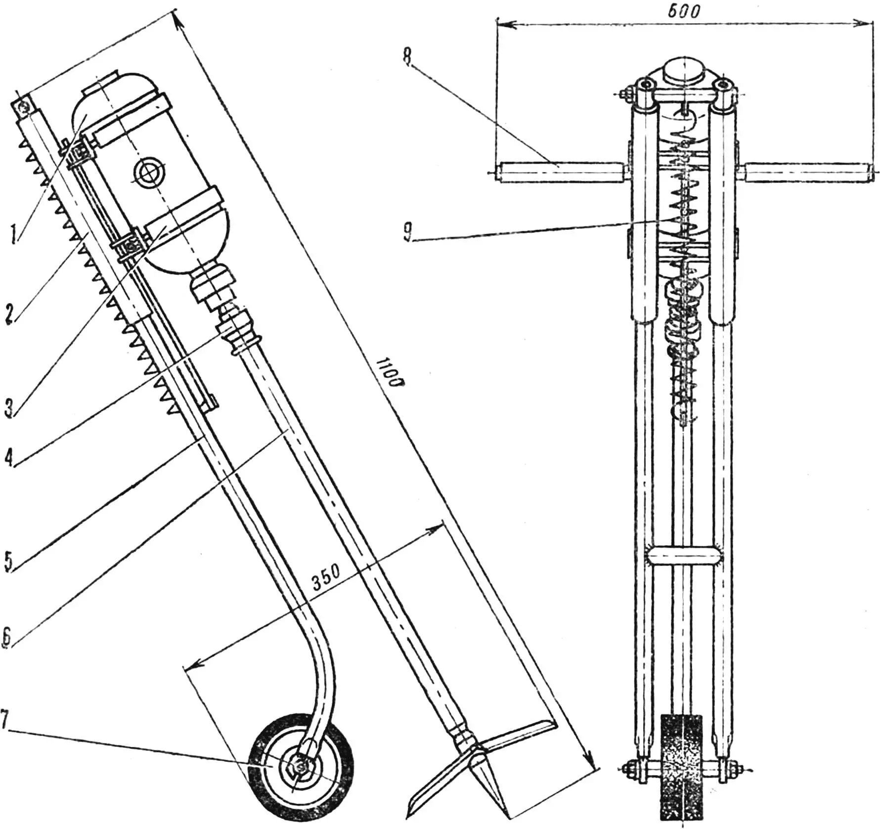
1 — drill, 2 — carriage, 3 — drill clamp, 4 — coupling sleeve, 5 — frame, 6 — working element, 7 — stop wheel, 8 — side handle, 9 — spring.
Now, after a good ten years of using the cultivator, we can list a number of its advantages. For example, it turned out that the soil is prepared in such a way that it does not require harrowing, while the upper fertile soil layer is not buried down, but remains on the surface. The guide cone goes about ten centimeters below the plowing – where it passes, moisture is retained better. You can work on steep slopes, in hotbeds and greenhouses, under fruit trees and around bushes, the degree of soil moisture also does not significantly affect the quality of the work. The entire vegetation period, inter-row cultivation can be carried out without damaging the roots of plants. And the last thing. This tool replaces a cultivator, harrow, hiller. The productivity of the mechanism at a plowing depth of 25 cm on difficult loamy soils is 70-80 m2 /h.
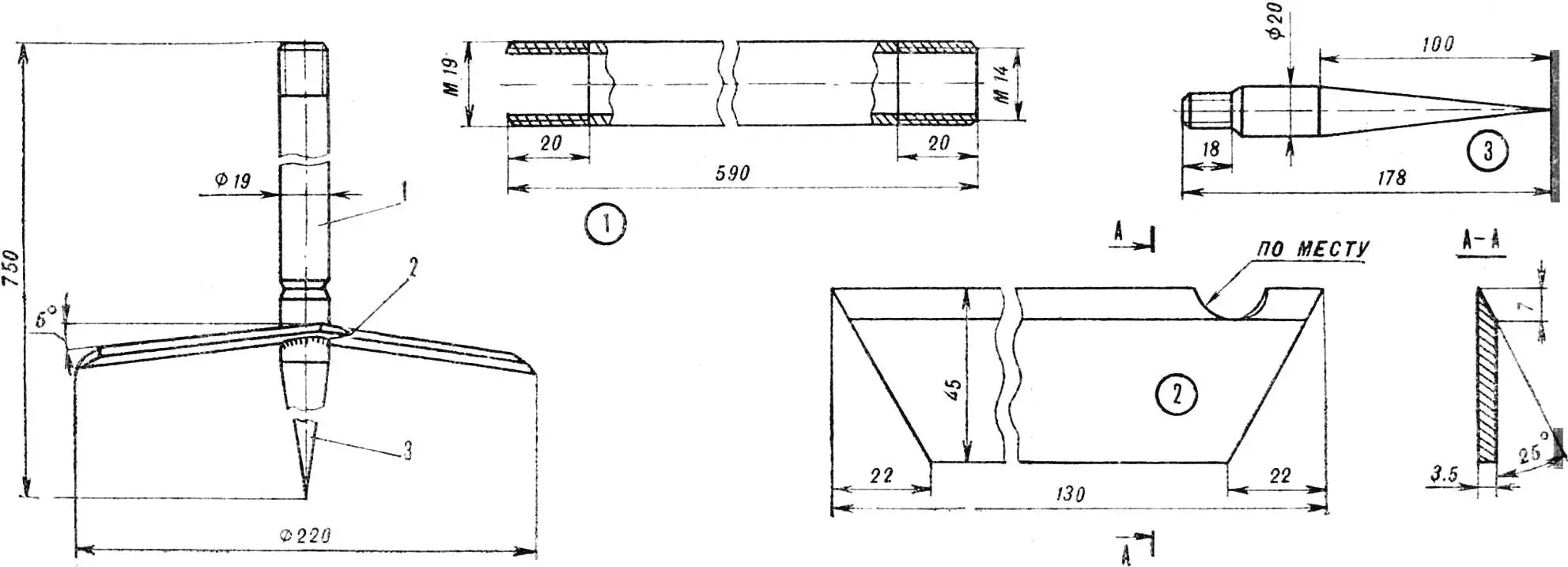
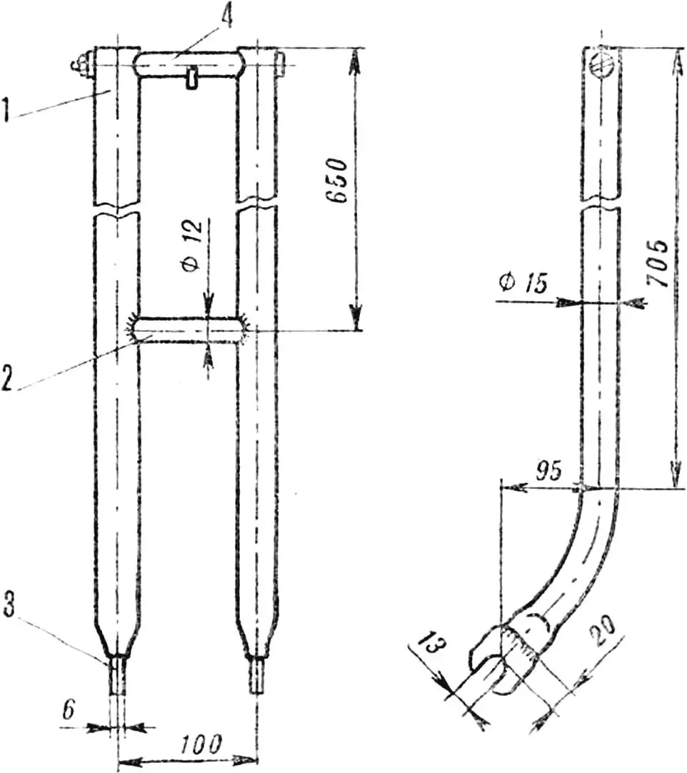
1 – knife bar, 2 – knife, 3 – tip.
The electric cultivator consists of a working element with a drive and a chassis-frame with a stop wheel. The drive-drill has two side handles. The cone coupling facilitates the replacement of the supporting rod, into the lower part of which the tip with welded knives is screwed. By the way, about the size of the knives: for heavy soils their Ø 220 mm, when working on lighter soils it can be increased.
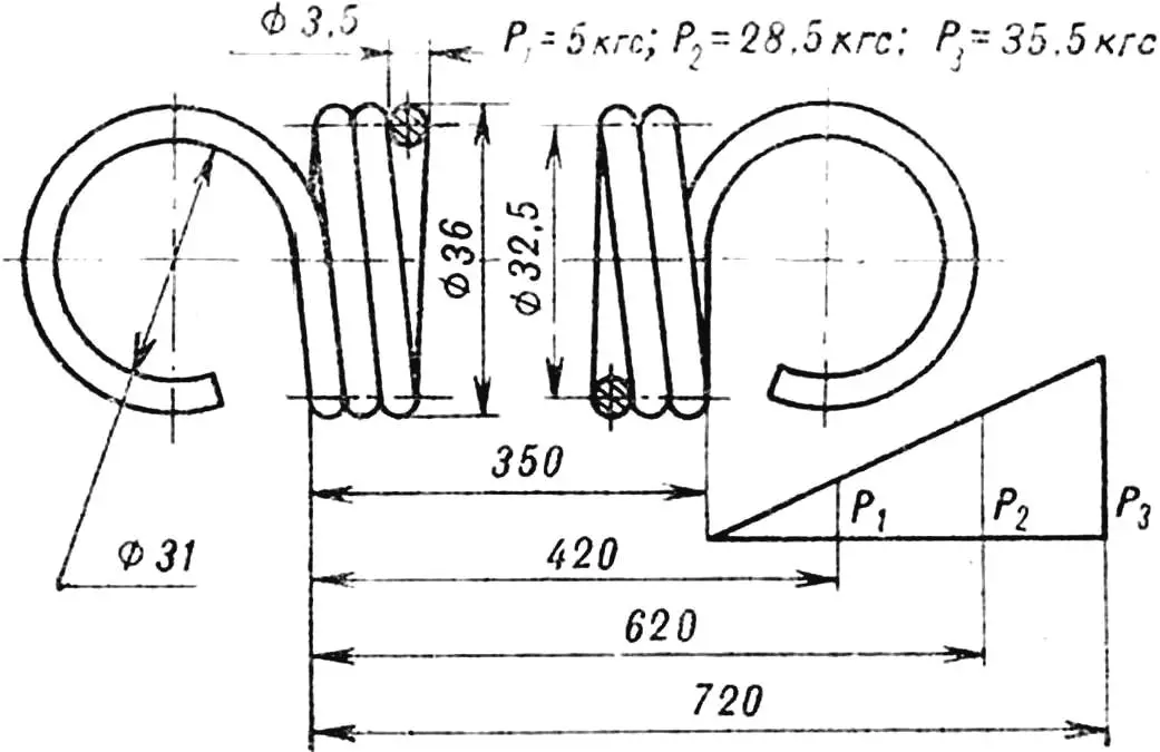
Number of working turns 95
Length of unfolded spring 9900 mm
HPC hardness 46…52
The frame had to be made in order not to keep the mechanism suspended all the time: the engine is fixed on its carriage. The latter can move up and down along the frame guide, but is constantly held by a compressed spring. Only when the plowman applies a certain amount of force, pressing on the drill handles, does it go down together with the carriage — the knives, rotating, gradually go deeper into the ground. When the force is reduced, the mechanism returns to its original position. In addition, the frame is equipped with a stop wheel with a ratchet, preventing the ripper from “rolling” from its place during operation.
Briefly about the main components and parts.
Carriage . Its skids (Ø 25.4 mm pipes) slide along the frame guides. Four transverse ribs of the stock with clamp lock plates are placed on the skids, with the help of which the drill is fixed to the stock. In the center of the ribs there are holes for the spring rod. The joints of all these parts are welded.
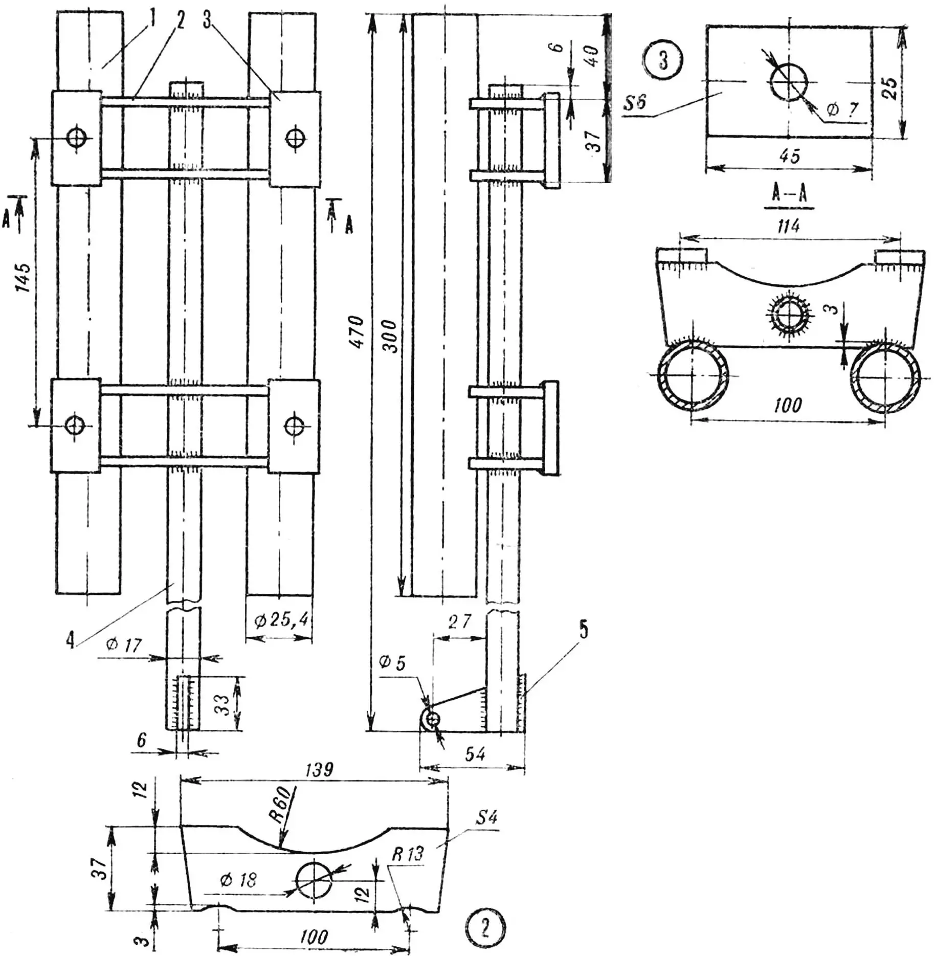
1 — carriage runner, 2 — stock rib, 3 — clamp lock plate, 4 — rod, 5 — spring earring.
Frame . Two guide tubes (Ø 15 mm) are connected at the top and in the middle by two crosspieces. During assembly, a return spring is stretched between the upper earring and the end of the carriage rod. The guides are flattened at the bottom, and the wheel axle journals are welded to them.
1 — guide, 2 — lower crossbar, 3 — wheel axle journal, 4 — upper crossbar with spring earring.
Clamp . Steel band measuring 3X20X310 mm. Threaded studs with M6 threads are welded to both ends. When assembling, the drill is wrapped with the band, the studs are inserted into the corresponding holes of the bed plates and tightened with nuts.
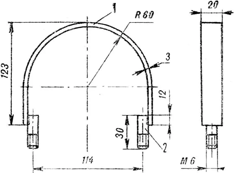
1 – tape, 2 – pin
Thrust wheel . Its 45 mm thick disk has a complex axial hole (part of its inner surface – a strip along the circumference – is made toothed for the ratchet). Here are located: a Ø 42 mm bearing, closed on the right side by a standard spring retainer ring, two side covers on M6X13 screws with felt packing rings, and a shaped axis. The ratchet leaf spring is attached to it. In addition, a thrust sleeve is put on. A bandage made of sheet rubber is glued to the disk.
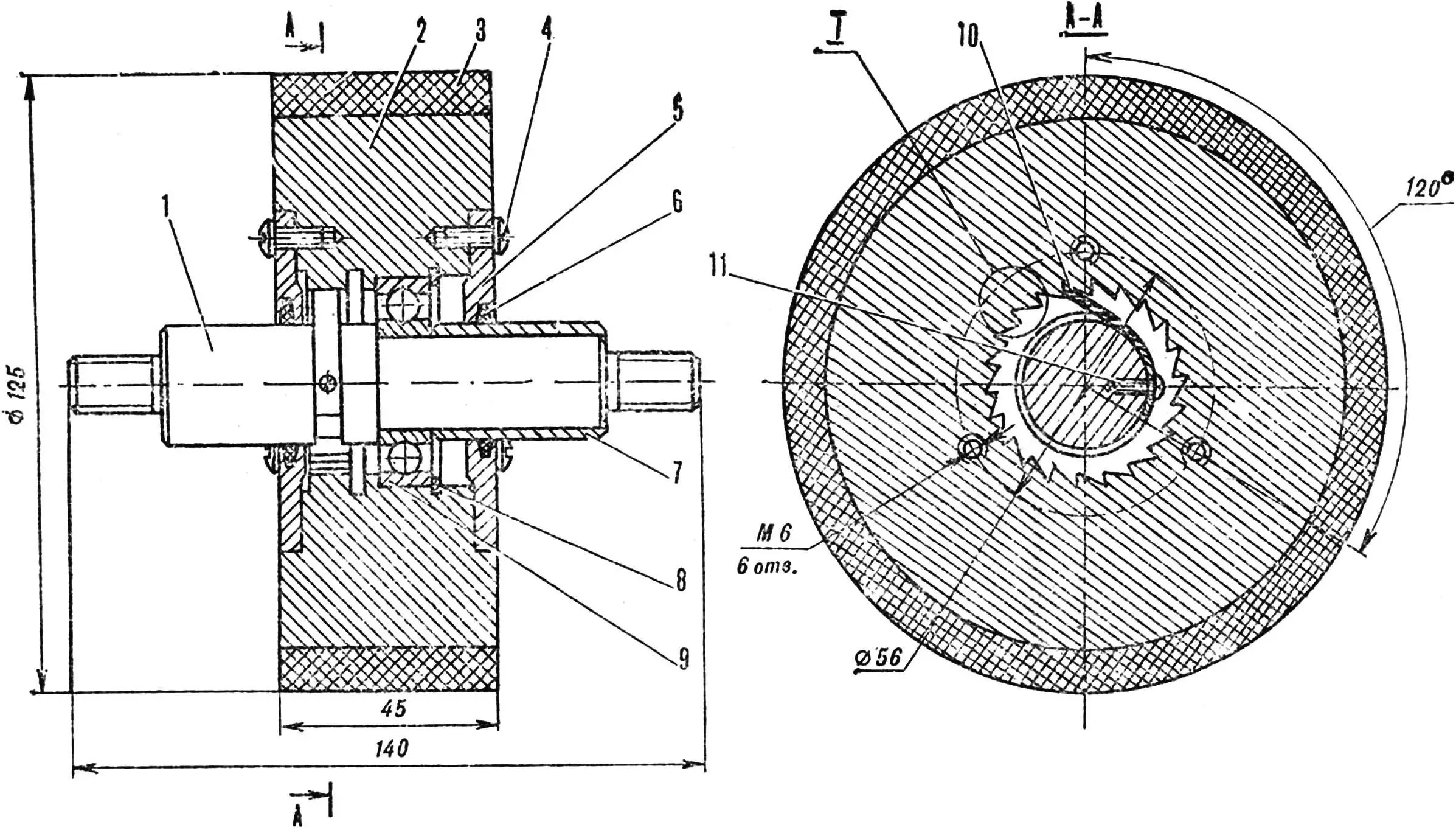
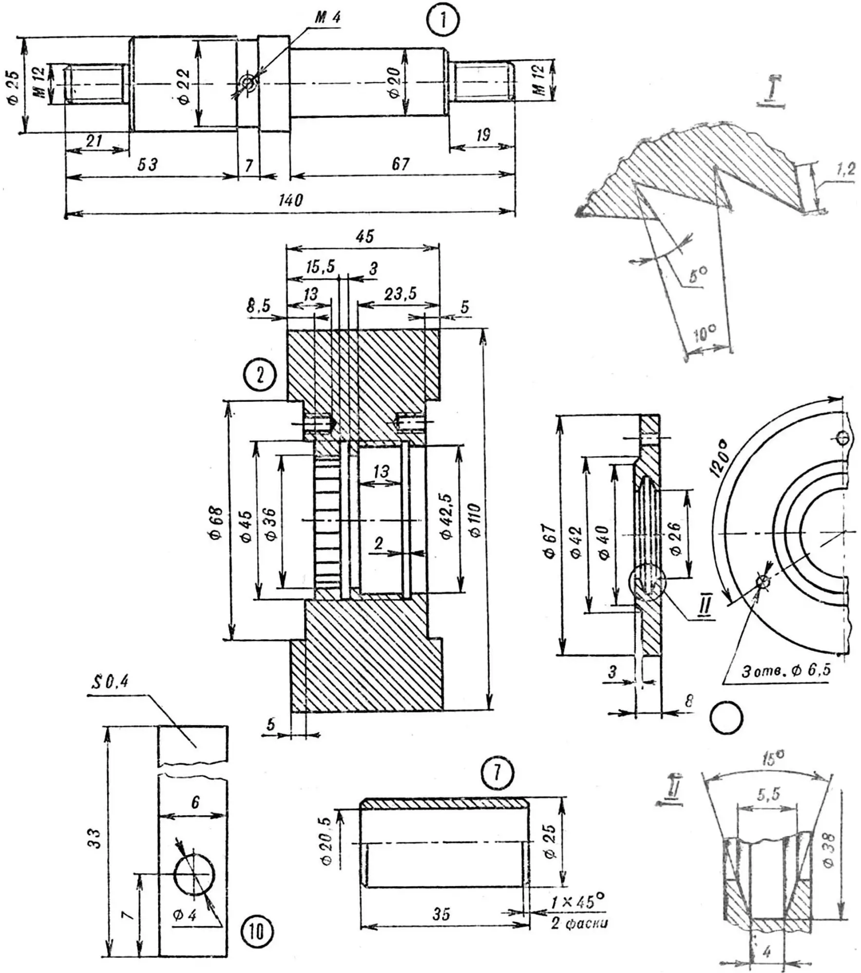
1 — axle, 2 — disk, 3 — bandage, 4 — screw M6X13, 5 — cover, 6 — sealing ring, 7 — bushing, 8 — spring retainer, 9 — bearing, 10 — spring, 11 — screw M4X11.
A. GLAZKOV
Recommend to read
 WITH A SHOVEL — CABBAGE
Old (and possibly new) shovel is easy to turn into unusual tool for cleaning.. cabbage. If it is the middle cut, as pucusana in the figure, and to sharpen, it will be possible in the... “VIRTULA” EVERY DENT
Elementary simple, ultra-reliable and very good running kachestva distinguished for the attention of young avtomodelistov development. This technique is extremely necessary for the...
