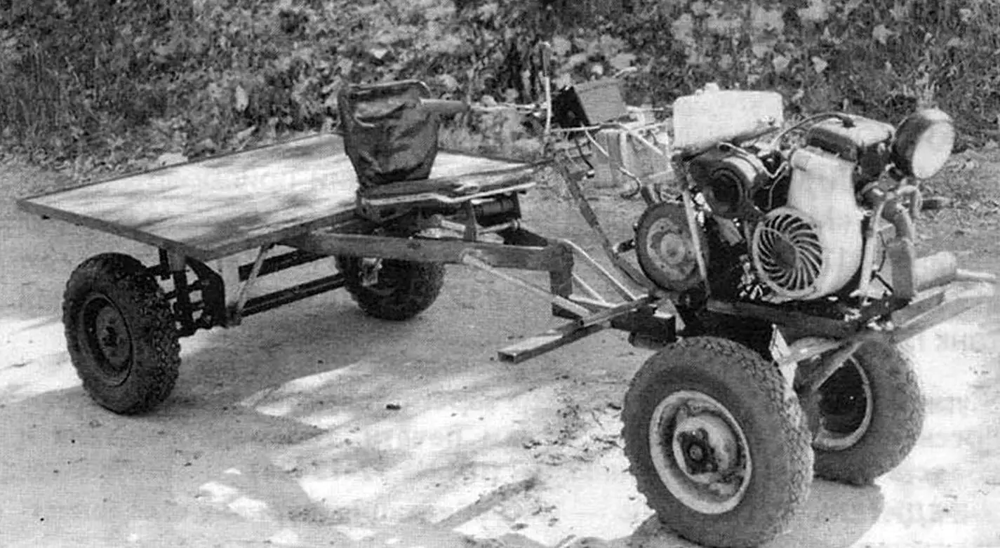
For cultivating the land in garden plots, I consider a walk-behind tractor to be the most suitable mechanism. It has small dimensions and consumes little fuel, has the necessary maneuverability and sufficient productivity. The ability to quickly replace some soil-cultivating tools on a walk-behind tractor with others (for example, a plow with a ripper, hiller or cultivator) makes this mechanism almost universal. If necessary, it can even be adapted for a vehicle for transporting goods over short distances along internal farm roads.
There are many models of walk-behind tractors on sale: from miniature “single-horsepower” to impressive ones – with a dozen or more horsepower, both imported and domestically produced. But even our units are not cheap, so I never made this purchase, but I was not left without a walk-behind tractor.
Having looked through the back issues of the Modelist-Constructor magazine again, I selected and studied several publications on the topic of self-manufacturing of walk-behind tractors. I was convinced that “not every god makes a pot”, and I believed in my own strengths, that I could make such a unit myself, fortunately I already had experience in self-made construction. I had some kind of metalworking tool, a welding machine, and most importantly – although not new, but a working engine from a cargo scooter. It predetermined the main dimensions and layout of the walk-behind tractor, transmission parameters, and a set of working bodies.
It took about a month to design the walk-behind tractor — develop the design taking into account the available power unit, auxiliary equipment and materials. At this stage, I also determined which parts needed to be ordered — I made the corresponding sketches for them.
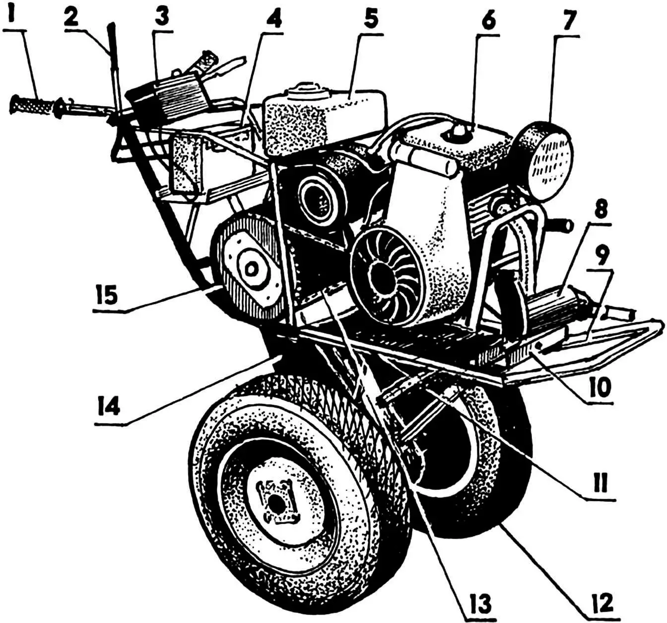
1 — steering wheel (from the Izh motorcycle); 2 — gear shift lever; 3 — instrument cluster; 4 — battery; 5 — fuel tank (3 l); 6 — engine (from the Muravei cargo scooter); 7 — headlight (car); 8 — muffler; 9 — frame; 10 — tensioner stop; 11 — skids; 12 — wheel (from the SMZ motorized carriage, 2 pcs.); 13 — first-stage chain; 14 — second-stage gearbox; 15 — first-stage driven sprocket
During the winter period, just in time for the spring “field” work, I managed to build a mechanical assistant and immediately test it in action. The machine basically met my expectations, although not 100 percent, but I will talk about this later.
The layout of the walk-behind tractor is such that all units are based on the frame. The frame is spatial, made according to a simple two-spar (duplex) scheme, only the front and rear parts of the side members are bent upwards. At the same time, their front ends are bent towards each other and welded together, and the steering wheel is welded to the rear ends (taken together with the control levers from the Izh motorcycle). The side members are made of steel water pipe with an outer diameter of 32 mm. In addition to the front joint, the side members are connected along the length by several more crossbars. Some crossbars “concurrently” perform other functions (for example, the front crossbar serves as a stop for the chain tensioner of the first stage of the transmission) or, conversely, parts of another purpose also serve as crossbars (as well as a platform for the battery).
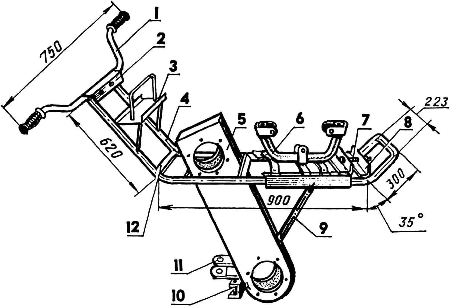
1 — steering wheel (from the Izh motorcycle); 2 — instrument panel mounting bracket (25×25 angle); 3 — platform and battery mounting bracket; 4 — frame side member (Ø32 pipe); 5 — second-stage chain transmission housing; 6 — sub-engine frame; 7 — first-stage power transmission chain tensioner (M10 bolt); 8 — chain tensioner stop; 9 — brace (Ø22 pipe); 10 — cultivator subframe attachment bracket (milled channel No. 8); 11 — transport trolley attachment bracket; 12 — crossbar (30×4 strip, 3 pcs.)
The frame parts also include the gearbox housing, which acts as a stand between the power unit and the chassis of the walk-behind tractor. The parts of the coupling devices for attaching a cultivator subframe or a two-axle trolley to the walk-behind tractor are welded to the housing at the bottom at the back. Together with the latter, the walk-behind tractor is transformed into a cargo vehicle.
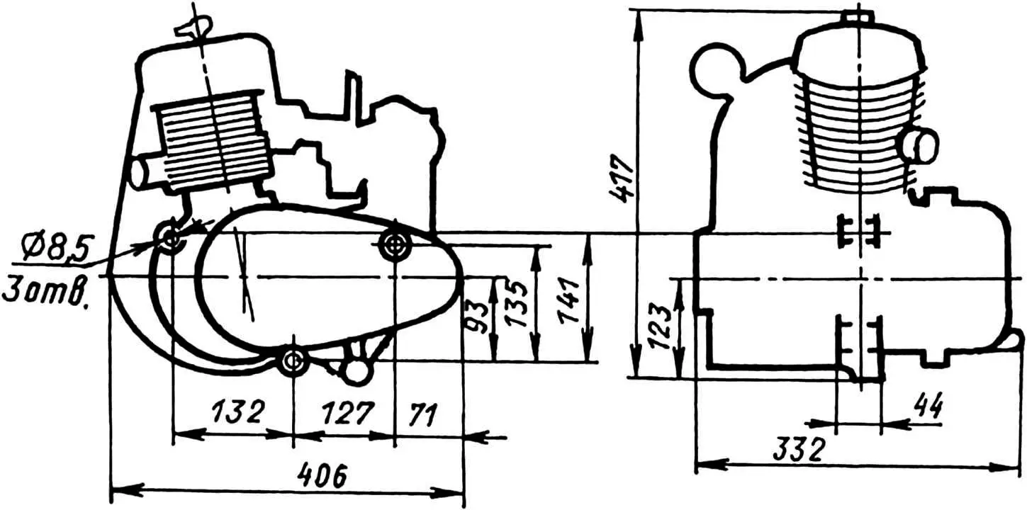
As was said at the beginning, the engine from the cargo scooter “Muravei” is used as a power unit. The engine is two-stroke, gasoline, 13 hp with forced air cooling, which is very desirable. Otherwise, this device would have to be manufactured anyway – even in the transport version, the speed of the walk-behind tractor is low, which means that overheating of the engine would be inevitable. The gearbox is four-speed, interlocked with the engine. The engine has a homemade muffler – a steel pipe with a diameter of 70 mm and a length of 250 mm with an exhaust hole of 16 mm, filled with metal shavings. The complex configuration of the exhaust tract is due to the layout of the walk-behind tractor and the need to remove exhaust gases to the side.
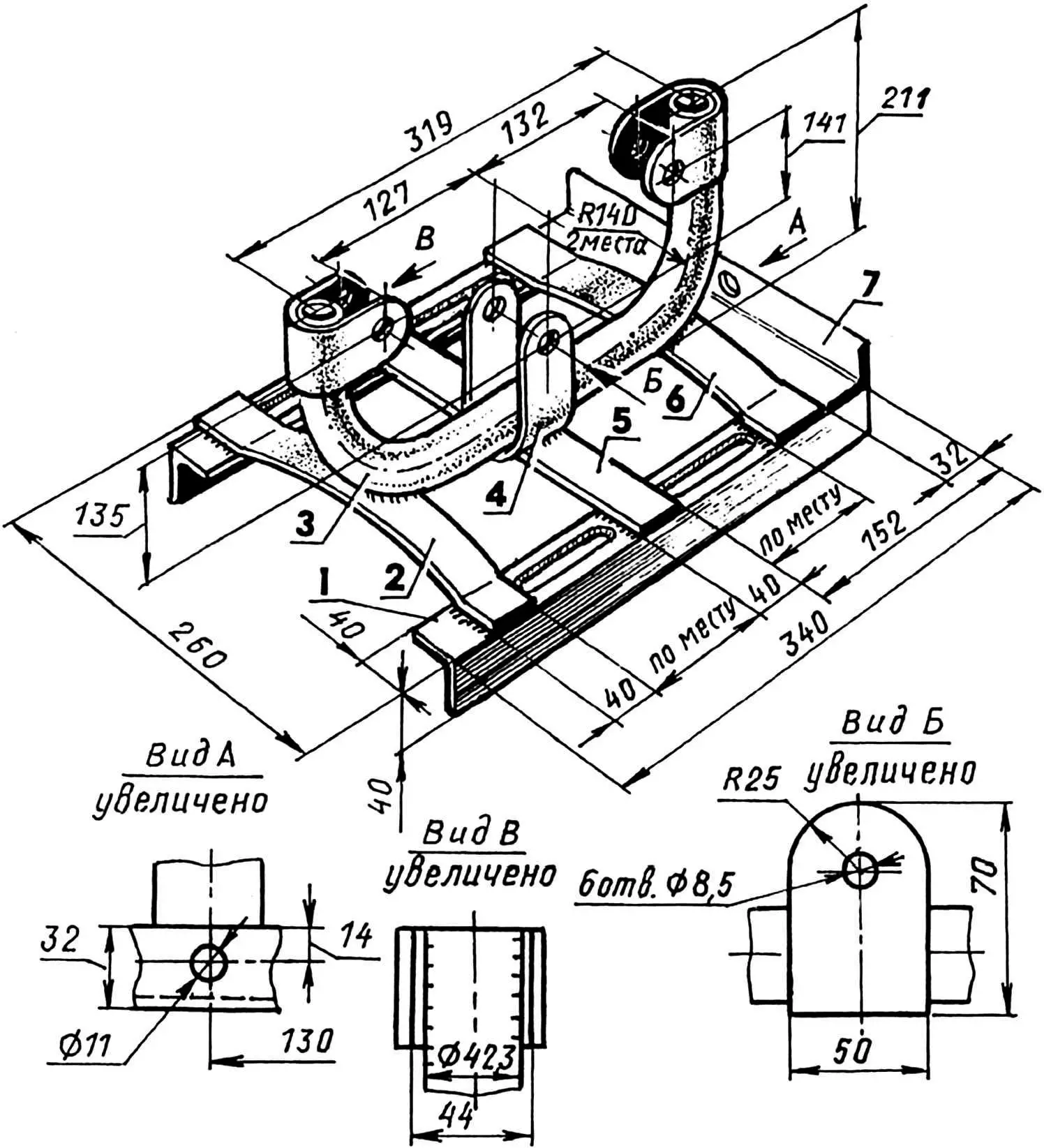
1 — runner (angle 40×40, 2 pcs.); 2 — rear crossmember; 3 — spine (steel pipe 1 1/4″); 4 — bracket-clamp (St3, strip 50×4, 3 pcs.); 5 — middle crossmember; 6 — front crossmember; 7 — crossmember (angle 32×32);
parts 2,5,6 are made of steel strip 40×4
The power unit is mounted on an underframe, which is a skid with an arc made of a water pipe with an outside diameter of 42 mm welded to its crossbars. Brackets are welded to the ends of the arc and in its middle part. Holes in the brackets for M8 fastening bolts were drilled on site in accordance with the holes in the lugs on the engine crankcase. Then the arc was installed with its backbone side and tack-welded to the middle crossbar on the skids. The outer crossbars were brought under the arc, bent, and their middle was also knocked out on site so that the line of their contact with the arc was the entire width of the crossbars. After that, the arc was welded to the crossbars along the contact lines, and the ends of the crossbars were welded to the skid guides. The guides are made of equal-flange steel angle 40 × 40. A crossbar is welded to the front ends of the guide runners from above. A hole for an M10 bolt is drilled in the middle of its vertical shelf. With the help of this bolt, also inserted into the front crossbar of the frame, the chain is tensioned (t = 12.7 mm) from the first stage of the gearbox during operation of the walk-behind tractor. The ability to move the runners along the side members is provided by four longitudinal grooves (two in each runner). Through these grooves, the sub-engine frame is secured to the main frame with four M10 bolts.
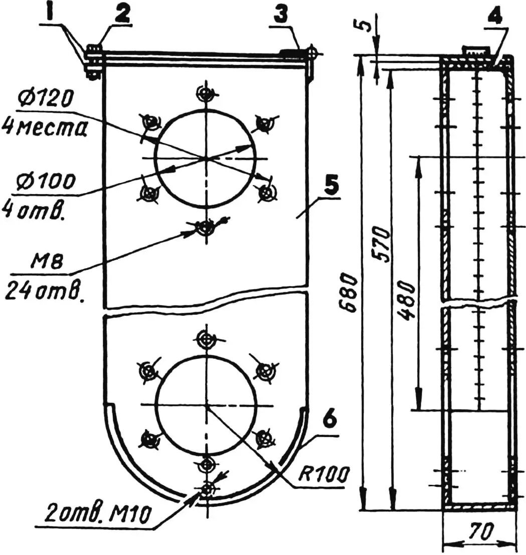
Chain reducer. To reduce the rotation speed and increase the torque when transmitting it from the output shaft of the power unit to the propeller (wheels or rippers), a two-stage chain reducer is used in the transmission system. The first stage consists of 17-tooth and 57-tooth sprockets. The pitch of their teeth, as well as the links of the chain connecting them, is 12.75 mm. The leading (17-tooth) sprocket is mounted on the output shaft of the power unit, the driven one is fixed on the outer flange of the primary shaft of the second stage. The second stage of the reducer, operating in more severe conditions, is reinforced, has a pitch of sprocket teeth and chain links of 19.05 mm. The leading sprocket has 11 teeth, the driven one has 25. Since this stage is in close proximity to the processed and therefore dusty soil, it is placed in a closed crankcase, which is mounted between two crossbars and frame side members and welded directly to the former, and to the latter – through steel spacers. For reliability, a brace is installed and welded between the crankcase and one of the crossbars.
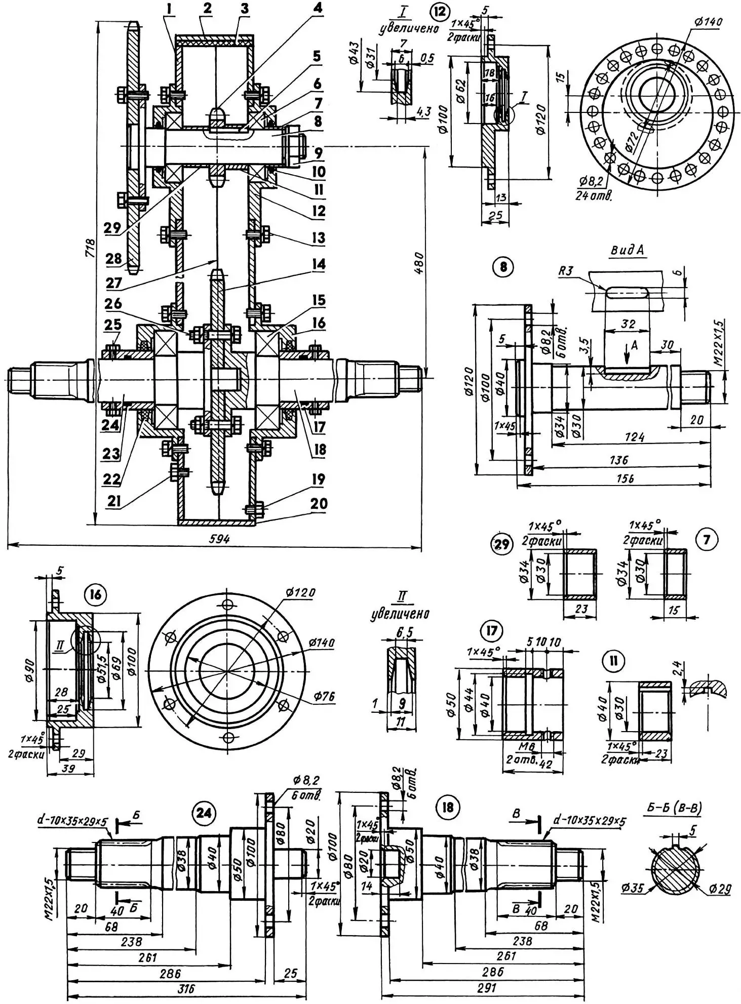
1 — housing (channel No. 20); 2 — cover (St3, sheet s5); 3 — gasket (oil-resistant rubber); 4 — second stage driving sprocket (z = 11, t = 19.05); 5 — key; 6 — bearing 206 (2 pcs.); 7 — compensation sleeve; 8 — shaft; 9 — nut M22x1.5 with spring washer; 10 — oil seal; 11 — spacer sleeve with keyway; 12 — eccentric bearing housing (St3, 2 pcs.); 13 — screw M8 with spring washer (30 pcs.); 14 — second stage driven sprocket (z = 25, t = 19.05); 15 — bearing 3008 (2 pcs.); 16 — bearing housing; 17 — sealing sleeve; 18 — left half-shaft; 19 — oil drain plug (M10 screw); 20 — housing bottom (St3, sheet s4); 21 — oil filler plug (M10 screw); 22, 23 — oil seals (2 pcs.); 24 — right half-shaft; 25 — M6 fixing screws (8 pcs.); 26 — M8 bolt; 27 — chain t = 19.05; 28 — first stage driven sprocket (z = 57, t = 12.7); 29 — spacer sleeve
1 — ears of the locking device; 2 — lock (M6 bolt); 3 – card loop; 4 – gasket; 5 — sidewall (2 pcs.); 6 – bottom
The crankcase is welded from two sections of channel #2, with the shelves milled along the length to a height of 35 mm. In the lower part, the channel walls are made in the form of a semicircle, and the shelves are cut off. Instead, a bottom is welded from a 4-mm steel sheet, bent in the form of a semi-cylinder along the semicircles of the walls. The crankcase is closed from above with a lid with a gasket made of oil-resistant rubber. In both walls, there are two coaxial holes with a diameter of 100 mm for the bearing housings, and around each of them there are six “orbital” (at the same distance from the edge of the circle and with equal intervals between them) threaded holes M8 for fastening the housings to the crankcase.
The lower bearing housings (semi-axles) are conventional, and the upper ones (shafts) are eccentric. By rotating them around the axis (in steps, at least by 15°), the tension of the chain of the second stage of the gearbox is adjusted.
The shaft of the second stage of the gearbox rotates in two ball bearings 206. The drive sprocket is connected to the shaft with a prismatic key and fixed inside the crankcase in the middle between its walls with two spacer bushings. The large driven sprocket is mounted on the centering boss of the right half-axle and secured between the opposite flanges of both half-axles with six M8 bolts. The lower teeth of the sprocket, together with several links of the chain, are immersed in an oil bath. When the walk-behind tractor moves, the chain transfers oil to the upper part of the crankcase, thus lubricating all the rubbing parts of the second stage. To prevent oil from leaking out, oil seals are installed in all bearing housings.
The rigid flange connection forms a single shaft from the half-axles, rotating in two 308 ball bearings. The ends of the half-axles have splined grooves – through them the torque is transmitted to the wheels or rippers.
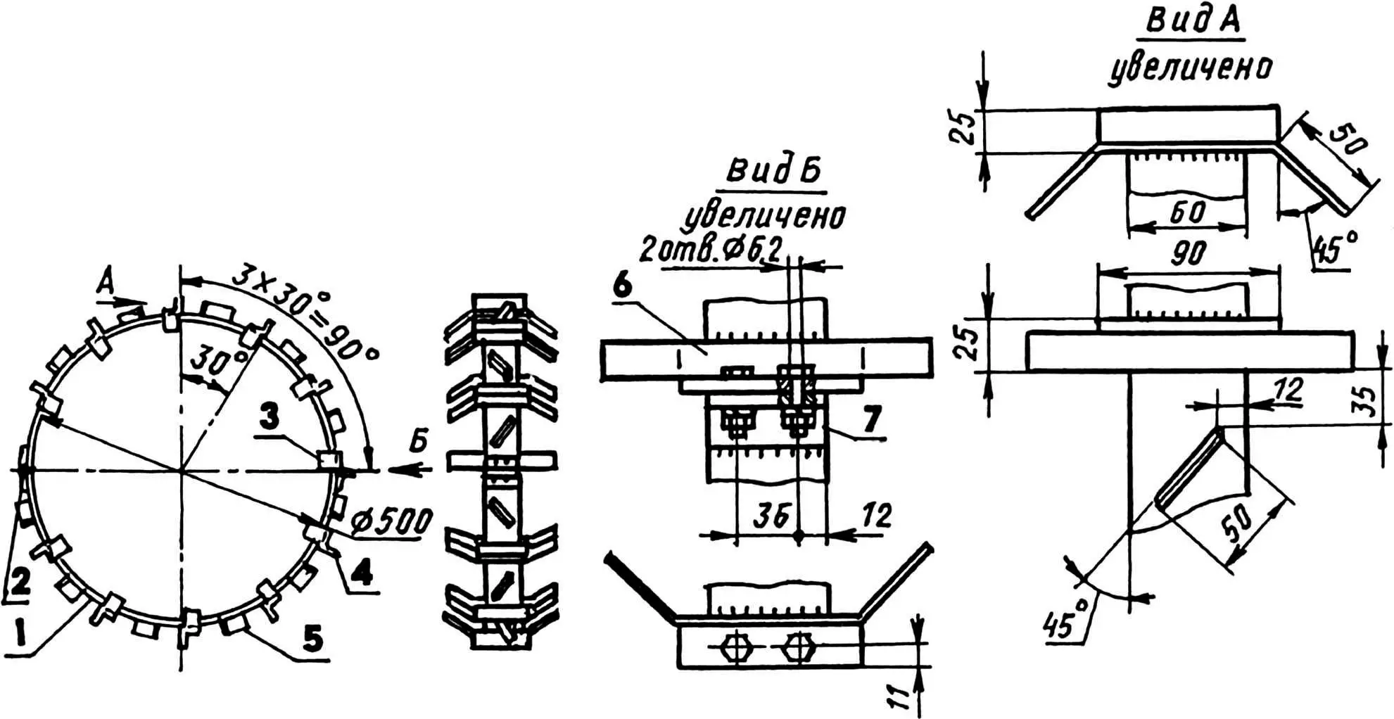
1 — half ring of the bandage (steel strip 60×5, 2 pcs.); 2 — hinge loop; 3 — locking lug; 4 — transverse lug (angle 25×25, 11 pcs.); 5 — diagonal lug (angle shelf, 12 pcs.); 6 — bolt M8 of the locking device (2 pcs.); 7 — mating half of the locking device (angle 25×25)
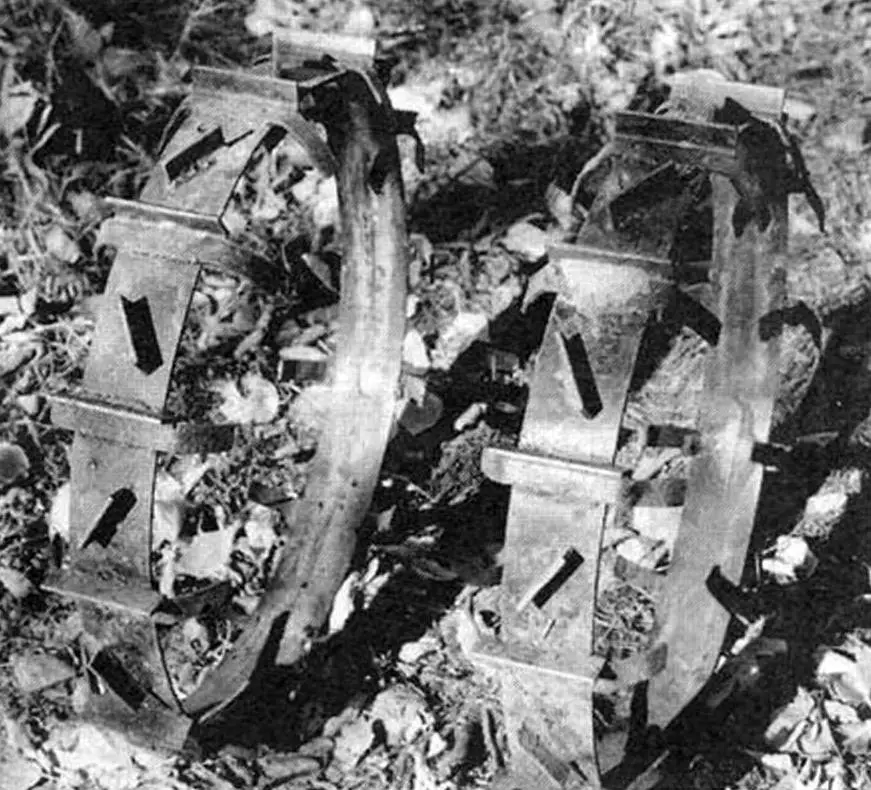
The wheels of the walk-behind tractor with tires measuring 5.00-10″ from the CM3 motorized carriage, homemade rippers. For better traction of the wheels with the ground during soil cultivation, as well as during winter operation of the walk-behind tractor, I put a homemade bandage with lugs on the tires of the wheels. I made the bandage from a steel strip with a cross-section of 90×5 mm, the lugs are made of a 25×25 mm corner. To prevent the bandage from slipping off the tire, I left antennae on the corner lugs, cutting off parts of the vertical shelves on their sides. I bent the antennae inside the bandage hoop, and welded the cut parts to it diagonally between the corners. For ease of installation on tires, the bandage hoop was made of two halves, connected on one side by a hinge, and on the other by a locking device, made like the one on the gearbox housing cover.
To install cultivators on a walk-behind tractor, I made a cultivator subframe from a 60×40 mm rectangular pipe. It is composite, has a T-shape, and the crossbar is detachable.
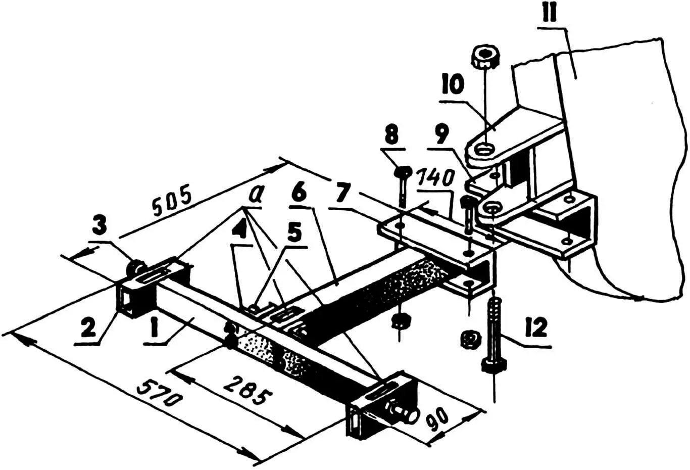
1 — crossmember; 2 — bracket (2 pcs.); 3 — M12 bolt (3 pcs.); 4 — crossmember mounting flange (30×30 angle, 2 pcs.); 5 — M8 bolt (4 pcs.); 6 — ridge; 7 — coupling device (channel No. 6.5); 8 — M8 subframe mounting bolt (2 pcs.); 9 — coupling device counterpart (milled channel No. 8: size between shelves 65 mm); 10 — clevis for connecting the bogie; 11 — gearbox housing; 12 — kingpin (Ø22 pipe with M22 thread and M22 nut);
parts 1,2,6 are made of rectangular steel pipe 60×40;
a – three rectangular holes for the cultivator paws (dimensions on site)
One, two or three cultivator paws can be installed on the subframe. These parts are factory-made, picked up from the “graveyard” of agricultural machinery. A coupling device made of channel No. 6.5 is welded to the front end of the subframe.
When connecting the subframe to the walk-behind tractor, the latter is inserted into the bracket (channel No. 8 with milled shelves – for a size of 66 mm between them) on the frame (gearbox housing), and both parts are connected with M8 bolts through the corresponding holes in both parts.
Initially, I planned to use the block to work with a single-share plow, which I also made myself. However, I had to give it up later – the work was slow and required a lot of physical effort.
Instead of a plow for soil cultivation, I made two rippers (cutters). They are installed for work in place of wheels.
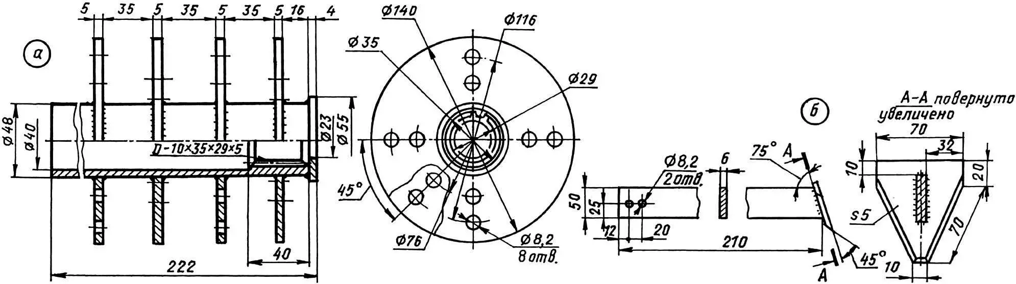
a – splined sleeve with four flanges and an end washer;
b – knife with cutter (16 pcs.)
The ripper is a set of knives with cutters, fixed with M8 bolts on flanges, mounted and welded to the bushing. The inner diameter of the bushing is slightly larger than the diameter of the splined part of the axle shaft. The knives are made of a 50×60 mm steel strip, the cutters are taken from the cutting parts of a decommissioned mower.
The cross member of the cultivator subframe is disconnected
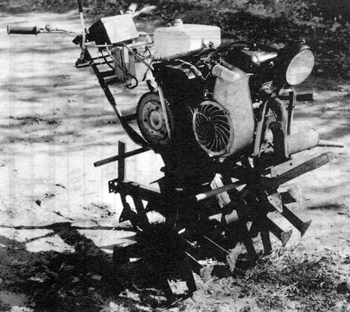
To process the soil with rippers, one or two paws must be installed in the cultivator subframe to create a braking moment. Then the rippers, rotating, slip, dig into the soil and break it into small fractions. The braking moment is adjusted by installing a different number of paws and the degree of their deepening. With a well-adjusted moment, the walk-behind tractor moves evenly forward itself and the plowman-operator easily controls it. If the processed area has ascents and descents, then the braking moment will have to be adjusted manually, by the level of immersion of the blades into the ground due to the efforts on the steering wheel.
The depth of soil cultivation by rippers is about 200 mm – this is exactly the height of the shovel bayonet. The soil after loosening becomes soft, with a smooth surface, and does not require harrowing.
As mentioned at the beginning, the walk-behind tractor can be converted into a tractor for transporting goods. For this purpose, I made a two-wheeled semi-trailer for it. The front axle of the motorized carriage (with wheels) was used as its chassis. The main frame is made of a rectangular steel pipe 60×30 mm in a two-spar design with two crossbars. The spars converge at the front, and the seat is mounted in this place.
1 — main frame (steel, pipe 60×30); 2 — platform edging frame (steel, angle 25×25); 3 — additional ties and braces (pipe 1/2″, angle 35×35); 4 — seat; 5 — drawbar (steel rectangular pipe 60×30); 6 — swivel coupling device; 7 — stand (steel rectangular pipe 60×30, 2 pcs.)
The drawbar of the trolley is made stepped to bring the coupling device as close as possible to the wheel axis. This makes it easier to control – like machines with an articulated frame. The drawbar steps are reinforced with braces made of a half-inch pipe. Footrests are welded to the drawbar from below. The coupling device is simple, made as a swivel, so that the walk-behind tractor can turn relative to the horizontal longitudinal (conditional) axis on an uneven road or slopes. A frame-edging of the cargo platform is mounted on top of the main frame, made of 35×35 mm steel angle. Additionally, the structures are reinforced and connected to each other with several more connections.
The bogie frame is connected to the bridge levers by means of pillars made of the same pipe as the frame. The pillars are reinforced with struts.
The frame of the platform is covered with downs with a thickness of 25 mm thick. Later, I think to make both shooting or leaning sides to the platform.
The electrical equipment of the walk-behind engineer is 12-volt. The battery consists of two 9MT-14 batteries. 90 watts electric generator. The ignition coil and the electric steel is standard. Farah – car.
A. Narvatov
Recommend to read
 HOW TO EXTEND THE LIFE OF THE BULB?
If you are tired to constantly change the bulb, use one of the tips below. But in all cases success is achieved through a substantial reduction in voltage. In the daytime and especially... ELECTRODISCO?
No, just securing the bottom of the Ironing Board extension socket, you can remove the wire from under the feet to ensure additional comfort and to comply with the rules technici security.
