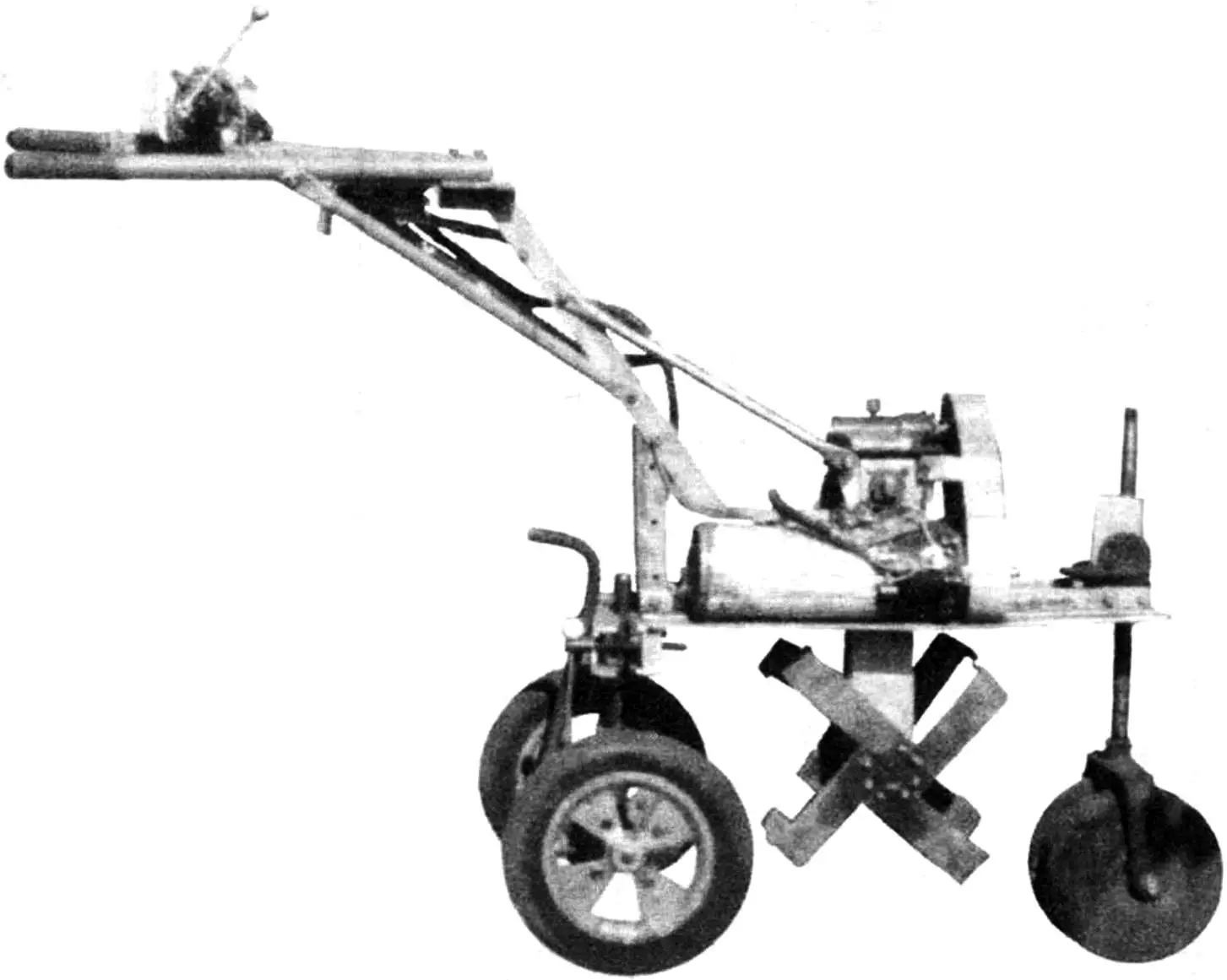
Garden plot owners are very fond of “Krot” (Mole) cultivators with gasoline engines. At first, I was also extremely happy with such a mechanical assistant. However, over time, I still decided to get rid of the noise and harmful exhaust of the gasoline engine and make an environmentally friendly electric cultivator, safe from electric shock.
For the cultivator, an electric motor with series excitation is needed, in which the torque increases with increasing load. The ST-8 starter from the GAZ-51 truck is best suited for this purpose. The idea to use the ST-8 was “suggested” to me by a publication titled “Electric Karting — to Be!” in the “Modelist-Konstruktor” magazine No. 1 for 1981.
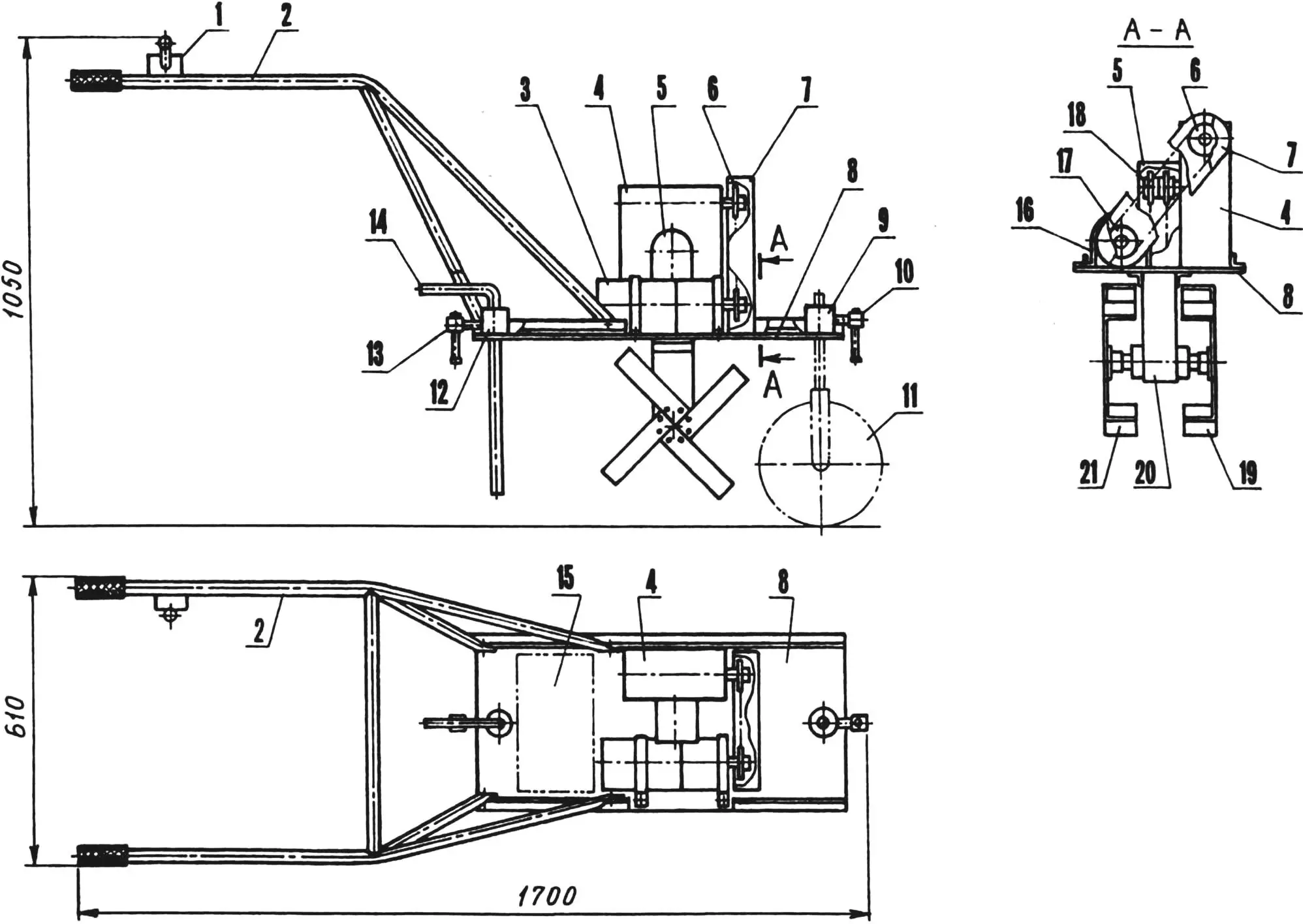
1 — rotary switch; 2 — control handles; 3 — motor; 4 — reduction worm gear (i = 60); 5 — housing of secondary chain drive branch; 6 — driven sprocket on input shaft of gearbox; 7 — housing of primary chain drive branch; 8 — power platform; 9 — mounting bushing of front chassis strut; 10,13 — locking screws M10; 11 — front chassis strut (in transport configuration); 12 — mounting bushing of brake pin in working configuration and rear chassis strut — in transport; 14 — brake pin; 15 — place for ballast weight of 20 kg; 16 — motor mounting clamp (2 pcs.); 17 — drive sprocket on motor shaft; 18 — sprocket block on output shaft of gearbox; 19 — left cultivator cutter; 20 — running gear housing; 21 — right cultivator cutter
Having obtained such a starter, I still modernized it a bit.
First, I shortened its shaft slightly.
Second, I machined a new front cover from duralumin alloy D16TV and pressed a ball bearing 204 into it. In the rear cover (on the brush side), I left the standard bronze bearing, but significantly improved its lubrication by installing a cap oiler with lithol.
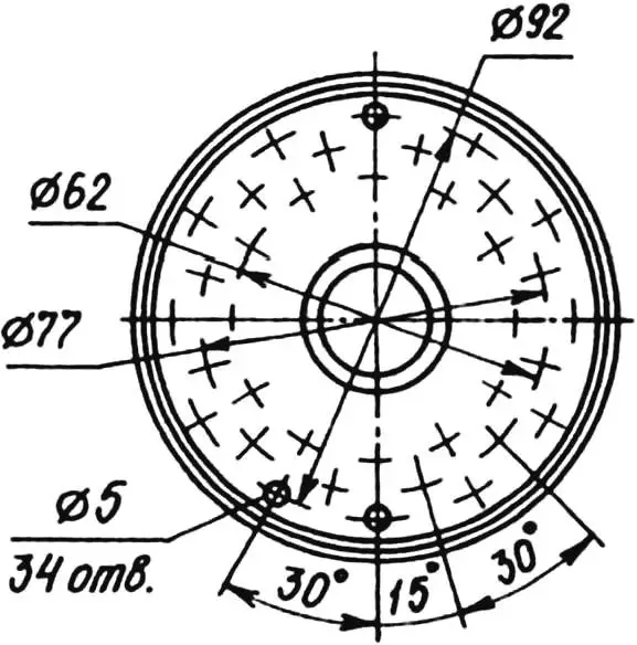
Third, I drilled many through ventilation holes with a diameter of 5 mm in both starter covers.
Air is forced through these holes by a fan, the impeller of which I mounted on the shaft of an electric motor model ME-7B from a ZIL-164 truck. I placed the fan in a housing made of sheet duralumin (alloy D16AMO) 2 mm thick, and positioned the housing coaxially behind the starter and secured them with a clamp made of duralumin strip.
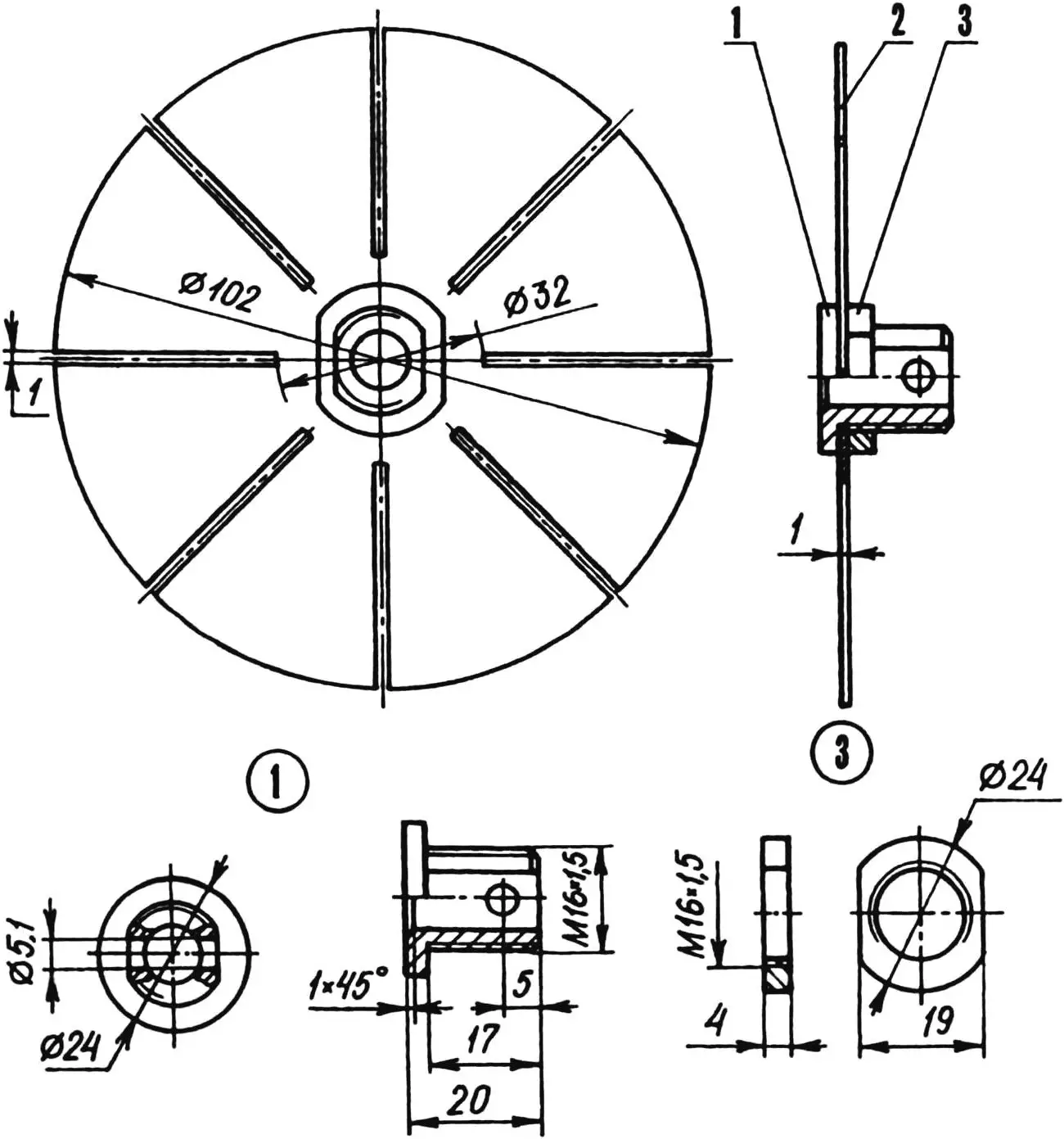
1 — hub (St3); 2 — blade block (D16AMO, sheet s1); 3 — nut M16x1.5
On the tail of the shortened starter shaft, I mounted a drive sprocket (z = 15, t = 12.7 mm; from K-125 motorcycle), coupled (welded) with a homemade bushing-hub. I connected this sprocket with a roller chain to a driven sprocket (with exactly the same parameters: z = 15, t = 12.7 mm) on the input shaft of the reduction worm gear. The mentioned gearbox with a gear ratio i = 60 was installed on some aircraft and came to me decommissioned after its service life was exhausted.
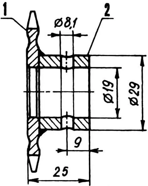
1 — drive sprocket (z = 15, t = 12.7; from K-125 motorcycle); 2 — hub (St3)
For convenience of narration, I would call this chain drive branch between the starter and the gearbox primary. To make it work smoothly, I thoroughly coated the chain with graphite grease.
Next, using the method gleaned from the article “Sprocket for Chain Drive” in No. 11 for 1975 of the “Modelist-Konstruktor” magazine, I made four more sprockets from suitable steel 12ХН3А, but with 11 teeth and a pitch of 15.875 mm. Their working surfaces had to be hard and wear-resistant, so I used carburizing and heat treatment.
Having fixed two such sprockets on the end of the output shaft of the worm gearbox and two more on the working shaft, I connected them with two roller chains. This chain drive branch can be called secondary. For its tension, I used thin metal shims under the gearbox, and for protection from contamination — a solid cladding of the running gear housing.
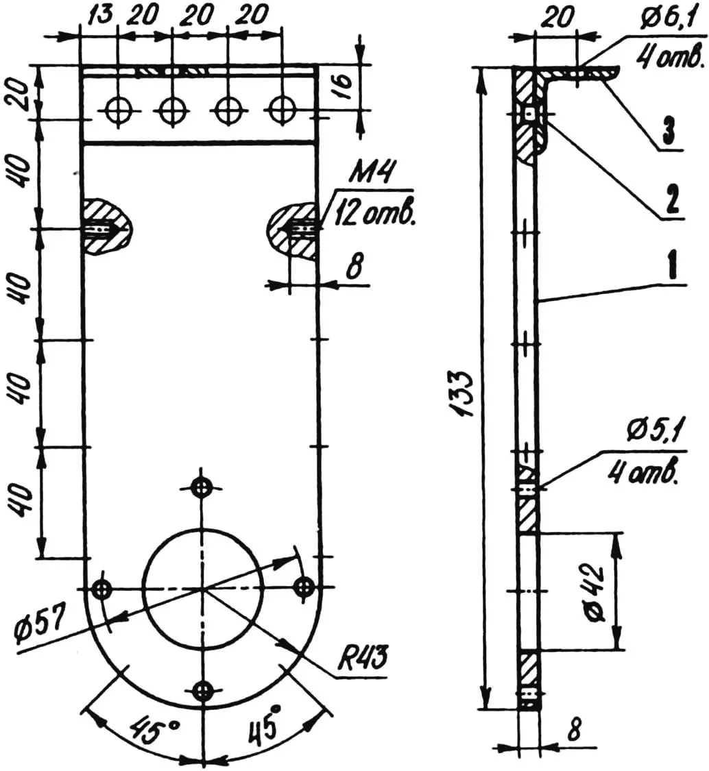
1 — cheek (D16TV, sheet s8); 2 — rivet (D16, Ø6, 4 pcs.); 3 — bracket (D16TV, angle 30x30x4)
The chains are lubricated during operation in a so-called oil bath — in a certain volume of transmission oil poured into the running gear housing. At the very bottom of the housing, the working shaft carrying the cultivator cutters rotates in two bearings 206, hidden in housings with felt seals.
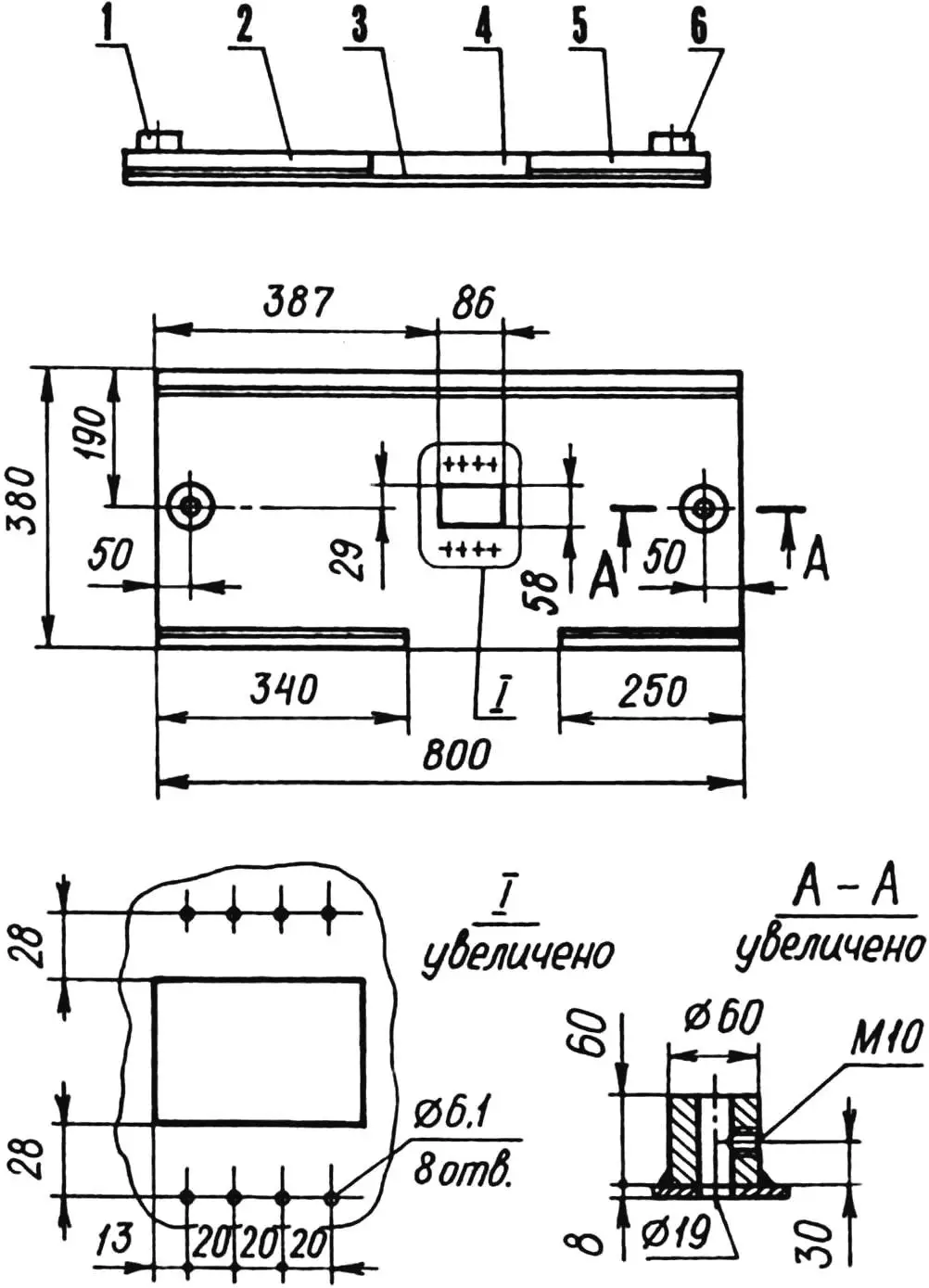
1,6 — chassis strut mounting bushings (steel 45); 2,4,5 — stiffening ribs (angle 30x30x4); 3 — platform (steel 45, sheet s8)
I installed all these units on a power platform made of sheet steel and reinforced with welded longitudinal stiffening ribs made of steel angle. I attached the control handles of the electric cultivator to the ribs with M6 bolts. I welded the latter from sections of steel pipe. I put rubber handles on the two rear ends of the pipes, which the operator holds; I flattened the four front ends and drilled holes in them for mounting bolts.
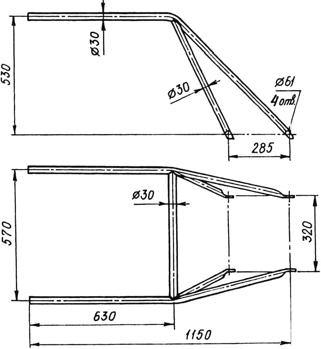
For manually moving the unit over short distances, I made a removable chassis for it, consisting of two struts. The front strut has one dual-tire wheel (homemade, with tires from a children’s bicycle), the rear — two wheels (from a larger children’s bicycle). The struts are fastened in special bushings welded to the platform at the front and rear, with locking (clamp) screws.
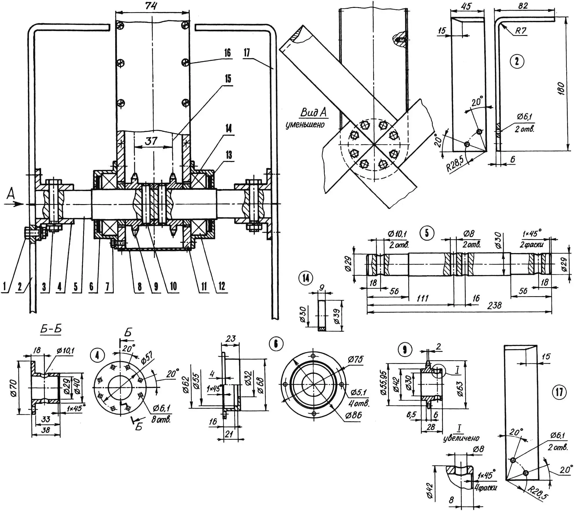
1 — bolt M6x20 (16 pcs.); 2 — left cultivator cutter blade (St3, strip 45×6, 4 pcs); 3 — bolt M6x53 (2 pcs); 4 — hub (30ХГСЛ, 2 pcs); 5 — working shaft (30ХГСА); 6 — bearing housing (D16TV, 2 pcs); 7 — screw M5x10 (8 pcs); 8 — housing cladding (D16AMO, sheet s2); 9 — running sprocket (12ХНЗА, total 4 pcs); 10 — pin Ø8 (2 pcs); 11 — housing cheek (D16TV, sheet s8, 2 pcs); 12 — bearing 206 (2 pcs); 13 — seal (felt, s3, 2 pcs); 14 — spacer bushing (D16TV, 2 pcs); 15 — roller chain (t = 15.875 mm, 2 pcs); 16 — screw M4x8 (24 pcs); 17 — right cultivator cutter blade (St3, strip 45×6, 4 pcs.)
At the edge of the field, before starting soil cultivation, I remove both struts from the electric cultivator. Instead of the rear one, I insert a so-called brake pin and lock it with a clamp screw. By adjusting the depth of this pin into the ground, I control the speed and depth of cultivation.
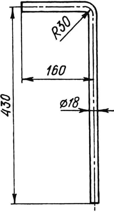
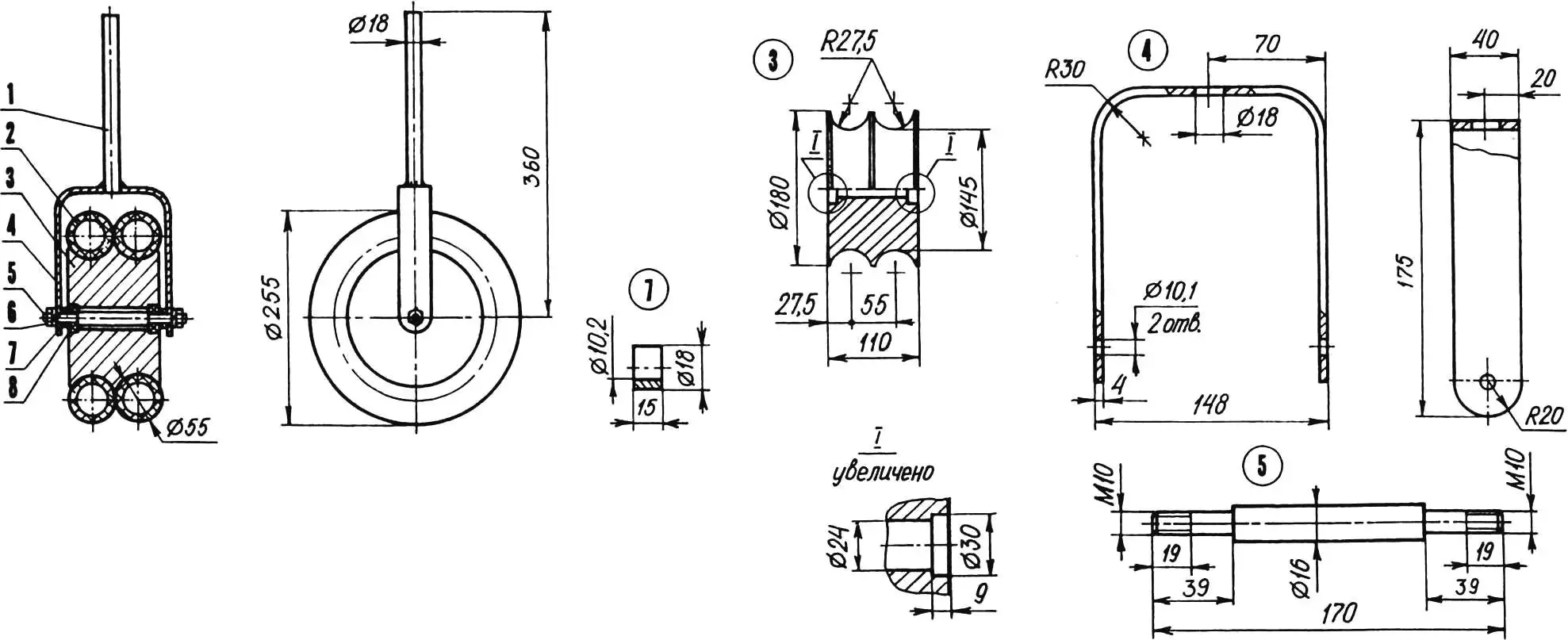
1 — mounting pin (St3, rod Ø18); 2 — tire (from children’s bicycle wheel, 2 pcs.); 3 — wheel hub (D16TV); 4 — fork (St3, strip 40×4); 5 — axle (St3, rod Ø16); 6 — nut M10 (2 pcs.); 7 — spacer bushing (St3, 2 pcs.); 8 — bearing 160200 (2 pcs.)
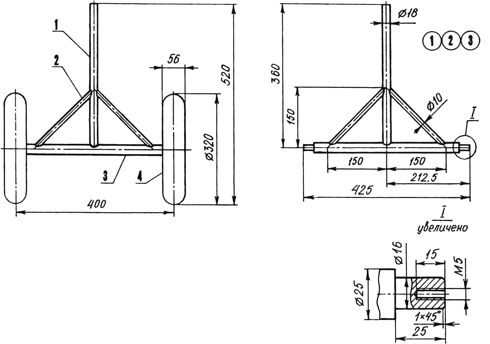
1 — mounting pin (St3, rod Ø18); 2— brace (St3, rod Ø10, 2 pcs.); 3 — axle (St3, rod Ø25); 4 — wheel (from children’s bicycle, 2 pcs.)
Because the unit turned out to be light, the cultivation depth was initially insufficient. I had to weight it with a removable ballast weighing 20 kg, which I placed at the center of gravity of the machine. This made it possible to maintain a processing depth of 160—190 mm with a soil strip width of 250 mm captured by the cutters. The productivity when working with my electric cultivator is the same as with the “Krot”.
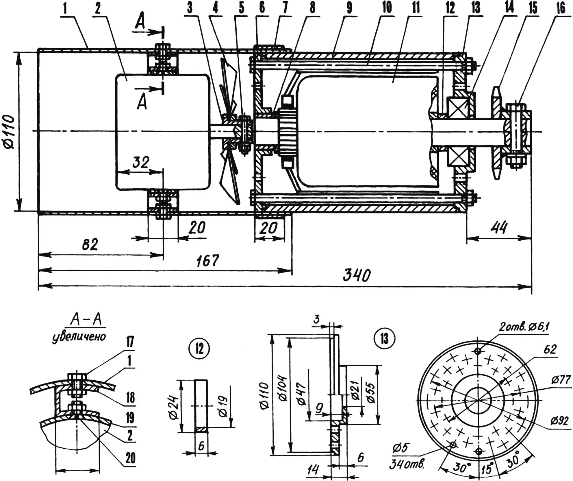
1 — fan housing (D16AMO, sheet s2); 2 — fan electric motor (model ME-7B, from ZIL-164 car); 3 — fan impeller hub with nut; 4 — fan impeller blade block; 5 — bolt M5x20; 6 — rear starter housing cover (standard, modified); 7 — clamp (D16AMO, strip 20×2); 8 — standard bushing-bearing (bronze); 9 — starter housing; 10 — tie bolt M6 (2 pcs.); 11 — starter rotor; 12 — spacer bushing (brass LS59-1); 13 — front starter housing cover (D16TV); 14 — bearing 204; 15 — sprocket-hub block; 16 — bolt M8x35; 17,20 — bolts M5 (8 pcs.); 18 — spacer (D16AMO, strip 20×2, 4 pcs.); 19 — band (D16AMO, strip 20×2)
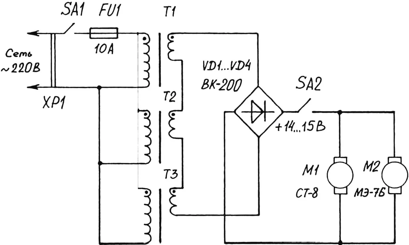
As a power supply unit for the ST-8 starter and ME-7B fan motor, a welding transformer could be used, but it is quite expensive. Therefore, I took a different path. I took three low-power (about 500 W each) transformers, removed their secondary windings and wound busbars on the freed places, the cross-sectional area of which is 25 mm2; then I connected the primary (mains — 220 V) windings in parallel, and all secondary (4—5 V each) — in series-aiding. As a result, at the output of the transformers, alternating current with a voltage of 14—15 V was obtained, which is immediately rectified by a bridge of VK-200 diodes (replacement of diodes of this brand is possible with any other with a working current of 200 A, which is very convenient).
The power supply unit turned out to be quite heavy, and I had to mount it on a separate four-wheeled cart. It connects to a 220 V mains socket with a forty-meter cable, the core cross-section of which is 2.5 mm2, and to the cultivator — with a double (25×2 mm2) electric welding cable 12 m long.
To supply constant voltage of 14—15 V to the starter, I used a standard rotary switch (25 A, 250 V) with an extended handle, in which I “paralleled” three power lines. I placed the switch on the left control handle of the cultivator.
Thus, thanks to the use of isolating step-down transformers for 220/14 V, it was possible to ensure complete safety from electric shock when working with the cultivator even on waterlogged soil (of course, with strict observance of other safety requirements).
The electric cultivator fully justified my hopes. For four seasons now, I have been effortlessly processing my entire garden plot with it.
V. LEBEDEV
Recommend to read
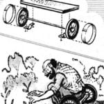 TABLE GARDENER
Most of the work in the garden tedious due to the fact that one has to bend down. Create some "comfort" will help mobile stool, consisting of small plates and axle with wheels (you can... IN HARNESS – INTROTSIKL
In October 1996 in the Udmurt Republic celebrated the 65th anniversary of the system of children's technical creativity. In 1931 in Izhevsk was opened the first children's technical...
