Indeed: how to remove combustion products from a stove without a good chimney? Without it, there will be no necessary draft either.
There are three main types of chimneys — wall-mounted (inside capital brick or stone walls, also called wall chimneys); root (brick risers standing separately from the stove); mounted (directly on the stove top).
WALL CHIMNEYS
Installing smoke risers in stone or brick walls is convenient because they do not require additional material consumption. These are the most economical pipes, laid during the wall construction process itself.
Most often, the smoke riser is located in internal walls. It can be made in external masonry only in exceptional cases and only by taking measures to prevent the smoke gases from cooling: this leads to condensation on the inner surface of the pipe and reduced draft. To prevent this, pilasters are provided at the location of the pipes, the walls of which must be at least half a brick thick. The total thickness of the external wall “to the smoke” (pipe channel) is then calculated for the prevailing low temperature. At frosts of 30°C and above, the thickness of the external wall should be 2.5 bricks (650 mm); at temperatures from minus 20°C — a wall of 2 bricks (510 mm), for milder winters, masonry of 1.5 bricks (380 mm) is sufficient. To prevent condensation, the external side of the wall with the smoke riser must be insulated with plaster on slag sand, with a layer thickness of 25—30 mm.
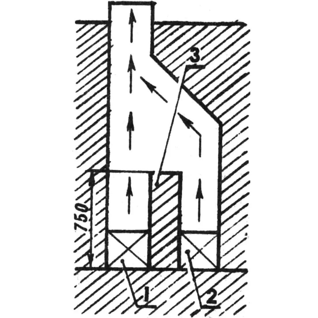
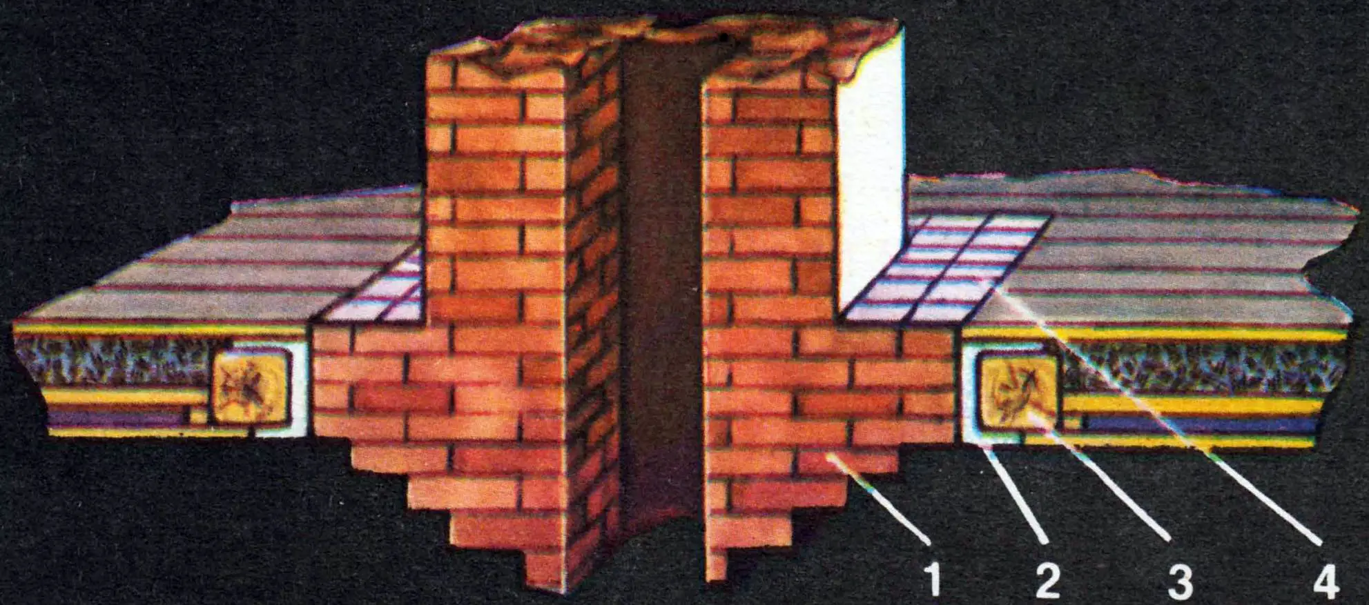
1,2 — connection points of stoves to the chimney, 3 — brick partition wall.
Even if walls are built from natural stone, slag blocks, or monolithic concrete, smoke channels are laid from red solid (without gaps) brick. Ventilation channels should be located next to them. Sometimes channels are made from asbestos-cement pipes of the required diameter. Silicate brick is prohibited.
The smoother and more even the inner surface of the channels, the easier the smoke will pass through them, and therefore the better the draft.
Each stove should have its own separate smoke channel; but a ventilation channel can be one for two smoke channels. If stoves on different floors are connected to one smoke channel, draft interruptions are possible. In exceptional cases, however, one chimney is used for two stoves, but in this case a partition is made, that is, a brick wall at least 750 mm high, and the channel (chimney) itself must be at least 1X1/2 brick in size.

1 — steel angles, 2 — brick masonry, 3 — casing (metal sheet), 4 — cleaning door.
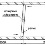
When the stove does not adjoin the wall directly but is at some distance from it, a so-called smoke pipe or cross-over sleeve, made of brick and having a smoke damper, is used to connect it to the wall chimney. This horizontal channel no more than 2 m long is laid on two steel angles resting on the stove masonry and the wall. The thickness of the horizontal walls of the sleeve is at least half a brick; if the sleeve is enclosed in a casing of sheet steel (most often roofing, painted), then the lower part can be 1/4 brick, and the upper part is still half a brick (in two rows of quarter-brick masonry) — this is important from a fire safety perspective. Cleaning the sleeve from soot is done through a special door that must close tightly. Usually, cast iron hermetically closing doors are used.

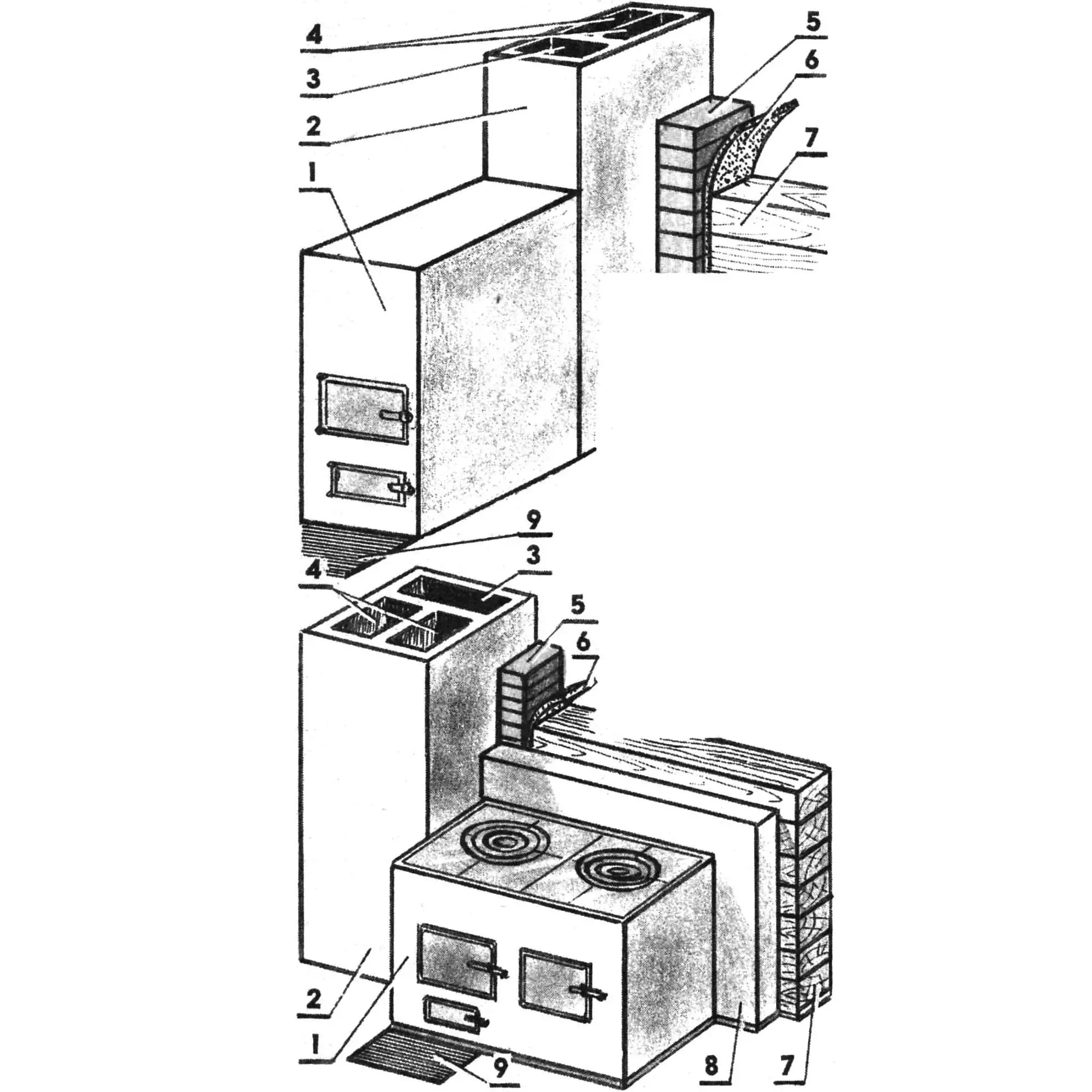
1,2 — stoves, 3 — smoke channel of the upper level stove, 4 — ventilation channel of the upper level, 5 — pipe, 6 — smoke channel of the lower level stove, 7 — ventilation channel of the lower level, 8 — ventilation grille.
In two-story houses (for example, with an attic), stoves are most often placed one above the other. In this case, only the upper floor chimney is straight, and the lower stove is connected to it by a so-called offset. It is made at an angle of 60°. The peculiarity of offsets is that their lower parts are closed with a whole brick laid flat. Moreover, the place where the weight hits when cleaning the chimney is laid with a more durable material — for example, natural hewn stone. In monolithic walls, offsets can be round channels into which asbestos-cement or ceramic pipes of the required cross-section are laid.
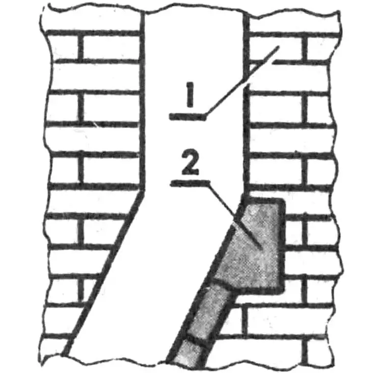
1 — brick masonry, 2 — strengthening layer (hewn stone).
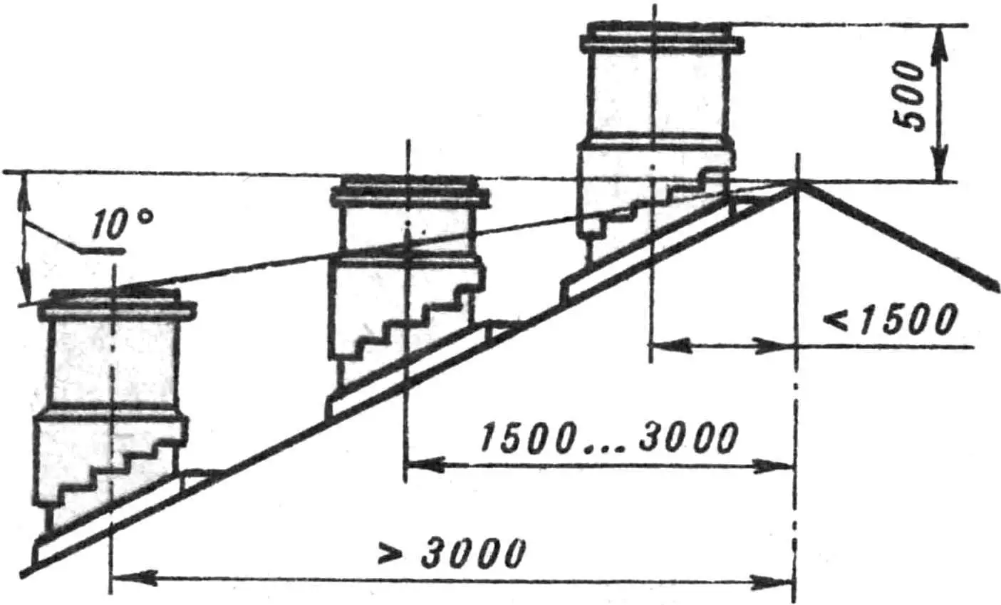
Internal brick walls, in which smoke risers are usually located, end at the level of the upper floor. Above, the chimneys become the actual smoke pipes, which are led through the roof of the building above or below the ridge — this depends on the distance to the ridge, measured along a horizontal line. If the pipe is no more than 1500 mm from the ridge, its height should be 500 mm above the ridge itself. At a distance of 1500—3000 mm, the top of the pipe should be at the same level as the ridge, and beyond 3000 mm,— below the ridge, on a line drawn at an angle of 10° from the horizontal. But in all cases, the smoke pipe is raised above the roof surface by at least 500 mm to avoid it being buried in snow.
The height of the pipe and the draft in the stove are interrelated; therefore, you should first “try on” a pipe made of roofing steel, raising it until a good result is obtained. After that, the permanent pipe is laid.
It should be borne in mind that wooden sheathing or rafters must be at least 150 mm away from the pipe. And to prevent water from the roof from entering the attic space along the pipe, a widening called a flaring is made during masonry, and a collar of roofing steel is placed under it.
In the attic, the pipe is whitewashed with lime whitewash: dark cracks that appear on it are easily noticeable and must be repaired immediately.
ROOT PIPES
They are installed when there are no wall channels, for example, in wooden buildings that do not have brick internal walls. Such pipes are laid on a good foundation, which should not adjoin the building foundation. Masonry is carried out with careful bonding of joints.
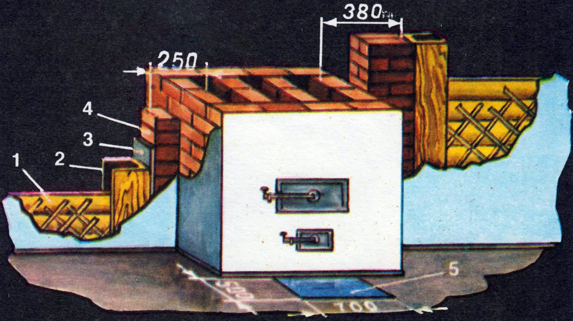
1 — stove (cooktop), 2 — root pipe, 3 — ventilation channel, 4 — smoke channels, 5 — brick separation, 6 — thermal insulation (felt), 7 — wall (wood), 8 — brick wall, 9 — metal sheet.
The wall thickness of pipes for heating stoves and kitchen hearths (cooktops) should be half a brick. If it is necessary to connect two or more stoves to them, cross-over sleeves are used, which are located inside the room (unlike the so-called horizontal ducts previously used in attics, not recommended both from a fire safety point of view and to prevent condensation, which is inevitable when placing a channel in the attic).
MOUNTED PIPES
They are built directly on the stove and are, as it were, its continuation. It is much better to install a mounted pipe not directly on the stove neck, but to first lay a reinforced concrete slab with a hole (or holes) on it. This option is convenient because it allows repairing the stove without disassembling the pipe itself. In this case, the stove walls are disassembled and repaired in turn: the slab rests on the other three walls of the stove neck.
MASONRY OF SMOKE PIPES ON THREE CHANNELS
When laying, attention must be paid to good joint bonding: they must overlap by half a brick.
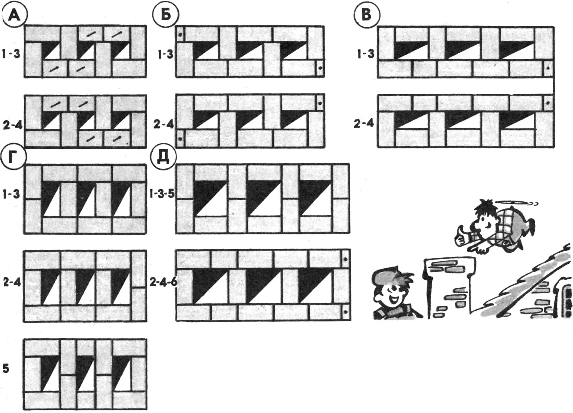
1,3, 5 — odd rows, 2, 4, 6 — even rows (quarter brick marked with a dot, three quarters with a dash).
Depending on conditions, pipes have to be laid on two and three chimneys or channels. Joint bonding in this case plays a huge role. For clarity, the masonry of even and odd rows is shown using bricks of different sizes: three quarters, halves, and quarters. (In one of the variants with channels with a cross-section of 1/2X1 brick, the fifth row is shown solely to bind the masonry more firmly through four rows.)
MASONRY OF PIPE WITH FLARING AND FLARING
Before starting to lay the pipe, you should know what parts it consists of. It is known that a mounted pipe is always installed on the stove neck, which is not brought to the interfloor or attic floor by two or three rows of masonry.
A smoke damper or flue damper (or both together — for tighter closing) is installed in the stove neck. Above the stove neck, when approaching the interfloor or attic floor, the pipe masonry is gradually widened, forming a separation or flaring with a thickness (counting “from the smoke”) of 260 or 380 mm. This is done for fire safety: the thicker the flaring, the better. It is laid in several rows in height. Above it, through the attic space, goes the riser, that is, the straight part of the pipe, which is brought to the roof itself. Above the roof, a second flaring, called a flaring, is made, which overhangs 60—100 mm over the roof on all four sides: this ensures the drainage of water flowing down the pipe onto the roof. Above the flaring, the pipe neck of the same cross-section as the riser is laid. Further, the masonry is widened again, forming a cap. To protect the pipe from destruction, a cap or weather vane made of roofing steel is installed above it, which, in addition to protective functions, also improves draft in stoves.

1 — pipe riser, 2 — reinforced concrete slab, 3 — flaring masonry, 4 — pipe neck.
All protruding parts of the pipe above the roof should be covered with roofing iron or treated (coated, plastered) with cement mortar, giving it a slope on the protruding parts that ensures water drainage. The pipe itself must be plastered: this way it will last longer.
As mentioned above, the cross-sections of chimney channels are different, which means that the flaring and flaring must be laid differently, but strictly bonding the joints. Let’s consider the masonry of the flaring and flaring with a smoke channel cross-section of 130X260 mm, that is, one brick.
MASONRY TECHNIQUE
Depending on the thickness of the joints, the channel dimensions can be 10 mm larger. The masonry of the flaring and flaring is also performed with the calculation that they increase in length and width by 1/4 brick (60—70 mm) per row due to the joints.
The masonry of the flaring begins on the stove neck 1—2 rows below the floor. In this example, the flaring consists of six rows.
The first row is the pipe neck, made of five bricks with the dimensions of the smoke channel indicated above, and with external sides of 510—380 mm.
The second row is the actual beginning of the flaring, with external dimensions of 590X450 mm. To obtain such widening and lengthening compared to the first row, quarters and halves of bricks are inserted into the masonry. Inside the flaring, to maintain the channel dimensions, “plates” — split brick 30—40 mm thick — are inserted.
The third row of the flaring has dimensions of 650X510 mm, and inside, “plates” of brick about 60 mm thick are inserted. The dimensions of the fourth row will be 710X570 mm, and the thickness of the inserted “plates” is 90—100 mm.
The fifth row will already be entirely of whole brick; the same goes for the sixth, only strict joint bonding is observed. When increasing the height of the masonry, the fifth and sixth rows are repeated.
The seventh row is already the beginning of the masonry of the pipe riser in the attic, made of five bricks. The riser is brought out one or two rows above the roof level.

1 — pipe riser, 2 — wooden formwork for mortar, 3 — clay layer, 4 — reinforcement bars.
A — flaring from reinforced concrete box: 1 — pipe riser, 2 — box; 3 — backfill (slag, expanded clay).
Then they proceed to laying the flaring, with careful joint bonding, in nine rows, each of which protrudes from the front, back, or side sides by 1/4 brick, thereby increasing the external dimensions of the flaring. The smoke channel remains unchanged thanks to the inserted brick “plates” of the required thickness.
The first row — five bricks: it is still the pipe riser.
The second row already increases the masonry in length with a protrusion of 1/4 brick on both sides, for which it is necessary to insert a half and three-quarters, and inside — again a brick plate.
The third row is laid so that its length remains unchanged, and the width from one, lower side increases by half a brick — to form an overhang.
The fourth row increases the overhang from the side sides as well.
The fifth row is performed as shown in the row-by-row plan.
The sixth row is laid so that the overhang from the side sides lengthens. Its width and length equal two bricks.
The seventh row completely completes the formation of the overhang on three sides.
The eighth row provides an overhang from the last, fourth side.
The ninth row is laid like the eighth, with careful observance of joint bonding.
The tenth row begins the masonry of the pipe neck in five bricks. After fully laying the pipe neck, they proceed to forming the cap, the masonry of which is performed in the same order as the flaring.

1 — backfill, 2 — beam, 3 — separation, 4 — roofing steel, 5 — flaring, 6 — sheathing, 7 — cap.
In the considered variant of flaring formation, attention should be paid to the fact that its right side, starting from the second row, widens by a quarter of a brick compared to the riser masonry. This can be omitted, leaving it the same as the riser.
This order of flaring and flaring formation is maintained for a smoke channel of any size.
From the considered example, it can be seen that laying the flaring and flaring from brick is quite complex work. It is much easier to make them from a reinforced concrete slab at least 50 mm thick. It can be formed directly on the pipe.
For its reinforcement, a steel rod Ø 5—10 mm is used, four to five segments per side of the slab. Two reinforcement bars must necessarily lie on the brick masonry if the slab reaches the channel itself. When half a brick split lengthwise (resulting in a quarter brick) is laid around the channel, only one rod rests on the brick, extending onto it by at least 60 mm.
1 — separation, 2 — asbestos, 3 — beam, 4 — floor made of non-combustible materials.
The slab is convenient because it facilitates subsequent masonry (with careful filling of joints so that sparks do not fly out of the chimney, which can lead to a fire). The figure shows a reinforced concrete slab under the flaring, with masonry performed on it. However, in this case, the masonry can be replaced by sidewalls of the required height installed on all four sides of the slab, made of reinforced concrete slabs 20—25 mm thick. They are connected to each other with wire, and the space between the bricks and the sidewall is filled with lightweight non-combustible materials: slag, expanded clay, dry earth. Sand can also be used, but it, like earth, is heavier than slag and expanded clay. For fire safety, thin concrete or reinforced concrete slabs can be placed around the brick masonry on clay mortar, then backfill is performed.
The reinforced concrete slab can be made in advance and then laid on the stove masonry on a thin layer of clay mortar. However, it is not difficult to form the slab in place by installing formwork at the same level as the top of the stove masonry. Sidewalls with a height equal to the future thickness of the slab are attached to the formwork from the external sides. Formwork made of boards is also placed in the channel so that concrete does not fall into it during laying, and the edges of the slab are strictly in the same plane as the channel walls.
Concrete is laid as follows. A layer of clay mortar 3—5 mm thick is applied and leveled on the brick so that the future slab does not bond with the brick. On this layer, concrete 20—25 mm thick is placed in the formwork, then reinforcement is placed on it, and a second layer of concrete is also leveled. After a day, the formwork is removed from the channel, further masonry is carried out, and after three weeks, the rest of the formwork is removed.
1 — partition made of combustible materials, 2 — wooden post, 3 — asbestos, 4 — separation, 5 — metal sheet.
Freshly prepared concrete must be used within an hour. The cement grade is taken not lower than 300 (and generally, the higher, the better). For 1 volume part of cement, 2.5 parts of sand and 4.3 parts of gravel or crushed stone of different sizes — from 5 to 20 mm — are taken. The solution is prepared quite thick, laid, well compacted (tamped).
The thickness of flarings-separations is best (counting from “smoke”) 380 mm, that is, 11/2 bricks. If the flaring is 1 brick thick (250 mm), then the wooden parts adjacent to the separation must be covered with asbestos cardboard or two layers of felt, well soaked in liquid clay mortar. In general, such a precaution will not hurt even with a separation 380 mm thick: after all, this is done for fire safety.
The figure shows root pipes and a stove and kitchen hearth or cooktop separately connected to them. Two stoves can be connected to one chimney, including on different levels, however, as already noted, draft interruptions are possible, especially in upper stoves.

FIRE SAFETY REQUIREMENTS
When laying stoves and pipes, fire safety rules must be strictly observed. So, if the wall is wooden, it cannot directly adjoin the root pipe: first, a brick separation is made, then fire insulation from two layers of felt soaked in clay mortar. A brick wall can directly adjoin the root pipe.
Let us remind you that in front of the firebox door, a steel sheet must be attached to the floor, which is laid on a layer of felt soaked in clay mortar.
If the stove and kitchen hearth are placed on a wooden floor, and not on a foundation, then two layers of felt soaked in clay mortar must also be placed under them. It is advisable to cover the felt with roofing iron.
It is strictly forbidden to connect any stoves to a ventilation channel: it may lack fire separation.
It is highly desirable to plaster wooden walls and floors located near the stove: this is a fairly reliable fire safety measure.
«M-K» 1’91, A. SHEPELEV, civil engineer
Recommend to read
 CONVENIENT AND ON THE CEILING
Observance of measures of fire safety is necessary for everyone, always and everywhere: at work, at home. And if the companies behind this control is performed by fire supervision... DINGHY “SALUTE”
Rigging centerboard yacht "salute" consists of two sails (mainsail and headsail), mast, standing and running rigging. Mast are called wooden parts of weapons ("Salute" sail type "Guara"...
