We note in passing that many modelers did not understand the laws of stability of motion of the microcosm, trying to compensate for the errors, increasing the area of the stabilizer. The result is sometimes its full surface and the resistance exceeds the same parameters of all other parts of the model!
As for cord strap, the size of which is stipulated by regulation, the limits here are simply carefully rounding all sharp edges and carefully polished.
Speaking about the primary influence of aerodynamics, you need to keep in mind that this of course applies only to models with well-designed chassis. In contrast to the “thoroughbred” racing to facilitate aeromobili advantageous from various points of view. The less weight, the more real the achievement of higher speeds, such models peculiar and improved characteristics of the suspension system. Any heavy micromachines requires a painstaking selection of the suspension elements. In the light, not requiring a secure grip with the track, you can opt out of the shock absorbers! A rigid chassis will make it even easier, simpler and more reliable, with proper balancing it would be great to keep track. The reason is simple. When the assaults on the microscopic irregularities of Assembly in absolutely rigid suspension is not formed, the elastic force can significantly affect the movement of the model. All of the energy jump is extinguished in rubber “tire”.
We note in passing that similar characteristics and has a very soft suspension — it generally is no effort to toss the body, even after hitting a significant bump. It should not be forgotten when designing any car — intermediate elements of the spring type will give the micromachines penchant for galloping.
In addition to the suspension system, the stability of motion depends on the balance of the complex; cord thread — cord strap — model — mover. Only such a generalized approach will provide the right insights, design models without taking into account other components (as recommended by most of the calculations) leads to gross errors!
For simplicity, consider the behavior of the complex in different planes. Let’s start with the horizontal — when you view the model from above (Fig. 1). It turns out that the balancing system is mainly dictated by the “aviation legislation”: amendments depend on the deflection of the cords under the influence of air resistance. Many people forget about it and… lose the ability to increase the speed of the model, reducing the sideslip of the rotating wheels. Especially notable is the loss of “Hughes” by the use of cords of large diameter with a model of a small mass. The degree of bending of the filament does not depend on the speed of the car — change resistance cord and the centrifugal force rectifiable thread, and the same at 50 and at 150 km/h For the model with the air screw adjustments for the displacement of the point of suspension on a rope can be significant. While it is not necessary to change the attachment point of cord straps — it is sufficient to set it at an angle to the body.
Fig. 1. Balancing cord in the box in the horizontal plane:
1 — Central stand Assembly, 2 — cord thread, 3 — cord strap, 4 — model; and — correction of the strap along the length of the model.
A — a recommended condition of the fastening cord trims about the center of gravity equipped models; B — position of the model at the time of arrival at a usual position of cord strap; — the correct position of the model during a race in adjusted position, and a cord strap.
Designations:
Xmod. — aerodynamic resistance cords; XKorda — aerodynamic resistance model; Xeddy slide, riders slide. — low friction wheel extending in the direction of motion of the model; αeddy slide, riders slide. — the angle between the axis of the model and the direction of its motion (slip angle).
The right selection of the suspension points will have an important impact on the stability of the model in the race. Imagine the wheel running even at a slight angle to a tangent, I met an inconspicuous bump. Immediately increase the load on it will increase lateral force and slip. Followed by a spurt of micromachines sideways prognosti cords will change, and the model rotates on two axes! Then arose the fluctuations will die out, the speed will fall and… before hitting the next micro-roughness.
Let us now try to compare the model aviation scheme (with stabilizer holding during a race tail part of the body in the air) with classic balance in the vertical plane (Fig. 2), not forgetting that the resistance of a thin cord filament is nearly four-fifths of the resistance of the entire complex. With classic pillar scheme aircar has a plurality of torques different directions. They are in equilibrium only at a single (almost non-existent really!) mode. All moments of considerable magnitude and are dependent on the propeller thrust (of the mode and stability of the engine speed), the speed of the model, the change of its mass as fuel, the condition of the track under the wheels in the motion, Just change any of the parameters, and racing will start to “gallop”, losing speed. And how to behave under such perturbations of the light aircraft option? Great! If we remember that resistance to rotation of a wheel is lightweight machine is extremely small, it will become clear: forces that change the unfolding moments is almost gone. A small negative pitching moment from the rotation of the propeller-gyro kompensiruet easy to install the stabilizer at a slight negative angle of attack. All this, of course, provided that the axis of main wheels located just below the center of gravity of the model or slightly ahead of him.
Fig. 2. Balancing cord in the box with a propeller in the vertical plane:
A model of a conventional circuit; B — model aircraft circuit.
Designations:
Pscrew — thrust of the propeller
Pmod. — the weight of the model,
XΣ is the aerodynamic resistance of the complex model — Planck — KORD, XTr. qual. — the frictional resistance of the rolling chassis of the model (due to the redistribution of the axle loads are mostly applied to the front axle),
R — load on the front axle of the chassis,
c — shoulder axis of the front wheels relative to the center of gravity of the model,
α — shoulder thrust relative to the center of resistance of the complex model — strap cord
Mgear. — the gyroscopic moment of the propeller
Mpeak. — a negative pitching moment from the propeller thrust.
Fig. 3. Balancing cord in the box with a propeller from the front (the direction of rotation of the propeller generally accepted, providing reliable start of the model):
A model of a conventional circuit (shown to the right position in the hop), B — model aircraft circuit.
Designations:
Mreact. — the reactive torque from the rotation of the propeller
P+PL is the total weight of the model and trims,
R/2 — the load on the wheel
e — the shoulder center of gravity of the complex model standards relative to the center of the support model.
Now — about the balance of the complex from the front (Fig. 3). Usually (or rather always) is recommended for the full balance to strengthen the cord of the bar exactly at the height of the center of gravity of the completely equipped micromachines. The track wheels as a factor affecting the stability of the race, is not mentioned. Just two mistakes! Especially the models with the air screw. See for yourself: the centrifugal force when the mass of the model is 0.3 kg and a speed of 180 km/h is equal to about 7-8 kg. Then the inaccuracy in the height of the strips equal to 0.5 cm, will cause a heeling moment of 3.5—4 kgf*cm, But this is an almost complete reaction moment from the rotation of the propeller! Therefore, it is possible, by adjusting the position of the strap height, to ensure the stability of the hull when viewed from the front, even on a bumpy track. Including to driving conditions on one of the two wheels of the main axis. The correct track must, first, to ensure that the requirements of the rules on rovnosti models without cord caught and, secondly, the inner wheel must be almost at the center of gravity of the aircar with a strap. Only upon satisfaction of the last conditions race with a random jump will go up “flat”, without rotating around the longitudinal axis, and having fallen on the track, will not slow down.
Do not forget here and about the need for good starting characteristics. Correctly choosing the direction of the model in a circle depending on the direction of rotation of the propeller, we will prevent the roll at the start of the plate and insure model of care into a circle. But it is possible the other extreme. When speed and centrifugal load is close to zero (start of acceleration), and the track is too narrow, it is possible the blockage to the outside. The reason is the same reactive torque not compensated at low speed. Hence, the alignment of the complex model — cord strap to the width of the microcosm must be selected so that the distance from the total center of gravity to the plane of the outer wheel multiplied by the weight of that complex was not less than the motor torque. In the calculations for engine KMD-2,5 can make it equal to 2— 2,5 kgf*see On the finished model alignment along the length of the strap is easy to pick up by changing the dimensions or material of the strap with subsequent correction of the gauge (don’t forget, the inner wheel is almost under the center of gravity!). For speed 150 km/h when the mass of the aircar 0.3 kg the correction for the height of the straps is about 0.5 cm (above the COG).
Left to provide another “subtlety” of the starting mode. This is a danger-in the round with minimal model stability “on course” at low speed due to the clumsy launch. For example, the error results in a young athlete cord went slack and fell on the concrete. The model was able to confidently continue on the path, you need at least a minimum tension of the yarn. When the strap is rigidly fixed to ensure that it is very difficult. But if you allow her to lean back during the launch, with the launch of cope and the rookie! Of course, after the release of the racing mode the bar should take the calculated position. It should comply with the requirement rules on the system of fastening cord trims on the body with two screws M3.
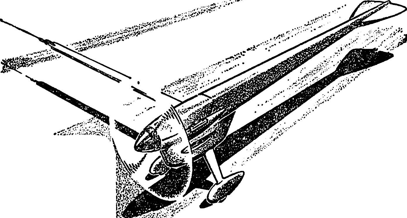
Fig. 4. Racing the car with a propeller:
1 — tail wheel, 2 — regulator, 3 tail beam, 4 — fairing of the engine, 5 — cover, 6 — rush motor, 7 — latch, 8 — Kok air like, 9 — th, 10 — fairing main landing gear wheel, 11 — cord strap.
The quantity “a” and “b” to pick up in the process of balancing the car.
The exhaust window is conventionally shown on the right side.
Fig. 5. The front wheel fairing:
1 — front chassis (D16T with a thickness of 2-2,5 mm), 2 — spinner wheels (lime or stamping from a sheet of celluloid of a thickness of 0.8 mm, to glue the ua Desk), 3 — the disk-nut (D16T, thread М6Х0,5), 4 — M3 nylock nut, 5 — washer (steel), 6 — tire (polyurethane), 7 — axis-rivet with a threaded shank M3 (semi-steel), 8 — disk (steel, thread external М6Х0,5).
* — the size in a tightened condition.
Locking discs relative to each other — the three “dots” marking drilling position. On the surface, facing the bus, turning operations to inflict a series of concentric grooves with a depth of 0.3—0.4 mm, which increases the reliability of the clip “spikes” between the discs.
Fig. 6. Design cord slot car racing with a propeller:
1 — the housing Board (pine section 2X34 mm, to the caudal end of the body section to reduce the 1X12 mm), 2 — (Lipa 4X4 mm), 3 — frame (plywood 1.5 mm), 4 — fuel tank (maximum capacity of 30 cm3 , soldering of tinplate thickness 0.2 mm) 5 — motor mount (white hornbeam), 6 — plate motor (lip thickness of 4 mm), 7 — a cover (lime hollow), 8 — “Cup” fairing (D16T), 9 — Kok-nut (D16T), 10 — fairing of the engine (balsa or foam PVC), 11 — landing gear (wrap the yarn, gluing in children. 10), 12 — fungi with internal thread M3 (steel, gluing in children. 5).
So, the main factors of the movement of micromachines defined. Try on that basis to design racing with a propeller. As one of the possible variants of the proposed design, shown in figure 4. Its advantages: good stability at distance, minimum weight, simple and therefore, reliable (and lighter) power circuit, the minimum number of parameters subject to adjustment during the training sessions, and finally a small wetted surface.
Furthermore, the detailed understanding in matters of suspension, to ensure the stability of the course and sustainability of start-up and running at maximum speed on track of any quality.
We note again that the result of “scientific research” model is simpler both in design and in manufacture. Hence its reliability is improved. So, the chosen search path was correct.
It remains to add: “space materials and technologies, available units, now you do not need. Appears the possibility of a full production of a model by the boys with virtually no professional (I) machining of parts.
E. GOROV, design engineer, group leader
Recommend to read REDUCER WITH CLIP A five-liter cylinders for portable gas stoves are easy to use, but to exchange them for sometimes full and not empty. The fact that the wear of the valve stem from the old container for... ALMOST LIKE IN THE CITY! Having started setting up the household on a neglected dacha plot, I installed a cabinet with a sink in the kitchen. I hung a washbasin and placed a bucket underneath for drainage. This... 
 All have long been accustomed to the fact that kordovye the car with a propeller is the most simple among the racing: case-stick, four knife-like wheels yeah the pylon model airplane engine. As it should be. This class is designed for beginners, his task is to instill in children the skills of working with tools and different materials, to give the opportunity in the first year of classes to partake of the excitement of wrestling competitions.