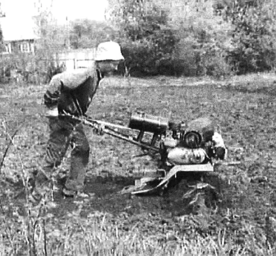
Almost a decade ago, I purchased a house with a garden plot in a village. The plot needed to be cultivated, but without machinery, this work was overwhelming, and there was no money left for it. So I was forced to build a walk-behind tractor for this purpose.
I already had experience in amateur construction by that time — again, for trips to the village in winter, I made a “stick” snowmobile (with a belt-bar track). Although I had seen quite a few walk-behind tractors (both industrial and homemade), I was building one myself for the first time, so I did much of it by intuition. In my estimates, the walk-behind tractor was also supposed to become a vehicle for those same trips, and a cargo one at that, even an all-terrain vehicle, since part of the way to the village was a dirt road that could only be called a road with great stretch.
Looking ahead, I note that the design turned out to be quite successful: simple and reliable. Later, I myself built several similar walk-behind tractors to order, and other craftsmen, including guys from our “Modelist-Konstruktor” club, used it as a model when building their machines. When preparing the publication, I used photographs of several of them, so the execution of individual units may not match the original design. But it can be used by those who want to replicate the design in their own version.
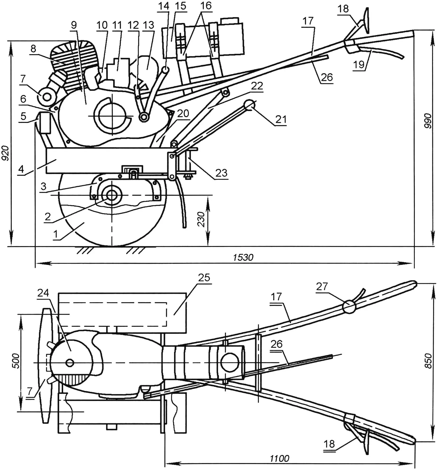
1 — wheel (from “Kaskad” walk-behind tractor, 2 pcs.); 2 — drive shaft; 3 — reducer (from “Muravey” motor scooter); 4 — engine frame (two channel bars No.12 welded lengthwise); 5 — headlight; 6 — front bracket for mounting engine to engine frame; 7 — muffler; 8 — engine cylinder (from “IZH-Planeta-3” motorcycle); 9 — engine crankcase (from “IZH-56” motorcycle); 10 — reed valve; 11 — carburetor; 12 — gear shift lever; 13 — air cleaner; 14 — starter lever; 15 — fuel tank (from fire extinguisher); 16 — brackets for mounting fuel tank on steering levers; 17 — steering levers (steel tube Ø27, 2 pcs.); 18 — rearview mirror; 19 — clutch lever; 20 — rear bracket for mounting engine to engine frame (steel, sheet s4); 21 — reverse engagement handle; 22 — brace (2 pcs.); 23 — kingpin of the towing hitch; 24 — forced air cooling system housing for cylinder (fiberglass); 25 — fender-mudguard; 26 — gear shift rod (ski pole); 27 — throttle grip
There were no problems with choosing the power unit — I had a not new, but quite serviceable engine from an “IZH-Planeta-3” motorcycle. I once bought it “in a bag,” disassembled into parts, but overhauled and assembled it. Of course, it could no longer provide the design power of 18 hp, as its cylinder was already quite worn, but it still delivered 15-16 hp. To be honest, that was more than enough. I started “dancing” from it, as they say, although I didn’t make any major modifications to it, except for equipping the cylinder with forced air cooling. Later, I replaced the valve with a reed valve — with it, the engine characteristics changed for the better — starting became easier, traction noticeably increased, fuel consumption decreased, and the engine itself ran smoother and quieter.
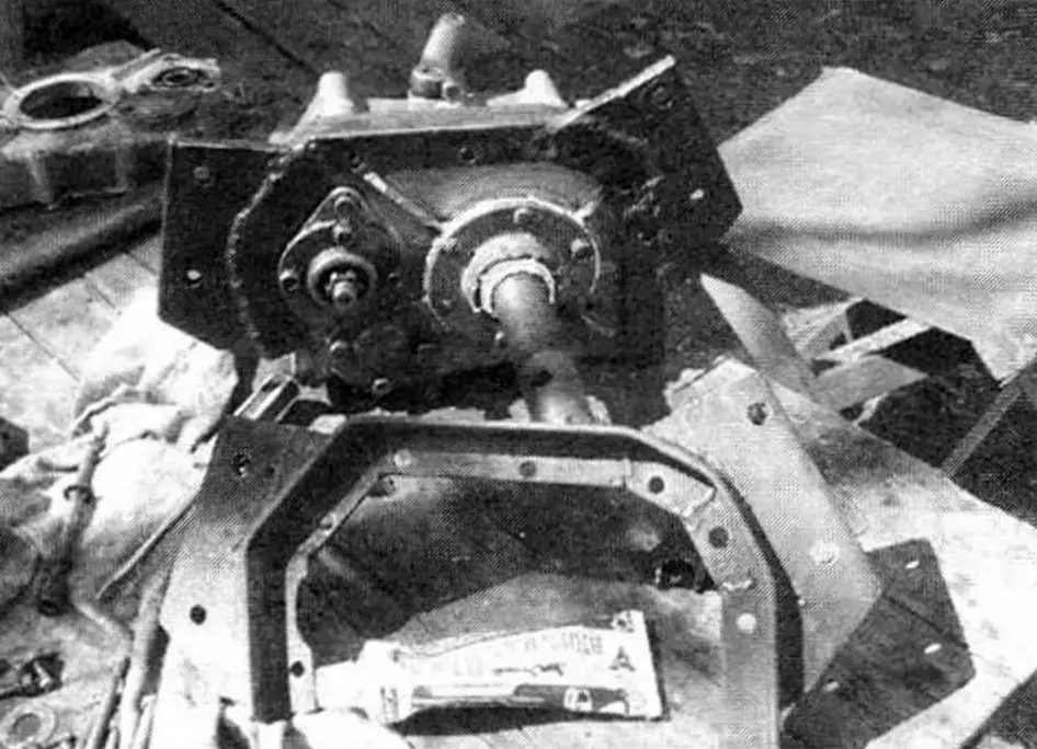
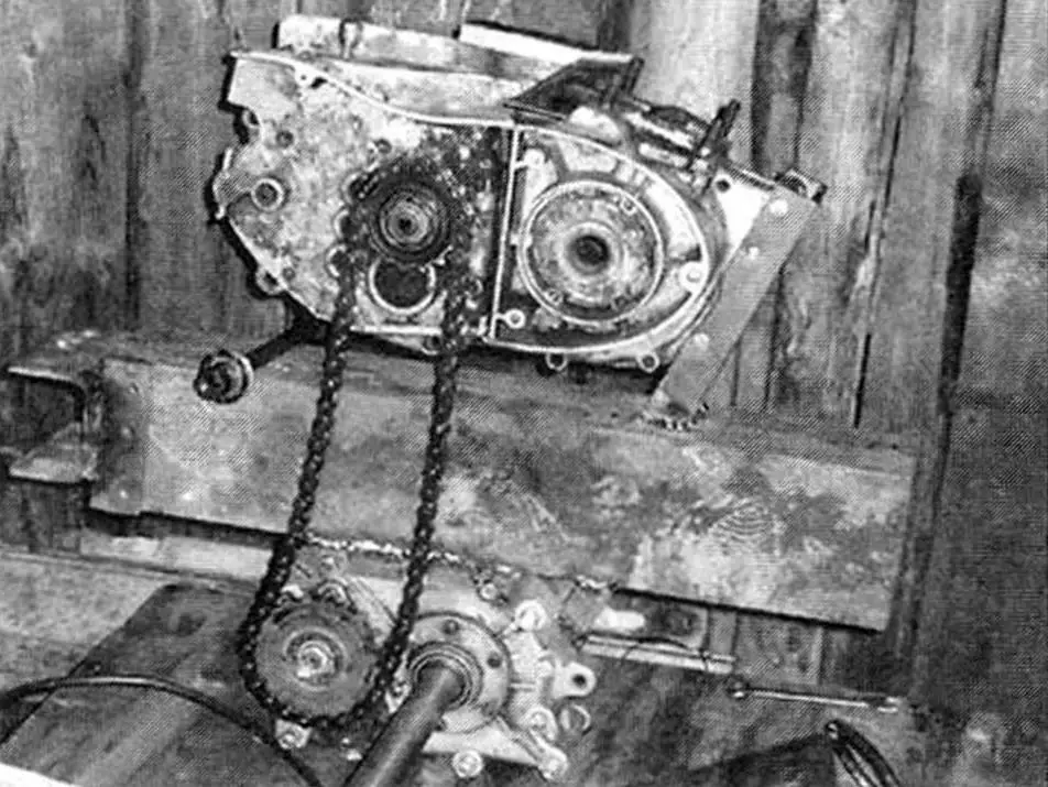
Another unit had to undergo significant reconstruction — the reducer. I used it together with the final drive from a cargo motor scooter “Muravey.”
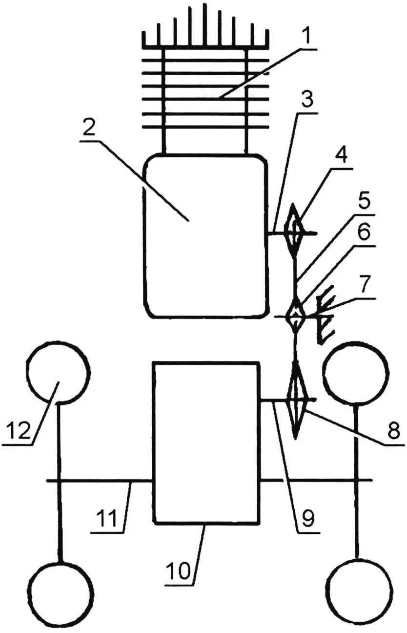
1 — engine (from “IZH-Planeta-3” motorcycle); 2 — gearbox (GB) of the power unit; 3 — secondary (output) shaft of GB; 4 — output sprocket of GB (standard “IZH-Planeta-3”); 5 — transmission chain; 6 — tension sprocket (nylon, from agricultural machinery); 7 — tension sprocket axle; 8 — reducer input sprocket; 9 — reducer input shaft; 10 — reducer (from cargo motor scooter “Muravey”); 11 — wheel drive shaft; 12 — wheel (from “Kaskad” walk-behind tractor)
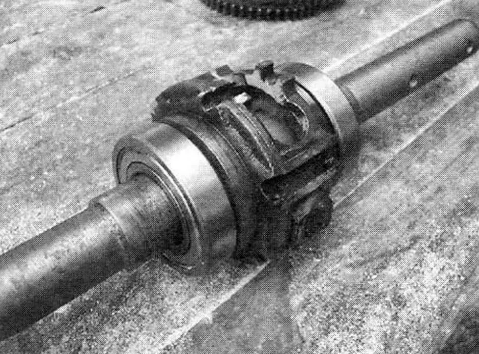
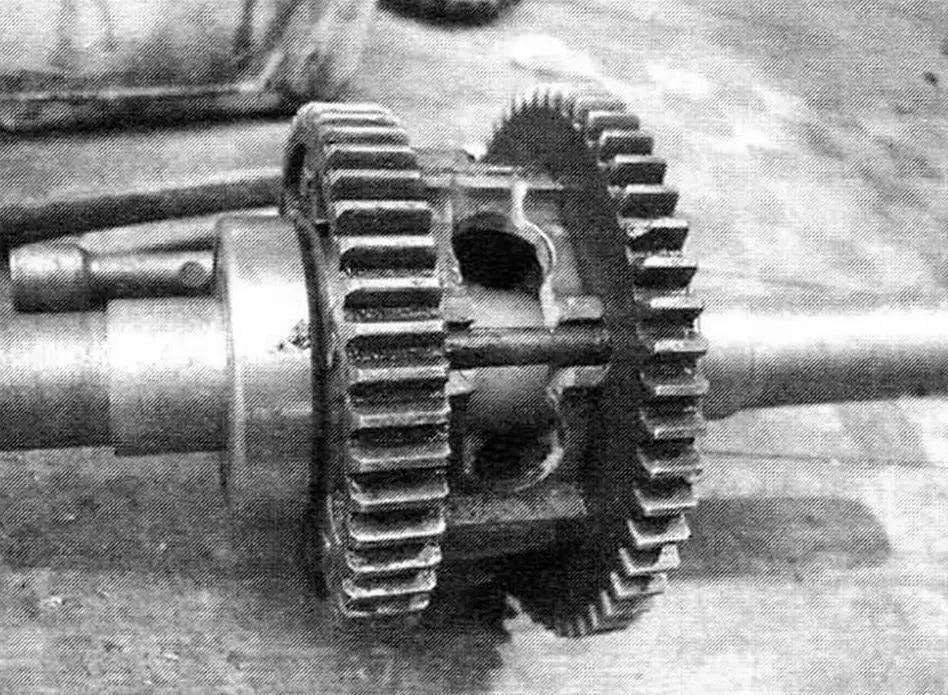
First, I removed the satellites from the differential cup. I expanded the cup windows by cutting the bridges between adjacent pairs of existing windows with welding. I mounted the differential cup on the shaft and welded one part to the other through the expanded windows.
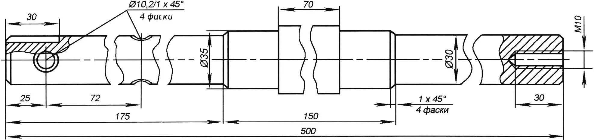
Second, I turned a drive shaft with a main diameter of 30 mm for mounting cutters or wheels with journals in its middle part for bearings 207 (I replaced them with 80207 — with side protective washers). At the ends of the shaft, together with the wheel hubs, I drilled holes into which I inserted cylindrical keys — as it turned out, under intensive and heavy operation, the diametral bolts securing the wheels on the shaft don’t hold — they get sheared. In the shaft ends, I made threaded holes (sockets) M10, into each of which I screwed a bolt with an expanded washer — it prevents the key from falling out. I should note here that the wheels are from the industrial “Kaskad” walk-behind tractor. For tillage work, I install tubeless (gusmatik) wheels size 5.00-10″, and for transport — pneumatic 6.00-12″.
Third, I cut off the protruding ears-bushings from the reducer crankcase that extended beyond its halves. I “wrapped” the crankcase halves themselves on three sides (front, top, and rear) with reinforcement made of rolled steel angle with 30×25 mm flanges. I had to work on the reinforcement to fit it tighter, but now the duralumin crankcase itself is also strengthened.
I moved the shaft with sprockets from the left side of the drive to the right. The mounting holes in the cheeks (flanges) of the reducer primary shaft almost match, except for some — they need to be drilled. This rearrangement could have been skipped, but it simplified the transmission and made it possible to do without an intermediate shaft.
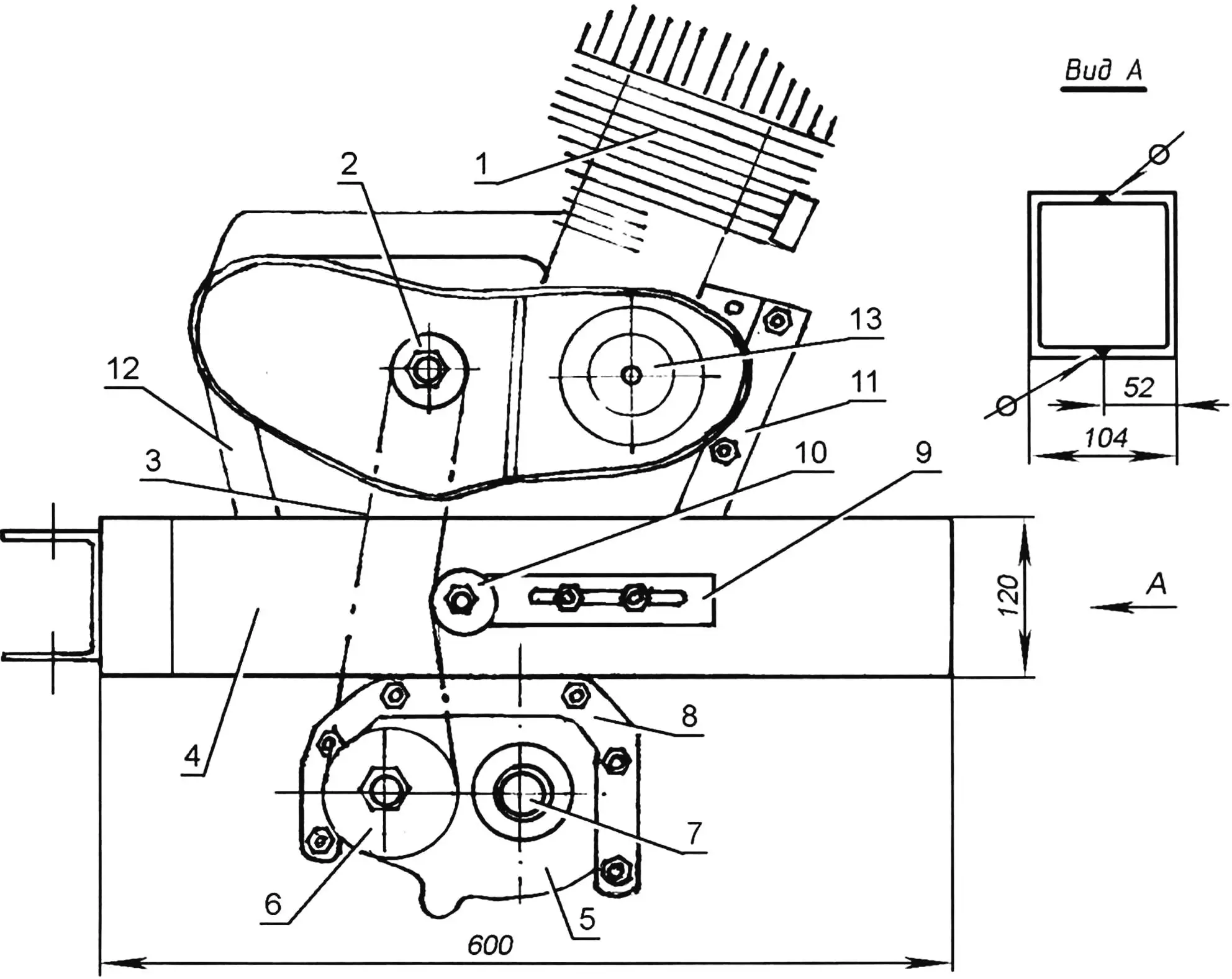
1 — engine; 2 — output sprocket of engine GB secondary shaft; 3 — chain (t= 15.875); 4 — engine frame; 5 — reducer; 6 — reducer drive sprocket; 7 — reducer drive shaft (steel, round Ø35); 8 — reducer reinforcement (angle 30×30, 2 pcs.); 9 — tension mechanism plate (steel, sheet s4); 10 — tension mechanism sprocket; 11 — front engine mounting bracket; 12 — rear engine mounting bracket; 13 — forced air cooling pulley attachment for engine
Then I moved on to laying out the relative positions of the power unit and reducer. But first, I made the engine frame (essentially, it also serves as the frame of the entire walk-behind tractor). The engine frame is a square-section tube 600 mm long, welded from two sections of channel bar No.12. On the engine frame, I placed the power unit crankcase on top, and attached the reducer crankcase to it from below so that the drive shaft was positioned approximately in the middle of its length. Since the distances from the symmetry planes of the engine and reducer are different, I had to shift the first one a dozen millimeters to the left (in the direction of travel). At the same time, I moved the engine crankcase forward on the engine frame to slightly increase the distance between the transmission sprockets and install another one — a tension sprocket — between them. At this point in the transmission (between the power unit and reducer sprockets), an intermediate shaft (sometimes called a “speed reducer”) could be installed to increase tractive effort. But on my walk-behind tractor, an acceptable overall gear ratio is “derived” through the use of a gearbox from “IZH-56,” and the engine power is already in excess.
After checking the relative positions in one plane of the power unit output sprocket (sprocket of the power unit GB secondary shaft) and the reducer input sprocket, I welded the crankcase half reinforcements to the engine frame, and for mounting the power unit on the engine frame — bracket-ears made of 4-mm steel sheet, bent in the shape of a stamped channel bar. I installed the engine crankcase on the engine frame, fitted it, and welded the brackets to it. I drilled mounting holes in the brackets on site. Actually, if oblong slots are made in the engine crankcase mounting brackets instead of regular holes, then the tension sprocket can be dispensed with, and the chain can be tensioned by shifting the engine relative to the engine frame, simplifying the transmission design.
After laying out the main units, I proceeded to design the remaining mounts: control levers, towing and attachment devices. The control levers (made from thick-walled tube with outer diameter 27 mm) are bolted to the rear bracket for mounting the power unit and supported by braces. And on the levers themselves, I later mounted the fuel tank on stands. At the rear, I welded a drawbar to the engine frame — part of the towing hitch of the walk-behind tractor with the cart. The drawbar serves for mounting tillage implements: plow, cultivators, etc. At the front, I welded a pin to the engine frame for mounting ballast plates that increase traction on a muddy dirt road or with the soil when cultivating plantings on the plot.
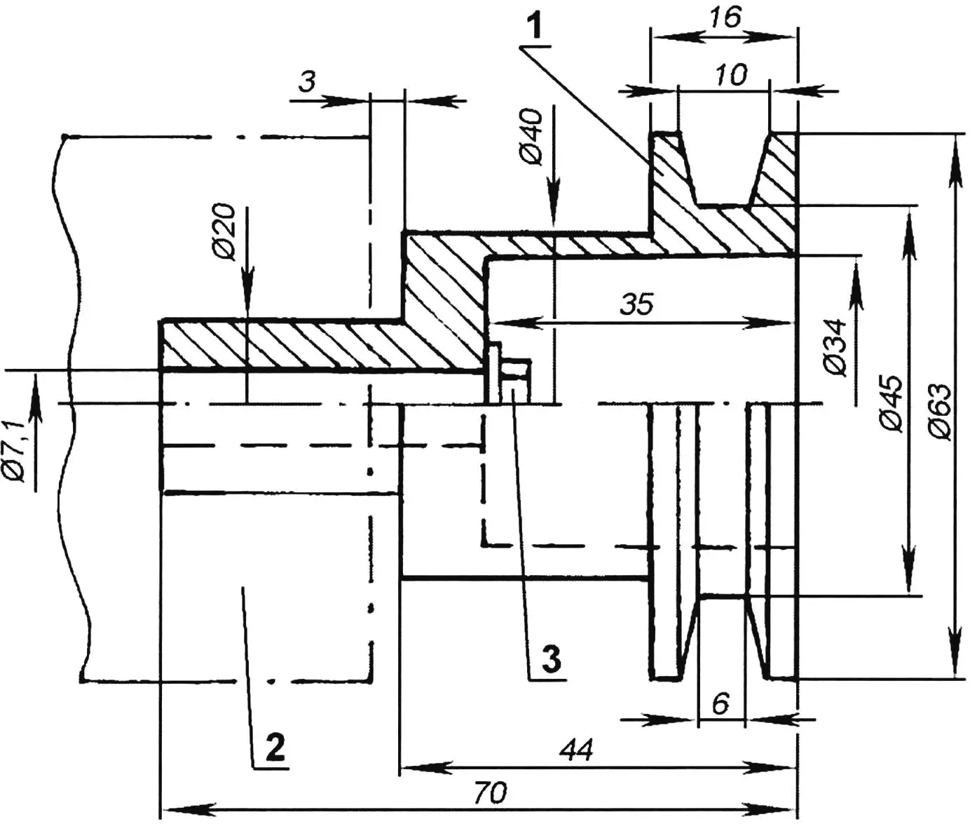
1 — pulley attachment (steel, Ø 63); 2 — generator; 3 — M7 bolt for mounting pulley attachment to generator armature
As noted at the beginning of the article, I equipped the engine cylinder with forced air cooling. The centrifugal-type impeller is from a UAZ car cabin heater. The impeller drive is through a belt drive with pulleys with a gear ratio of 1. The drive pulley is mounted on the generator rotor. As a belt, I used a rubber ring (“passik”), cut from an “IZH” motorcycle tube — it doesn’t require tension and is easily removed to disconnect the drive in cool weather. I molded the housing from fiberglass on epoxy binder over a pre-made wire frame. It (the housing) is quick-release, secured to the cylinder with two springs. But I must admit that the impeller doesn’t fully provide cylinder cooling under extreme conditions when moving in lower gears, so I plan to replace it.
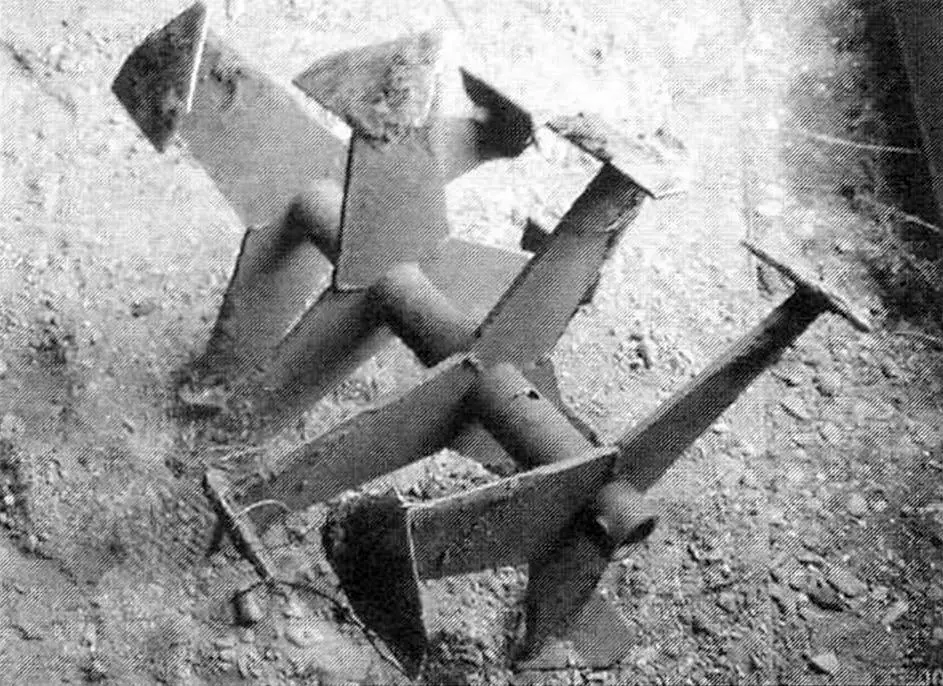
I didn’t make the cutters (there are two of them) myself either, but, like the wheels, I bought factory-made ones, “arrow-shaped,” or, in other words — “goose feet” — they are made at the local Perm plant for the “Kaskad” walk-behind tractor. The cutter hubs are thick-walled tubes with an internal diameter of 30 mm — they fit onto the shaft of my walk-behind tractor without modification — after all, I turned the shaft for them. The cutters are secured on the shaft with two bolts each, through corresponding through holes in both parts. The sweep diameter of the cutters along the “arrows” is 350 mm. Each is equipped with four rows of tines (three tines per row). And I must note that I was satisfied with these cutters: they don’t crush weeds, but throw them to the surface (though they sometimes wrap around), don’t dig into the ground, and run smoothly. I even conducted such an experiment: I let a running walk-behind tractor go into “free sailing” along a 50-meter section, and it independently plowed (cultivated) normally without turning anywhere. Designs of similar, but homemade cutters have been shown more than once on the pages of the “Modelist-Konstruktor” magazine, so I’m only giving their photographs, without a drawing. The working width during cultivation with shaft extensions is up to 900 mm.
Besides “arrow-shaped” cutters, I adapted ready-made or made other tillage implements: a small plow, a hiller, a cultivator, a potato digger.
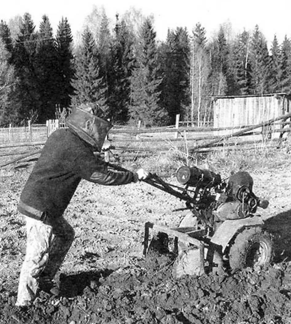
The minimum speed of the walk-behind tractor is about 5 km/h. At this speed, I perform plowing, cultivation, and dig potatoes.
I installed electronic ignition on the engine — from a “Voskhod” motorcycle. I equipped the walk-behind tractor with a road headlight.
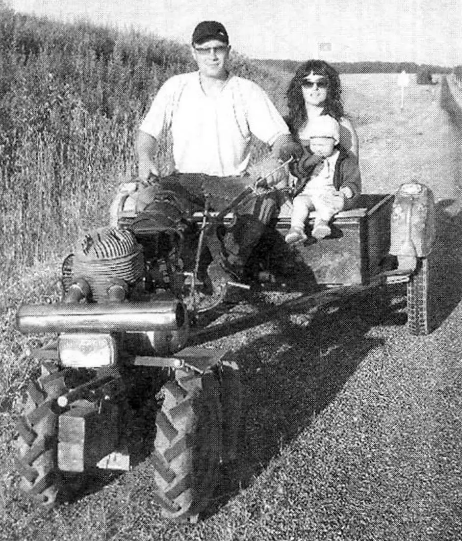
Since the walk-behind tractor was conceived from the start also as a motor tractor, I made a towed cargo single-axle cart with a body with a load capacity of up to half a ton and a two-seat seat. Making a soft sofa with a backrest wouldn’t have been much trouble either, but then it wouldn’t be possible to transport long loads, and sometimes I have to transport logs up to six meters long. However, the backrest can easily be made removable. The trailer tongue is made from a rectangular tube with a cross-section of 50×40 mm with 2.5 mm walls. It is reinforced with two more braces made from equal-flange angle No.4.
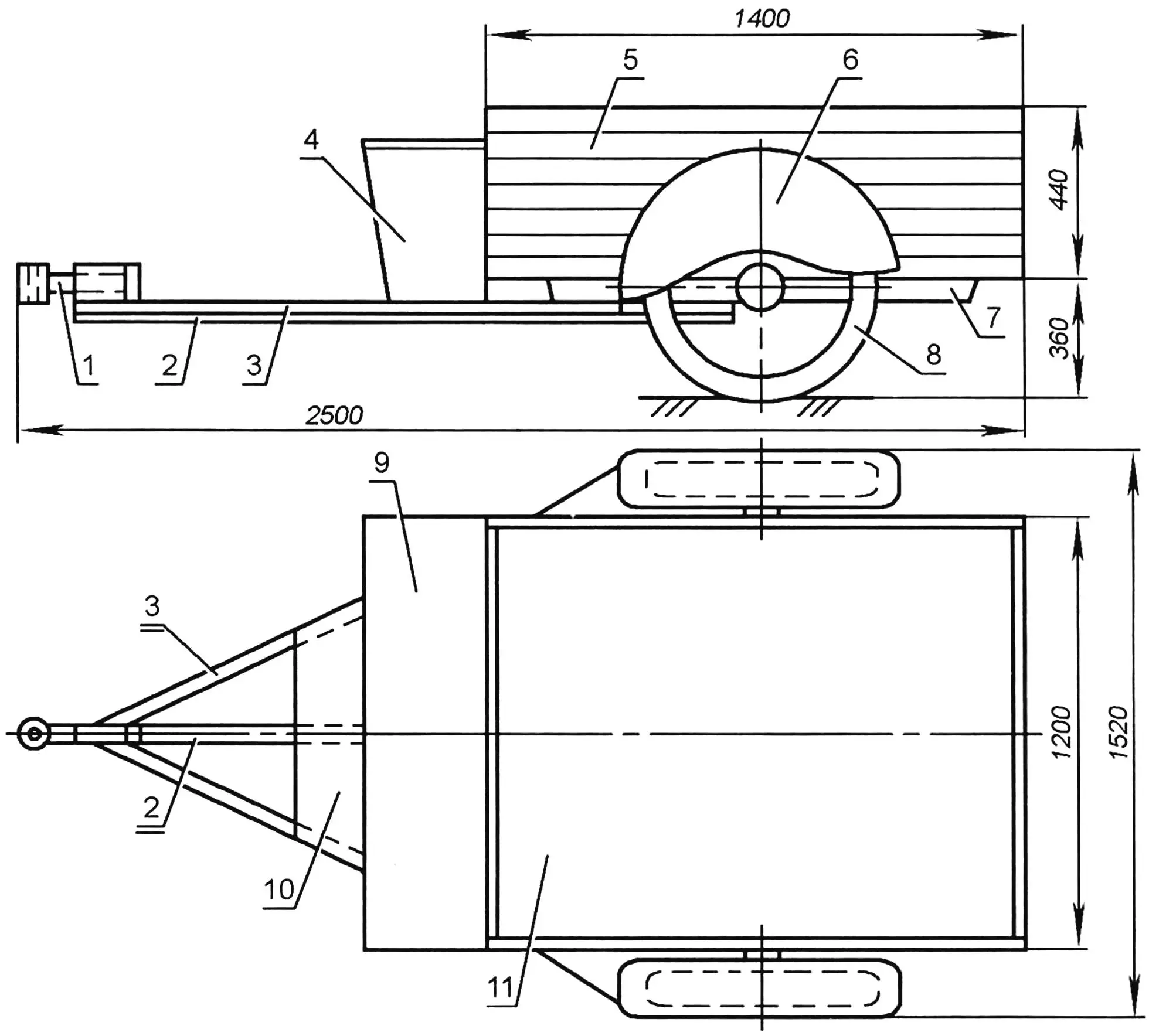
1 — towing hitch; 2 — tongue (steel tube 50×40); 3 — tongue beam (steel angle 40×40, 2 pcs.); 4 — trunk (steel sheet s1.5); 5 — body (tongue-and-groove board s16); 6 — wheel fender (from “IZH-56” motorcycle); 7 — body frame (from “IZH-56” motorcycle); 8 — cart wheel (from “IZH-56” motorcycle); 9 — seat-trunk lid (board s20); 10 — floor (board s20); 11 — body floor (steel sheet s1)
The towing hitch is simple but reliable, of the kingpin type. The cart body with plan dimensions of 1200×1200 mm is wooden, the sides are made from tongue-and-groove board 16 mm thick, the floor is made from “twenty” board and sheathed with 1.5-mm steel sheet.
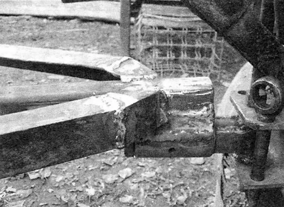
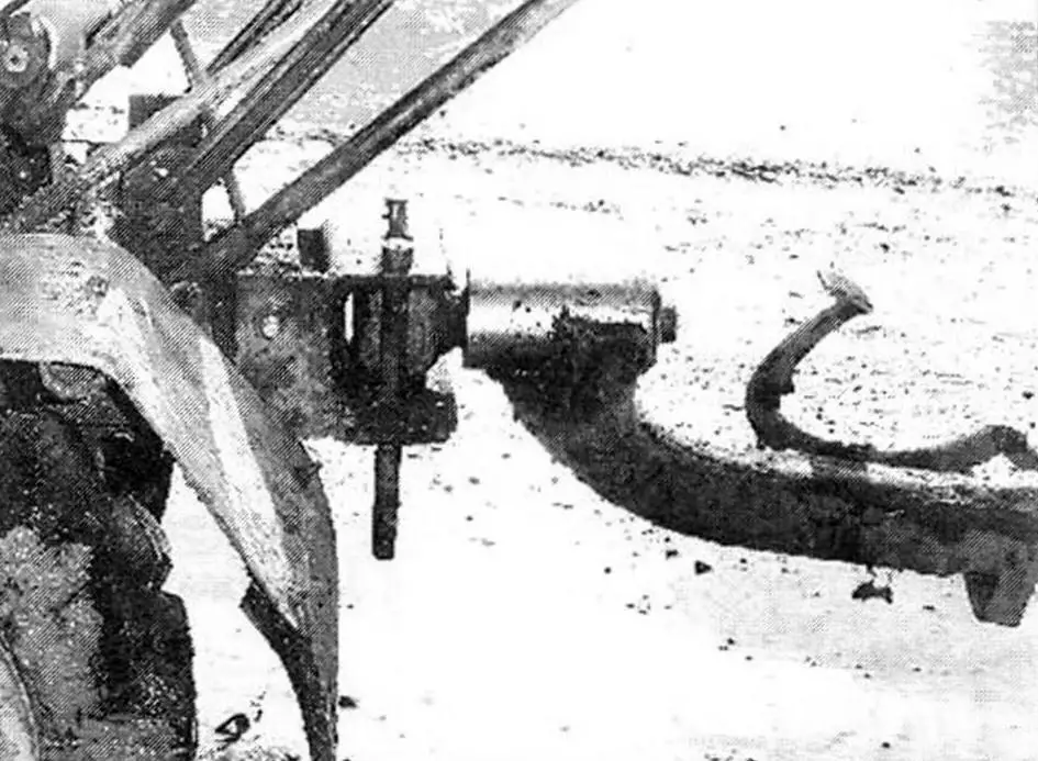
The cart chassis with a wheel track of 1500 mm is assembled from two side trailers from an “IZH” motorcycle. The wheels are also from it. Their suspension is torsion, soft, so traveling 60-70 km on the “walk-behind tractor — cart” tandem on a relatively smooth field road is not difficult. Up to a speed of 50 km/h, the tandem is obedient in handling. Per season, I put 3-4 thousand kilometers on it for various tasks: to the forest for firewood, to the field for hay (I just haven’t “taught” it to mow yet) and for fishing. A very important unit of the trailer and walk-behind tractor is the towing hitch. Its design can be different, but reliable. It should also allow the trailer to turn relative to the walk-behind tractor not only in the horizontal plane, but also in a limited vertical sector, so that the cart wheel doesn’t hang up. The total length of the towed cart is 2.5 meters.
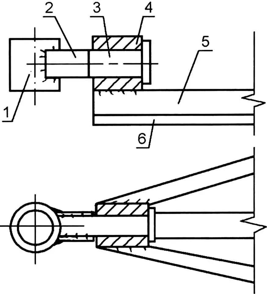
1 — kingpin bushing (tube Ø50×30); 2 — plate (steel sheet s4, 2 pcs.); 3 — swivel (steel, round Ø45); 4 — swivel bushing (tube Ø50×30); 5 — tongue beam; 6 — tongue
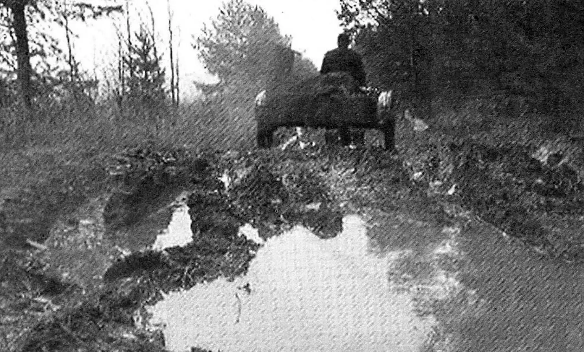
Thanks to the engine power, locked wheels, shod with tires with large “herringbone” tread, and speed qualities, the walk-behind tractor with the towed cart turned out to be a high-mobility machine, so I operate it from early spring to late autumn. In some road (or rather — off-road) situations, the reverse gear that appeared thanks to the reducer also helps. The wheels on the shaft, or rather their hubs, are secured with two bolts. But from merciless operation of the walk-behind tractor, the bolts were repeatedly sheared. Therefore, I additionally secured them from turning on the shaft with longitudinal cylindrical keys.
The walk-behind tractor became an indispensable helper in the garden plot and in the household in general.
During operation, I only overhauled the reducer: the bearing play increased. And I regretted even that — I could have ridden for two more seasons.
R. AKHMETZYANOV
Recommend to read
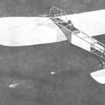 ABOUT HOW MODEL AIRCRAFT DID
Any machine is not born suddenly starts with something more simple. It happened with the plane-monoplane. Its forerunner was destined to become a flying model. Was 1887. Professor of...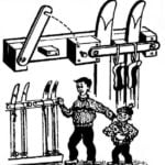 “HANGER” FOR SKIING
If the family and children, and the parents are addicted to skiing, it makes sense to find the area for neat and easy storage. The easiest way to arrange a wall "hanger" ski rack, which...
