
The two-seater velomoto car “Tandem” — my latest homemade design with a combined drive: from the pedals of the driver and passenger (in this case, he becomes the second crew member), and a two-stroke moped engine D-6 with a displacement of 50 cm3 and a power of 1.2 hp (maximum number of revolutions — 4500 per minute).
The front steering wheels are reinforced from the “Kama” bicycle, and the rear drive wheels are from the “Ural” bicycle, modified (with widened hubs).
The source material for the “Tandem” was a velomobile, the description of which was already given in “M-K” No. 7 for 2008.
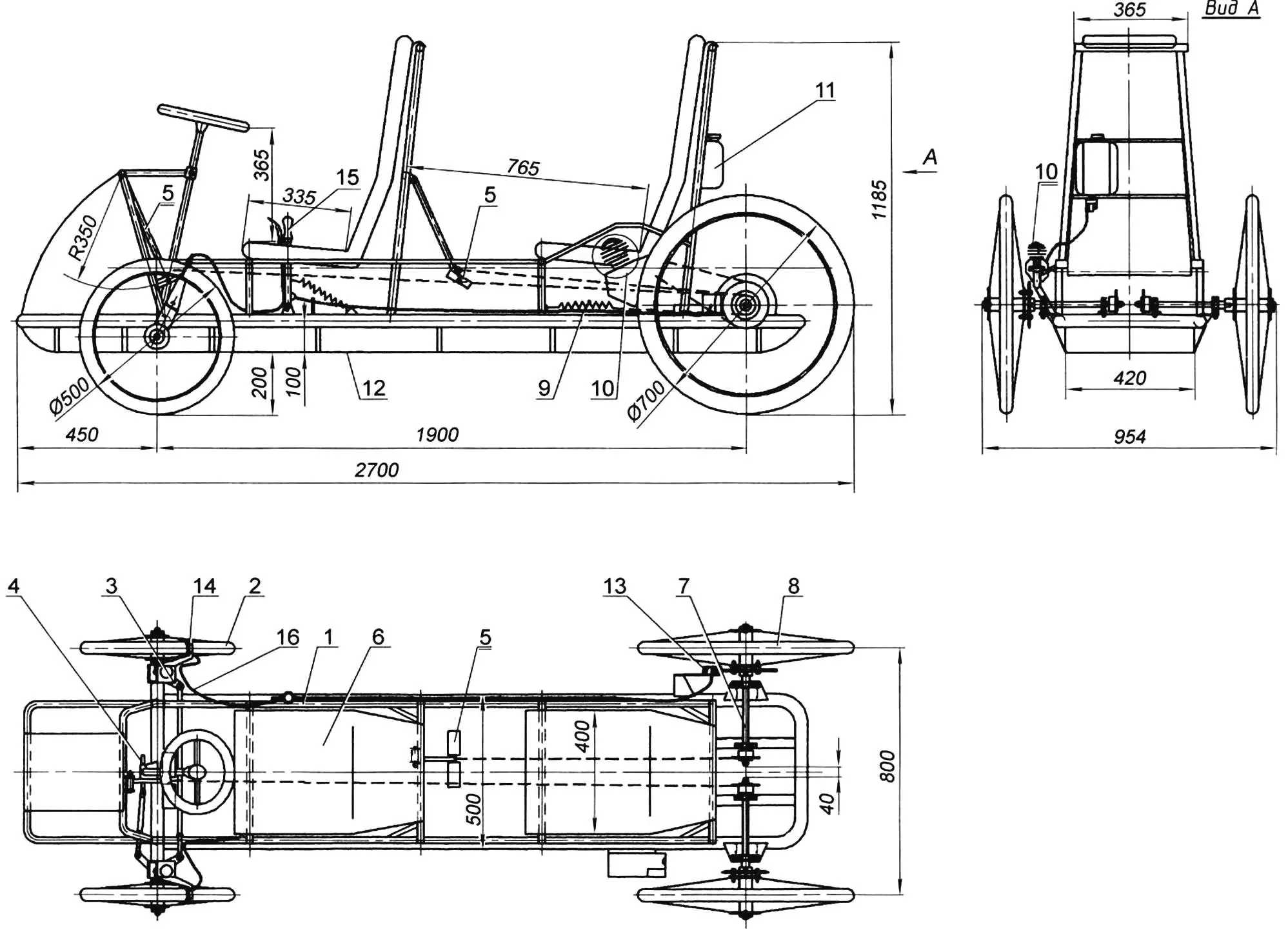
1 — frame; 2 — front wheel (from “Kama” bicycle, 2 pcs.); 3 — front wheel steering knuckle (2 pcs.); 4 — steering mechanism (rack with tie rods); 5 — pedal unit (2 pcs.); 6 — seat (2 pcs.); 7 — rear wheel half-axle (2 pcs.); 8 — rear wheel (from “Ural” bicycle); 9 — spring and cable for pedal drive return stroke (2 pcs.); 10 — D-6 engine; 11 — fuel tank; 12 — floor (duralumin sheet s1.5); 13 — rear wheel disc brake; 14 — front wheel caliper brake (2 pcs.); 15 — brake and engine “throttle” control lever; 16 — brake cable
The frame of the new velomobile is of truss construction (in the shape of a trough). Welded from round thin-walled tubes from handrails of a decommissioned bus and bed frames. It consists of two tubular side members, a front arc-bumper, a front beam-axle, a rear beam, several arc-shaped cross members, and a pair of rear longitudinal connections-supports for the half-axle ends. The side members are made from a tube with an outer diameter of 40 mm as one part in the shape of an arc converging at the rear. In the front part, a front axle beam made from the same tube is welded to the side members. Steering knuckle bushings are welded to the beam ends.
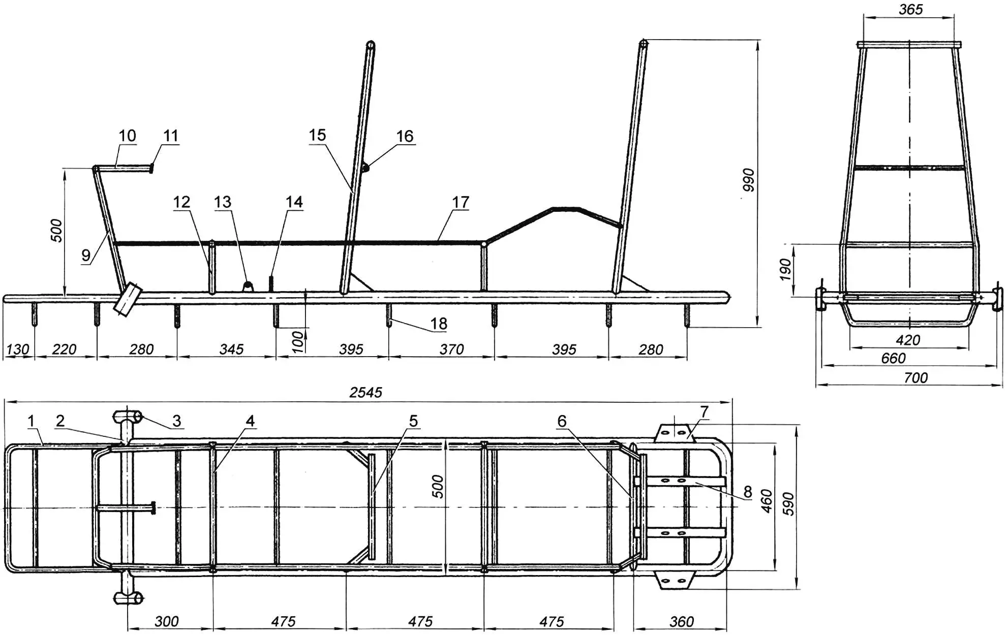
1 — bumper (steel tube Ø20); 2 — cross member (steel tube Ø40); 3 — steering knuckle bushing (steel tube Ø40, 2 pcs.); 4 — seat support (steel tube Ø20, 2 pcs.); 5 — seat back cross member (steel tube Ø40, 2 pcs.); 6 — half-axle longitudinal support cross member (steel tube Ø30); 7 — half-axle bearing 203 housing support platform (steel sheet s4, 2 pcs.); 8 — half-axle bearing 202 housing longitudinal support (steel rolled angle 32×32, 2 pcs.); 9 — under-steering portal (steel tube Ø20); 10 — console (steel tube Ø20); 11 — steering shaft mounting plate (steel sheet s4); 12 — seat support post (steel tube Ø20, 4 pcs.); 13 — engine and brake control lever mounting lug (steel sheet s4); 14 — brake cable mounting post (steel tube Ø15); 15 — seat side post (steel tube Ø20, 4 pcs.); 16 — pedal crank suspension lug (steel sheet s4, 2 pcs.); 17 — parapet (steel tube Ø20, 2 pcs.); 18 — arc-shaped cross member (steel tube Ø20, 8 pcs.)
An arc-bumper and a forward-tilted under-steering portal are welded to the front beam (later the space between them is covered with a duralumin fairing, under which a luggage compartment is located). A steering column console with a plate at the end is welded to the portal. All listed parts are made from half-inch tube. Several arc-shaped cross members between the side members, giving the frame a “trough” shape, are also made from the same tube. A floor made of 1.5 mm thick duralumin sheet is laid on them.
Along the frame on the sides, parapets are made from thin-walled tubes with an outer diameter of 15 mm, which turn into handrails near the seat of the rear (second) crew member. It is convenient for him to hold onto them when pedaling, and simply when riding — he has no steering wheel.
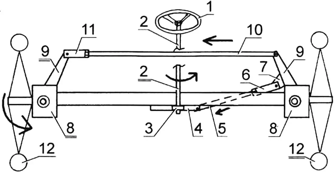
1 — steering wheel; 2 — steering shaft; 3 — steering mechanism gear; 4 — steering mechanism rack; 5 — short tie rod; 6 — short tie rod length adjustment threaded bushing; 7 — short tie rod to steering knuckle lever mounting lug; 8 — steering knuckle (2 pcs.); 9 — steering knuckle lever (2 pcs.); 10 — long (inter-wheel) tie rod; 11 — inter-wheel tie rod length adjustment threaded bushing; 12 — front steerable wheels (2 pcs.)
The frame elements also include low U-shaped seat support posts for the driver and passenger, as well as high support posts for their backs, made in the form of trapezoidal portals. Both types of posts rest on the side members and connect them.
The seats themselves, more precisely, their bases, are made from 1.5 mm thick duralumin sheet (by the way, the floor and front fairing are also made from the same sheet). The seat cushions and their backs are made as a single unit from 50 mm thick foam rubber and covered on top with light leatherette.
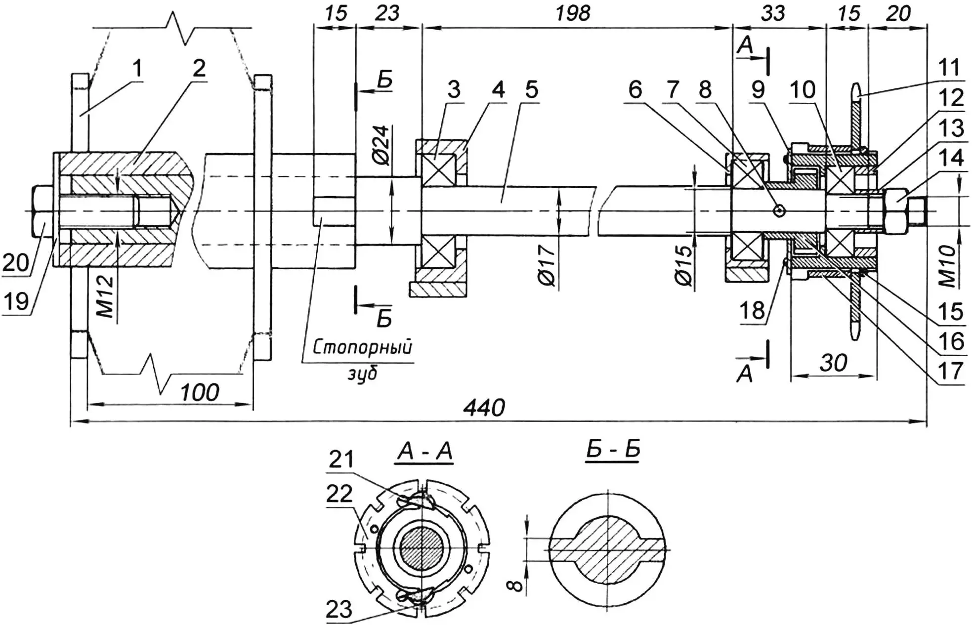
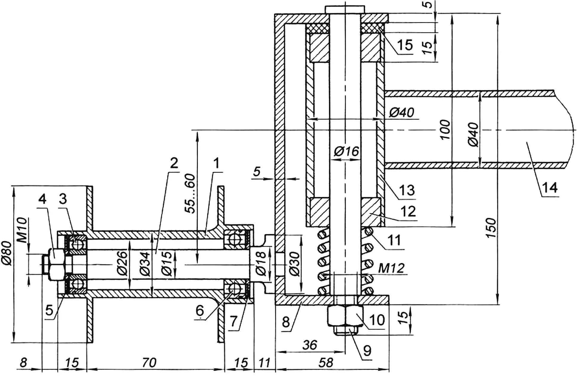
1 — rear wheel; 2 — rear wheel hub; 3 — bearing 203; 4 — bearing 203 housing; 5 — half-axle (steel 45, round Ø24); 6 — bearing 202 housing; 7 — bearing 202; 8 — pin (steel 45, round Ø4); 9 — cover; 10 — bearing 201; 11 — sprocket (from KhVZ bicycle); 12 — pressed locking bushing; 13 — thrust bushing; 14 — M10 nut; 15 — locking ring; 16 — ratchet (from KhVZ bicycle); 17 — spacer bushing; 18 — M4 screw (4 pcs.); 19 — thrust washer; 20 — M12 screw; 21 — pawl (from KhVZ bicycle); 22 — sprocket hub; 23 — return spring
The rear axle consists of two half-axles rigidly mounted on the frame (without suspensions), which to a large extent ensured the simplicity of the design. Each half-axle has two bearing supports, the housing of one of which is mounted on a platform welded to the side member, and the other — on an additional longitudinal support made from a 32×32 mm angle.
The front wheel suspension is on springs fitted on the steering knuckle axles. But since the suspension travel is quite small, to soften impacts from significant road irregularities, bump stops made of soft rubber are also installed on the upper ends of the axles.
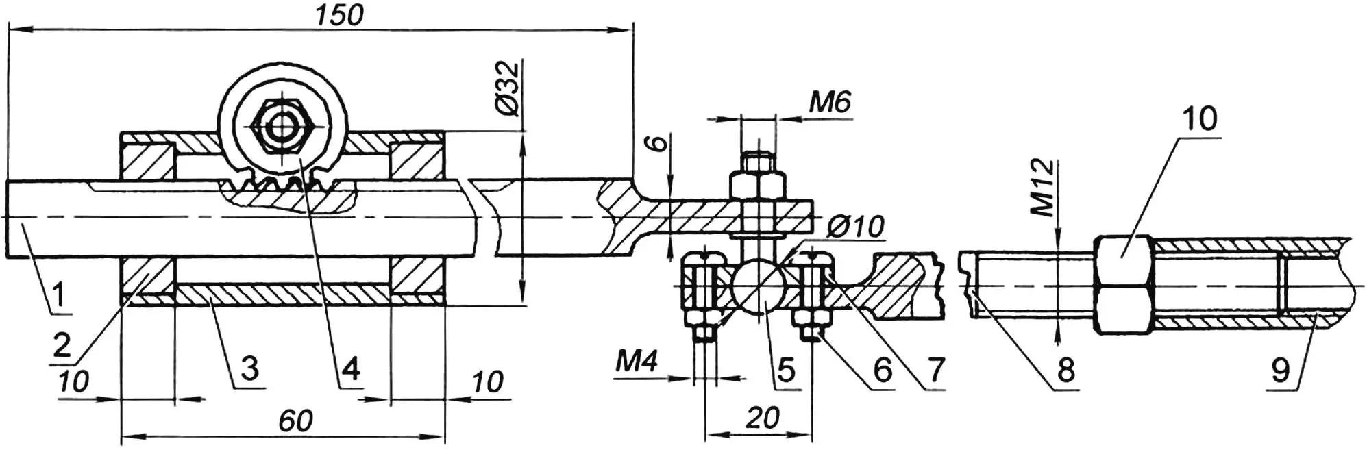
1 — rack; 2 — bushing (bronze, round Ø28, 2 pcs.); 3 — housing (tube Ø32); 4 — gear; 5 — ball pin with M6 nut; 6 — M4 bolt (4 pcs.); 7 — cover; 8 — tie rod with threaded M12 tip; 9 — short tie rod length adjustment threaded bushing (tube Ø16); 10 — M12 lock nut
Each crew member has a rocking (pushing) drive with a pair of opposed pedals and a chain drive to one wheel: from the driver — to the left, from the passenger (second crew member) — to the right. The paired pedals allow crew members to work (press the pedals) with both feet in difficult conditions. The chains and sprockets are bicycle-type with a pitch of 12.7 mm. The number of sprocket teeth is z=24. The chain length is only slightly longer than the pedal stroke (it is thrown directly onto the sprocket), and the chain is connected to the pedals by a 3 mm diameter steel cable. The return stroke of the pedals (and the chain with cable) is accomplished using a return tension spring (or, as is more commonly said, — normally compressed), mounted on the frame and connected to the chain.
As mentioned at the beginning, the velomobile also has a motor drive to the left wheel from a D-6 gasoline internal combustion engine. The transmission of rotation from it to the wheel is accomplished by a bushing-roller chain with a pitch of 12.7 mm. Chain tension is produced by a roller pressing the lower branch. The driven sprocket of the motor drive (wheel drive) has 46 teeth. Engine control, as well as velomobile control, is performed only from the first crew member’s position.
1 — front wheel hub housing; 2 — front wheel axle; 3 — bearing 201; 4 — M10 nut; 5 — outer dust cover; 6 — bearing 202; 7 — inner dust cover; 8 — steering knuckle bracket; 9 — steering knuckle axle; 10 — M12 nut; 11 — spring; 12 — bushing (bronze, 2 pcs.); 13 — steering knuckle bushing; 14 — front beam; 15 — rubber damper
A parking brake disc is mounted on the right wheel. It is actuated by a floor lever located under the driver’s right hand by moving “away from oneself”. When parked, it is moved forward and fixed. At the upper end of this lever is a manual lever-trigger for the main working caliper-type brakes acting on the front wheels. A moped-type sliding “throttle” grip is also located here, allowing fuel supply adjustment without having to hold it constantly. The clutch is disengaged by a pedal located under the driver’s right foot.
The steering control is of automotive type. It consists of a steering wheel with a tubular shaft, a rack mechanism, a short (from the rack to the left wheel) and a long (inter-wheel) tie rod, and steering knuckles. The steering shaft has two support points: at the bottom it is inserted into the steering mechanism housing, and a rack drive gear is mounted on it; at the top — it is secured with a clamp (with rotation capability) to the console plate of the under-steering portal.
A. MATVEYCHUK
Recommend to read
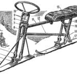 SNOW “THE LITTLE HUMPBACKED HORSE”
Snow scooter "the little humpbacked Horse" — advanced single track sled with steering from the mountains for skiing on-piste slalom or downhill. In different countries such sleds have... IN SEARCH OF PROFILE
The rocket plane with Delta wing design is widely known, repeated in dozens of models. However, leading athletes of the country are constantly experimenting, looking for even the...
