 No need to explain that the tractor to rural farmstead — the machine is not only needed, but necessary. As before the farm could not do without a horse, so now it can’t do without the tractor. Here only to purchase such equipment for those who most needed, that is a simple rural workers — as they say, can not afford.
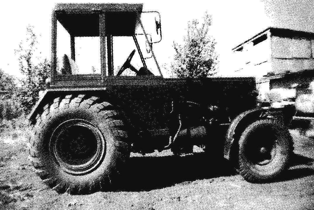
But if the owner — the man the workman, as the author niepublikowany article Mikhail Simonov from the village of Podsosenki the Balakovo district of the Saratov region, he can make the tractor itself. Literally from scrap Michael gathered such tractor, which is not inferior to similar machines industrial manufacturing, and not only its technical characteristics, but even in appearance.
Description made by M. Simonov tractor will start with the frame construction. Frame is pretty simple — symmetrical, almost square, and not even spatial. But all the units and components chassis: engine, transmission, suspension wheels — set on it though, and tight, but rationally.
The frame is welded. Its main force elements — a pair of side members (right and left) and traverse (front and back). The side walls are made integral, three-stage. Two front notches of the side members is made of channel No. 10 and the last of the square tube 80×80 mm. Front cross member is made of a channel No. 12, and the back of channel No. 16. Of channel number 12 another element of the frame cross member. A pair of sub brackets made of channel No. 8, but each of them is welded from two segments such that the shelf parts pointing in different directions. For the floor of the cab, outside of frame, welded frame made of rectangular tube 60×40 mm. the Frame is welded cantilever to the middle rungs spars with them outside of the place where they joined with the rear steps. This raznosortitsa in the gauge metal is caused not so much by constructive necessity, how much stock material.

Fig. 1. Geometric diagram of the tractor
On the frame are assembled chassis tractor mounted power unit, transmission, front and rear axles with wheels.
Power unit 4-cylinder diesel engine water cooling capacity of about 40 HP taken from decommissioned Bulgarian forklift (forklift).
Gear shift along with transfer case PTO shaft is used from the truck GAZ-53, and the clutch mechanism from the car GAZ — 52. To dock the clutch basket to the engine, had to weld a new cover of the basket and slightly alter the engine flywheel. On a lathe the flywheel trimmed back plane further and machined the center hole. When installing the parts that pre-deployed to 180°.
Used rear axle from a Bulgarian forklift without alterations. Suspension bridge there, and to the frame it is attached rigidly, by means of four ladders. Propeller shaft, though not long, had to make a composite. The rear part of the crossbar from a forklift, and front — GAZ-52. Connected of the shaft through a splined sleeve on the end of one part and slotted tip on the other.
Depreciation of the rear portion is carried out by 18-inch pneumatic tires of wheels borrowed from the all terrain vehicle GAZ-66. For planting these wheels on avtokraska hub of the disk cut out the middle part with mounting holes, and in its place was waril the same part of the disk from the wheel of the ZIL-130 — mounting holes correspond exactly to avtokraski.

Linkage with hydraulic lift allows you to connect any standard tillage operation, and the drag hook on the frame is a cargo truck

The tractor is a little different from brothers factory made. But moskovichevskoe lights give it the non-industrial fabrication
Front axle made. He’s not leading. Its design corresponds to that already repeatedly cited in the publications of homemade tractors in the journal “modelist-Konstruktor”. Front wheel hubs and wheels, used car GAZ-69.
But steering my tractor is not quite normal — hydraulic. It starts to work only when the engine is running, but much easier than a manual. Although the principle of operation is similar to avtokraski, the mechanism mostly homemade, using components and parts from different techniques.
The work of the steering equipment is provided with its own gear oil pump NSH-10, which is fixed to the engine and is driven by it.
The steering wheel along with a dispenser used from the harvester KSK-100A.
Where are usually the vehicles is the steering gear (e.g., pinion and rack) which controls the control rods on my tractor steering hydraulic cylinder. He improvised, double-acting — piston had one and rod two. The free ends of the rods connected to the tie rod end. Movement of the piston in the cylinder in one direction or another is ensured by the flow of oil under pressure from the dispenser, through one of the two fittings (alternate) embedded in the wall of the cylinder on opposite sides of it.

Fig. 2. Frame:
1 — front cross member (channel No. 12); 2 — step front spar (channel №10, 2); 3 — crossbar (channel No. 12); 4 — sub bracket (channel No. 8, 2 PCs); 5 — intermediate spar (channel No. 10,2 PCs); 6 — bars console underground (tube 60×40,2); 7 — rear stage of the spar (tube 80×80,2); 8 — rear (channel No. 16); 9 — fender liner (area 20×20, 2); 10 — resistant bracket joining portion (steel sheet s5. 2); 11 — bracket front axle

Fig. 3. Layout diagram of the chassis of the tractor:
1 — front wheel (GAZ-69, 2); 2 — radiator (from a Bulgarian forklift); 3 — the engine 4-cylinder, diesel, 40 HP (from Bulgarian forklift); 4 — clutch mechanism (GAZ-52); 5 — gear shift (GAZ-53); 6 — hand-brake; 7 — rear wheel (GAZ-66, 2 PCs.); 8 — linkage for mounting the tillage tools (tractor MTZ-80); 9 — PTO (farm equipment); 10 — rear axle (from a Bulgarian forklift); 11—propeller shaft; 12 — transfer box PTO shaft (GAZ-53); 13 — frame; 14 — front axle

Fig. 4. Front axle:
1 — wheel hub (GAZ-69, 2); 2 — steering knuckle (GAZ-69, 2); 3 — bushing knuckle (tube Ø77); 4 — beam axle (pipe and Ø70 Ø77)

Fig. 5. Diagram of hydraulic steering gear:
1—steering wheel (from the harvester KSK-100A); 2 — dispenser (harvester KSK-100A); 3 — high pressure hoses (from the farm); 4 — hydraulic cylinder; 5 — the pump NSH-10; 6 — oil tank (receiver truck tractor T-150)

Fig. 6. The hydraulic cylinder of the steering mechanism:
1 — the steering joint (2 PCs); 2 — tie rod (2 PCs); 3 — locknut M18 x 1 5 (2); 4 — stock (steel, circle 28, 2); 5 — Cup (steel, round 70, 2 pieces); 6 — threaded tap connector (G 1/2″, 2); 7 — cylinder body (tube 60×5); 8 — piston (steel, circle 50); 9 — bracket (steel, sheet s5); 10 — cuffs with snap rings

Fig. 7. Completion of engine flywheel: the shaded part is to grind
Two-way cylinder of the steering mechanism made of a conventional hydraulic cylinder from machinery. The cylinder was dismantled, blind flange cut off and bored through here thread under the same glass that’s on the other end of the cylinder. Here about carving in the wall punched another hose. The piston is upheld, only one of the cuffs turned. Stock slightly shortened, and the piston on the other side was attached through a threaded hole in one — homemade. At the free ends of the rods secured to the tie rod end from the GAZ-69. Cylinder Assembly secured to the front axle by two bolts M12.
The tractor has a separate hydraulic system which is connected to the power cylinder of the rear hitch control (lifting — lowering) agricultural implements. It is operated by a pump NSH-32, which is also installed on the engine. The power cylinder portion (like the hitch) — from the tractor MTZ-80.
Expansion oil tank 10 liters is made from the receiver dump truck tractor T-150.
The cabin is double, one-piece (top not removable), with large area of glazing, large side Windows with top hinge opens to the outside. The door one on the left side.
The frame of the cabin is welded from square tubes (20×20 mm and 40×40 mm) and rectangular section (40×20 mm) section. The door and the other side wall is lined with steel sheet thickness of 2 mm. the roof of the cab, and fenders (front and rear), bent from a single piece of 3-mm steel sheet. On the rear fenders for rigidity made frame and to the front is welded along the top arc of the longitudinal halves of the half-inch pipe. The frame of the hood is welded from the corner of 35×35 mm and lined profile steel sheet thickness of 2 mm. In the front of the hood are mounted two spotlights from the “Moskvich-2140”. Rear signal lights— from the tractor T-150, front — GAZ-52. Inside the front cabin noise insulation material sheathed, and the roof top is imitation leather with a lining of insulation.
Cab equipment regular. The seat is homemade, it is placed under the battery of ST-90 and tool kit. The instrument panel is equipped with ammeter, oil pressure gauges and coolant temperature. Wiring tractor homemade, its schema is used from the tractor T-40. Controls transmission: lever gearshift, clutch actuation, the actuator of the throttle — the car GAS-52.
The cabin is equipped with heating system with the stove from a tractor DT-75 and the wiper of the tractor T-80. There is also a radio “Ural-Avto”.
Brakes the tractor hydraulic drive on the rear wheels only. The hand brake is mechanical, the drive is on a shaft and designed as a flange yoke joint final drive.
Transport speed of up to 37 km/hour, and working — 2 km/h.
Tractor in the authorities was without any problems and received the state license plate.
SIMONOV, S. Podsosenki, Saratov oblast


