When creating mechanical weeders, walk-behind tractors, and other small-scale mechanization equipment, DIY enthusiasts face a whole range of problems: from working out the kinematics (reliability, compactness, originality of technical solutions), acquiring components and parts for the intended machine (an inexpensive engine, for example), to assembling and debugging the entire structure.
The material published below tells how to overcome the most frequently encountered difficulties and become the owner of a fully functional motor cultivator.
For several years now, I have been using a homemade motor cultivator for hilling and weeding between rows in a potato field. Despite the fact that its adhesion weight (and therefore the developed traction) is clearly less than that of a mini-tractor, I am satisfied with my motor assistant. Although sometimes I have to apply additional effort, pushing the unit forward when working on heavy soils. In general, it turned out to be a reliable and compact machine. And I consider the possibility of quickly converting it to an even more compact state (during transportation and storage) as an additional advantage. After all, the real operating conditions of small-scale tillage equipment here are such that it stands idle more often than it works. Winter is long, and garden plots and land plots are located far from garages and storage rooms where this equipment is usually stored.
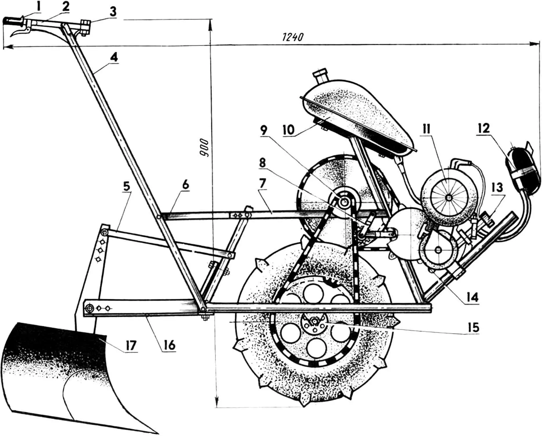
Motor cultivator layout (protective covers removed):
1, 2 — control handles;
3 — M10 bolt with nut (installed in the working position of the motor cultivator, 10 pairs);
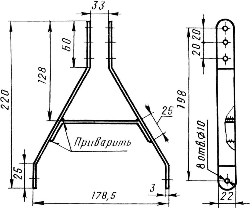
4 — main post;
5 — rod for mounting attachments (2 pcs.);
6 — main post mounting bracket;
7 — frame;
8 — second-stage chain tension mechanism;
9 — intermediate shaft unit;
10 — fuel tank;
11 — fan;
12 — muffler;
13 — air filter;
14 — D4 engine;
15 — drive wheel unit;
16 — attachment mounting bracket;
17 — working tool (cultivator or compact plow).
The motor cultivator is assembled on a welded frame, where the engine with an air cooling system, muffler, air filter, and starter from the “Druzhba” chainsaw are installed, as well as the fuel tank, intermediate shaft of a two-stage chain drive, drive wheel, and bracket for attachments.
There are no problems with storage and transportation, since the motor cultivator is foldable. First of all, you need to unscrew the top M10 bolt (see the diagram of the arrangement of units and parts) and fold the control handles along the top post. Then, after unscrewing a pair of nuts and removing the corresponding bolt from the bracket securing the main post to the frame, turn the bracket and, tilting the post forward until it stops against the channel cross member of the frame, proceed to the next two elementary operations: disconnecting the attachment mounting bracket (unscrew three bolts from below) and removing the drive wheel. After loosening the tension, you can also remove the chain connecting the drive wheel to the intermediate shaft of the two-stage drive, and then, after slightly unscrewing the nuts securing the drive wheel axle, release it from the slots. Converting the motor cultivator to working condition — in reverse order.
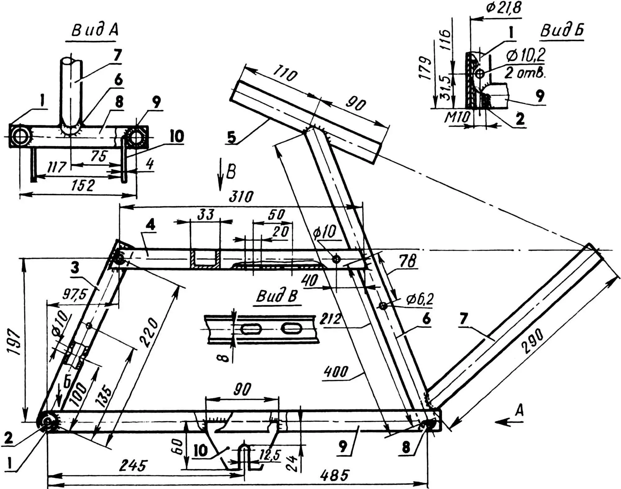
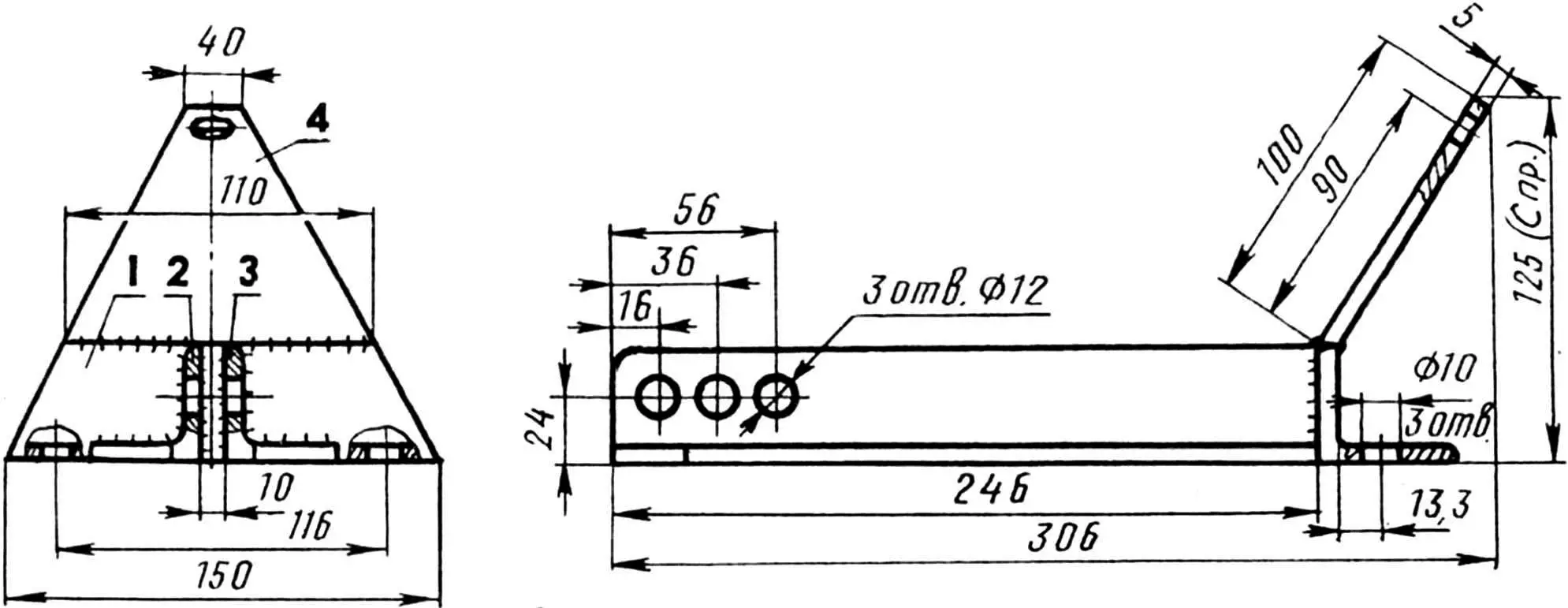
1 — rear cross member;
2 — bushings (steel St3, 2 pcs.);
3 — rear post;
4 — frame guide beam (bent channel, 33×23.5×3 mm, steel);
5 — fuel tank support;
6 — middle post;
7 — front post;
8 — front cross member;
9 — side members;
10 — drive wheel axle brackets (steel St3).
Note:
Parts 1, 3, 5, 6, 7, 8, and 9 are made from steel pipe with a diameter of 26.8 mm, wall thickness — 2.5 mm.
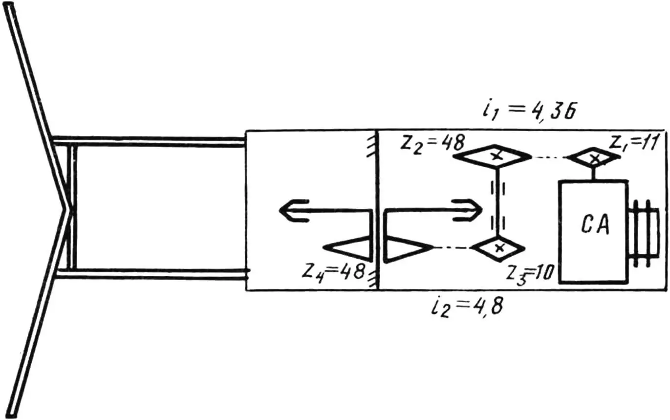
Among other design features, the chain tension adjustment system should be noted. In the first stage, adjustment is performed by moving the intermediate shaft unit along the frame guide beam. First, you should loosen the two nuts of the clamping collar securing the intermediate shaft. Then move the shaft together with the clamping collar along the guide. And after finding the optimal position, firmly secure it. Only after that, tension the second stage of the chain drive using a special sprocket.
The ball bearings of the intermediate shaft are fixed in the axial direction by spacer bushings, which are installed between the corresponding sprocket hubs and bearings. The sprocket z2 = 48 is taken ready-made from an “adult” bicycle (only the pedal levers are cut off). Together with the hub, it is secured on the intermediate shaft with a key. The sprocket z3 = 10 is from an old modification bicycle engine (after preliminary unriveting, it is welded to a homemade hub and fixed on the axle with the same key).
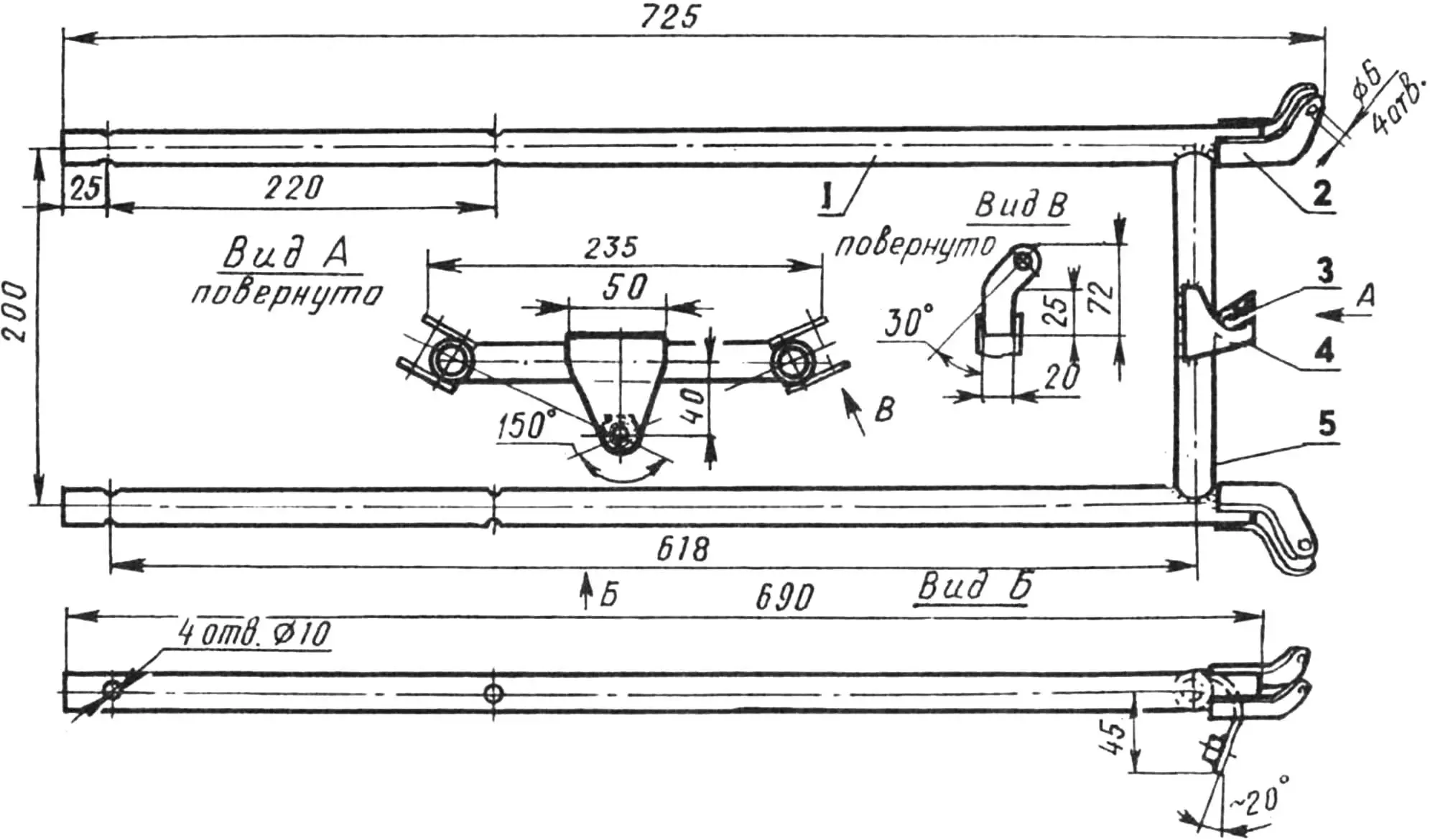
1 — side members (steel pipe Ø21.3×2.5 mm, length 690 mm, 2 pcs.);
2 — side handle brackets (steel St3, 3 mm thick sheet, 4 pcs.);
3 — M10 nut;
4 — central bracket (steel St3, 3 mm thick sheet);
5 — cross member (steel pipe Ø21.3×2.5 mm, length 200 mm).
The chains are bicycle chains, but if possible, it’s better to replace them with stronger ones. For example, from a moped or motorcycles “Minsk”, “Voskhod” (the pitch of these chains is the same).
Now about the drive wheel unit. The sprocket z4 = 48 here is also a bicycle one. It is attached to the outer flange of the hub with six M6 bolts. And the drive wheel disk, made from a 15 mm thick steel sheet, is screwed “tightly” to the inner flange of the hub with M8 bolts.
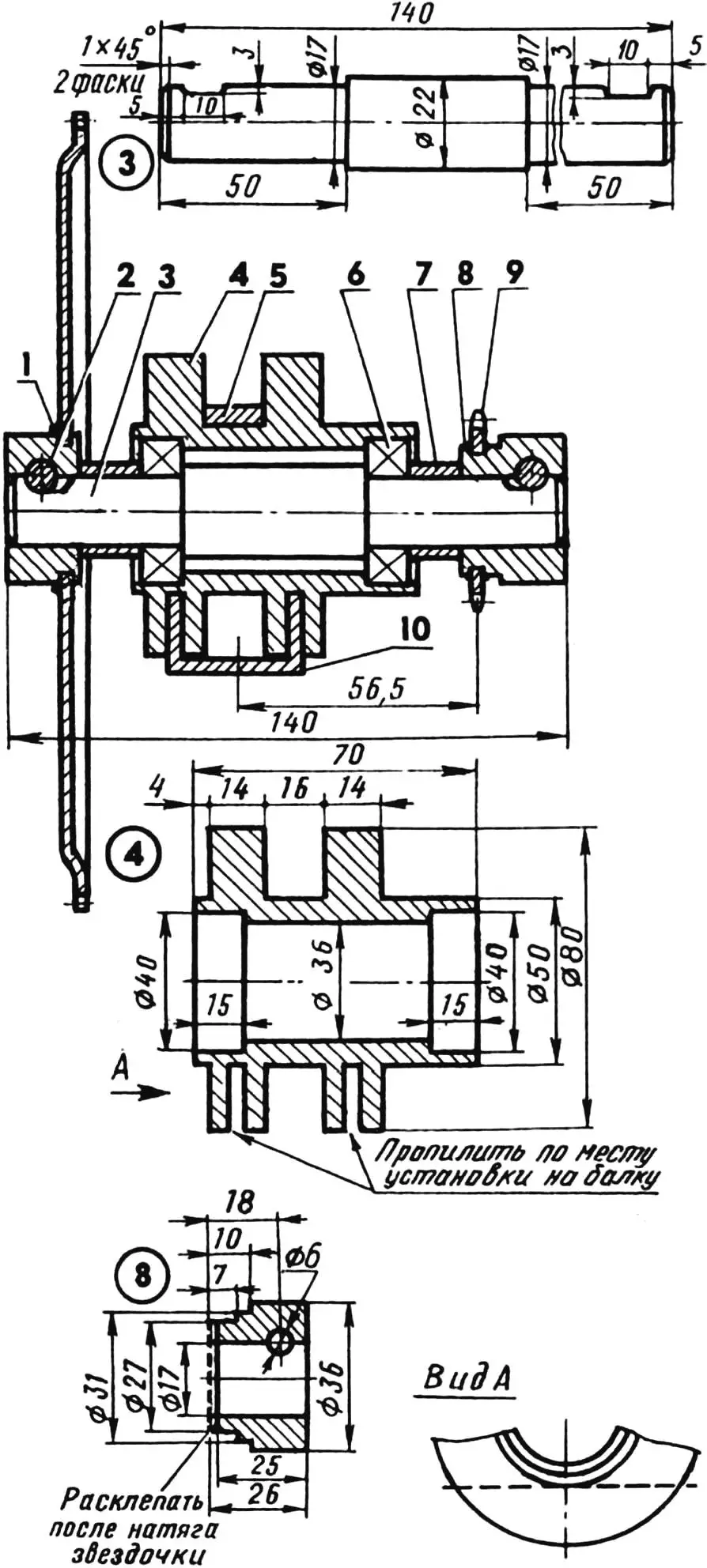
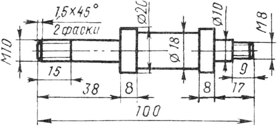
1 — hub with pressed bicycle sprocket;
2 — mounting keys (2 pcs.);
3 — intermediate shaft (steel 45);
4 — housing (steel 20);
5 — frame mounting clamp (spring steel);
6 — ball bearings 80203 (2 pcs.);
7 — spacer bushings (steel pipe, length 12 mm, 2 pcs.);
8 — hub (steel 45);
9 — sprocket from D6 engine;
10 — frame beam.
The drive wheel has eleven welded lugs with a “helmet” profile. They are made from steel plates 3…5 mm thick. The height of each is 38 mm, the angle at the apex is 110°. The ends of the lugs are cut 18 mm into the wheel disk and welded to it. Nylon (fluoroplastic) bushings are inserted into the hub on both sides, serving as plain bearings.
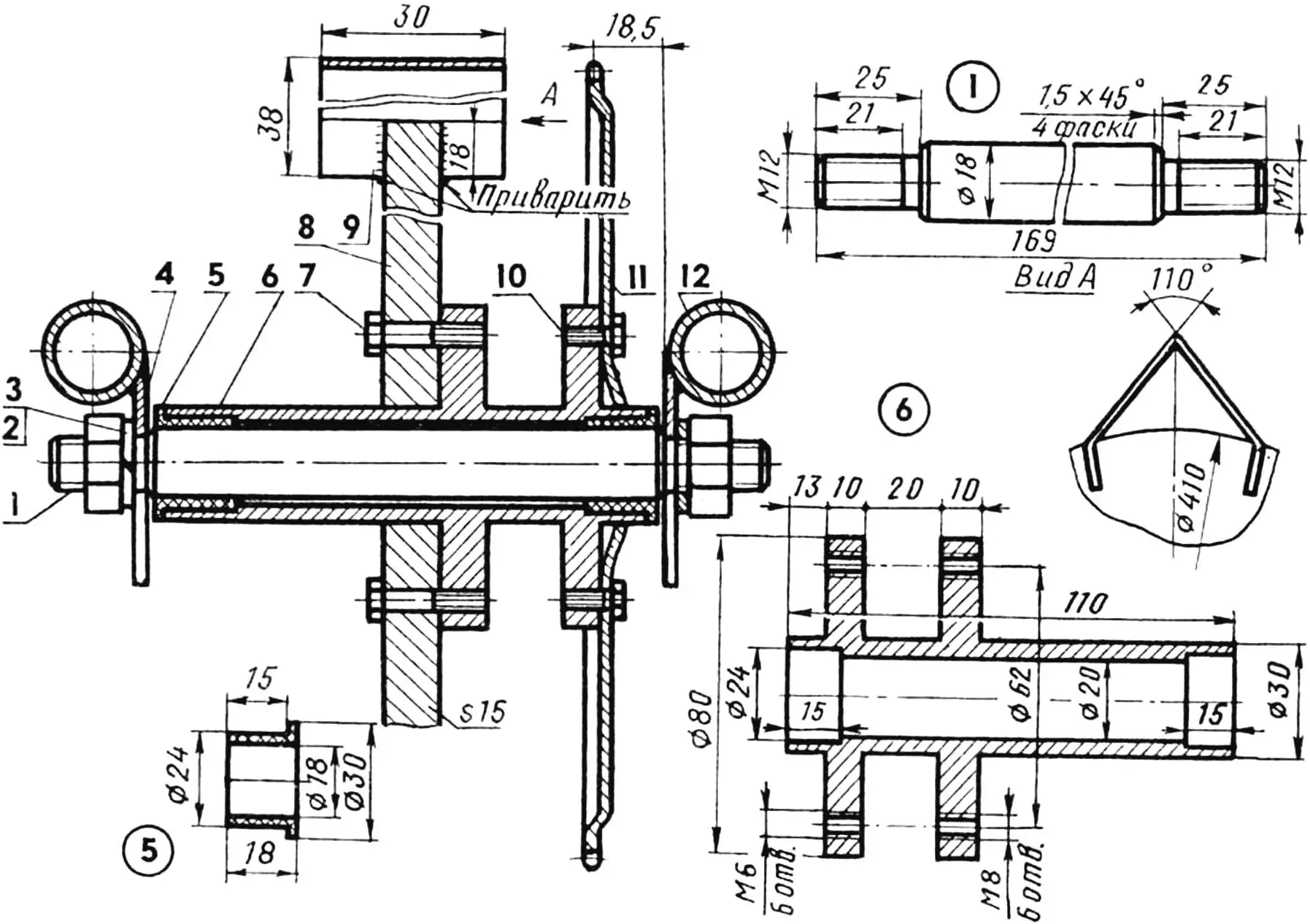
1 — drive wheel axle (steel 45);
2 — M12 nuts (2 pcs.);
3 — Grover washers (2 pcs.);
4 — left side member frame bracket;
5 — bushings (nylon or fluoroplastic, 2 pcs.);
6 — double hub (steel 45);
7 — M8 bolts (6 pcs.);
8 — drive wheel disk (steel St3);
9 — lugs (steel St5, 11 pcs.);
10 — M6 bolts (6 pcs.);
11 — bicycle sprocket;
12 — right side member frame.
The fuel tank is taken from an old motorized bicycle. It is very convenient, as it has a decent volume — 2.5 liters, a good mounting, and a filler neck with a cap that ensures tightness during transportation. One refueling of such a tank is enough to process three plots of land of 6 hundred square meters each.
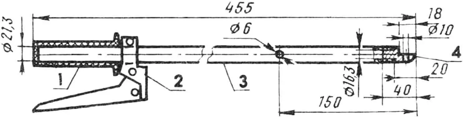
1 — handle (from motorcycle);
2 — clutch lever with latch (for the right handle, a throttle control grip is installed);
3 — rod (steel pipe);
4 — tip (steel St3).
For clutch control, a factory handle with a “disengaged” state lock is used, necessary for starting and warming up the engine. The “throttle” is controlled by a grip from the decompressor of an old motorcycle.
A D4 motorized bicycle engine is used as the power unit of the motor cultivator. It has been modified and equipped with starting and forced air cooling systems. The essence of the modification is that under the bolt securing the drive gear on the crankshaft (on the right side of the engine), a fan drive pulley with a ratchet for the starting system is installed. Everything is approximately as in technical solutions, descriptions of which can be found in “Modelist-Konstruktor” (No. 8’79, 8’84, 2’87, 10’90). The pulley with a rubber belt transmits rotation to the impeller of an axial fan mounted on the engine head. The gear ratio of such a drive is i=0.5. The fan impeller diameter is 110 mm, the number of blades is 6. The fan is mounted on two 200 bearings.
A 2-mm steel plate with a centering (relative to the drive gear) band is screwed to the clutch cover, and a coil with two mounting flanges is attached to the plate. One of them serves to mount the starter from the “Druzhba” chainsaw.
1 — cross member (steel angle 40×40 mm);
2, 3 — left and right links (steel angle 40×40 mm);
4 — plate (steel St3, sheet, 5 mm thick).
In addition, the modified engine has a replaced clutch lever. It is made shaped, since the intermediate shaft drive chain goes from the engine upward, not downward, as on mopeds. For the same reason, the upper partition of the cover covering the drive sprocket is cut out. The exhaust pipe is shortened and turned 180°.
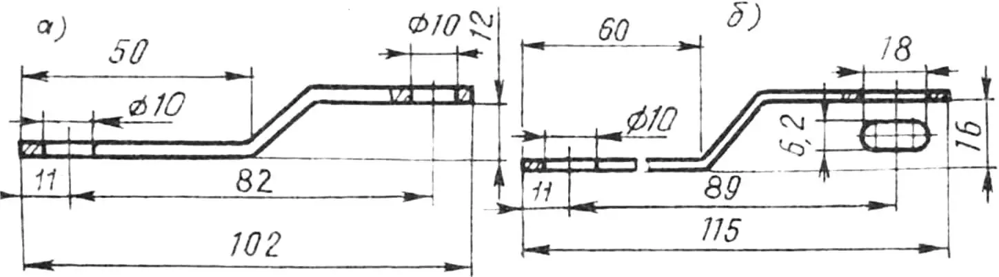
a — lever (St3, strip 22×4, 2 pcs.),
b — lock (St3, strip 20×1.5, 2 pcs.).
A hand cultivator (purchased in a store) with extended sidewalls is used as a hiller. According to publications in “Modelist-Konstruktor”, a small plow was also made, but I haven’t had a chance to test its performance yet. I processed the soil with what I had already become thoroughly accustomed to. Moreover, I tried to help my hardworking motor cultivator move forward at the maximum depth of the hiller. However, the latter is not necessary: you can go over the area being processed twice, but then spending minimal effort. After all, the modified and well-maintained engine develops a fairly large torque. And if something happens — the wheel will simply slip, without overloading the power unit.
And one more piece of advice. When operating the motor cultivator, wash the air filter every five hours of operation — you won’t go wrong.
Motor cultivator technical specifications:
Dimensions, mm:
in working condition — 1240x850x900
in transport position (with drive wheel and attachment bracket removed) — 780x260x600
Weight (without attachments), kg — 25
Working speed during cultivation, km/h — 2
Productivity when weeding between rows, m2/h — 300
Power unit — modified D4.
Cooling system — forced, with homemade fan.
Starting — starter from “Druzhba” chainsaw.
Transmission — two-stage, chain (i1 = 4.36; i2 = 4.8).
A. KOPYEV
Recommend to read
 TREAT THE PEDAL…
Bike pedals used to put a metal screw cap to protect the bearings from contamination. Now, instead, use the plastic plugs, which are often lost. Rescue plastic or nylon tubes from...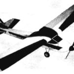 IN FLIGHT — JUST LIKE A REAL…
Control line model plane-vysokoplan. The first simplest kordovye model. made of pair plates, quickly bored novice modelers — they, of course, want to raise in the air like a real...
