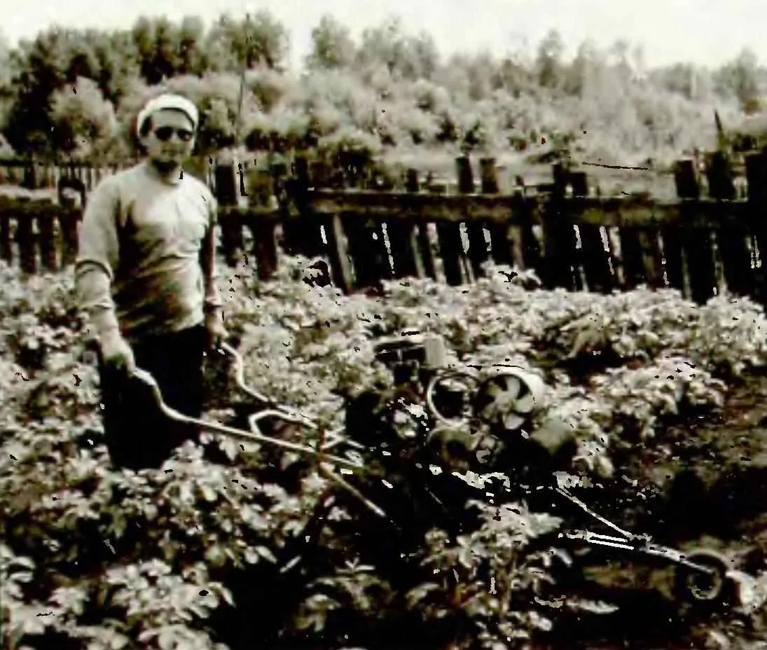
 Tell us about your garden “helper” – a self-propelled motorcyce-cultivator with gauge device the Main purpose of this soil-cultivating Assembly is in the care of plantings of potatoes: post-harvest processing between rows to remove weeds, loosening the soil, hilling plants.
At the stage of choosing construction and design have read several articles of a multi-year subscription of the magazine “modelist-Konstruktor”, devoted to the means of mechanization is not considered shameful and even like to use ready to develop successful designs, which were published on the pages of the publication the Main thing is not to engage in blind copying, but a creative enterprise, armed with the most interesting technical solutions and develop them further.
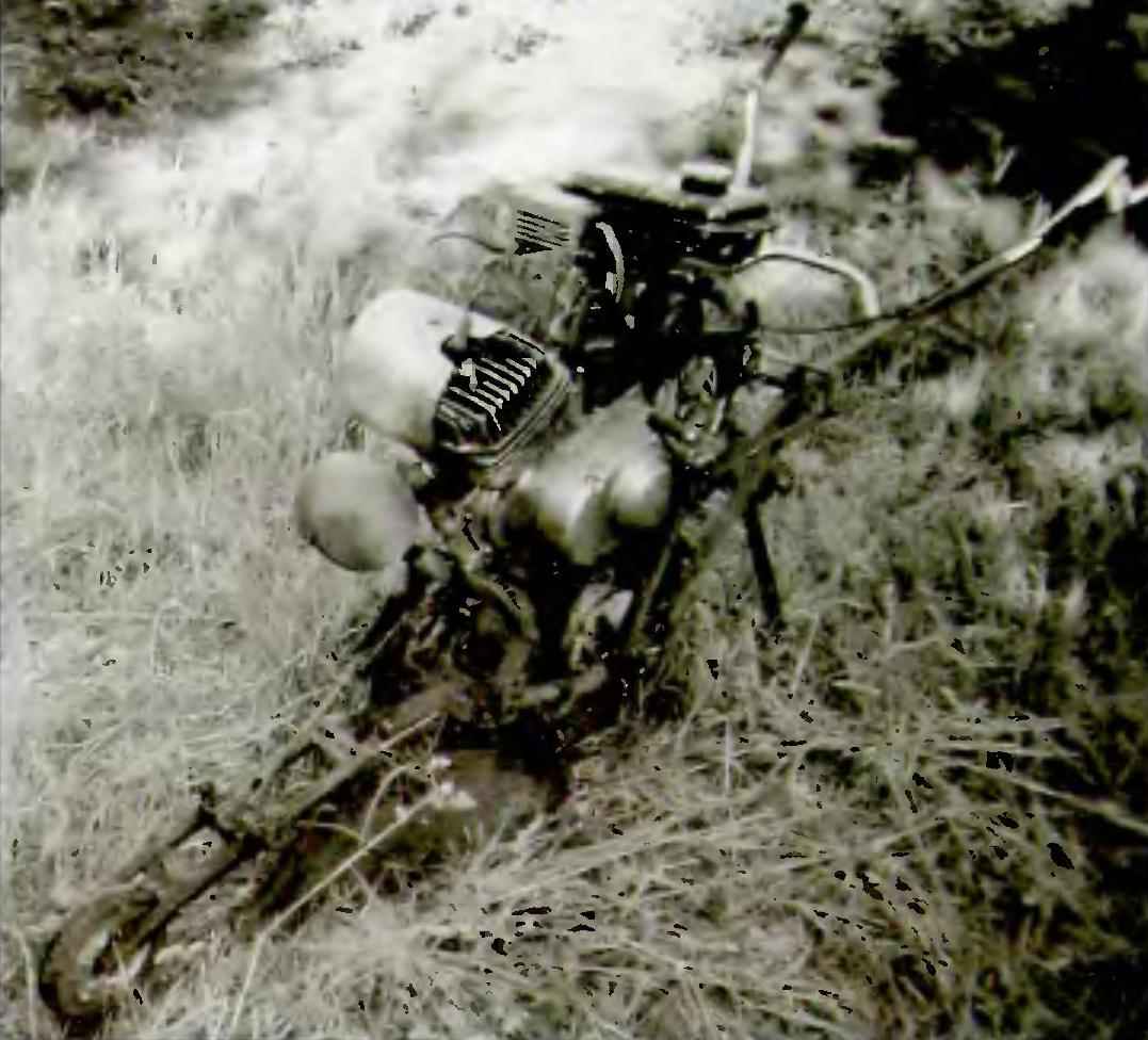
In the first issue of 1985 of the magazine “modelist-Konstruktor” from a publication called “push-push in the garden” I learned about tillage unit is not the usual scheme of the working body — it was set between two wheels arranged in the longitudinal direction as the bike or motorcycle to the Author, E. Pedriks from Estonia, very lucidly explained the advantages of such a scheme will Briefly repeat them.
During the work of the trimmed shingles Hiller layer of the earth and presses on the driving wheel, contributing to its adhesion to the soil
Jockey wheel in front of the working body performs several important functions: it is the directing; to preset the depth of penetration of the working body in the soil; automatically maintains it in the process of processing the rows: copies the microrelief of the plot.
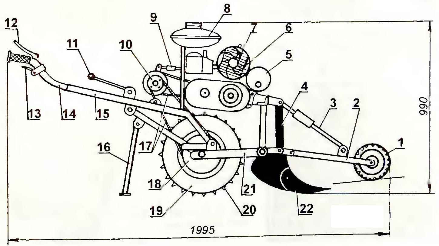
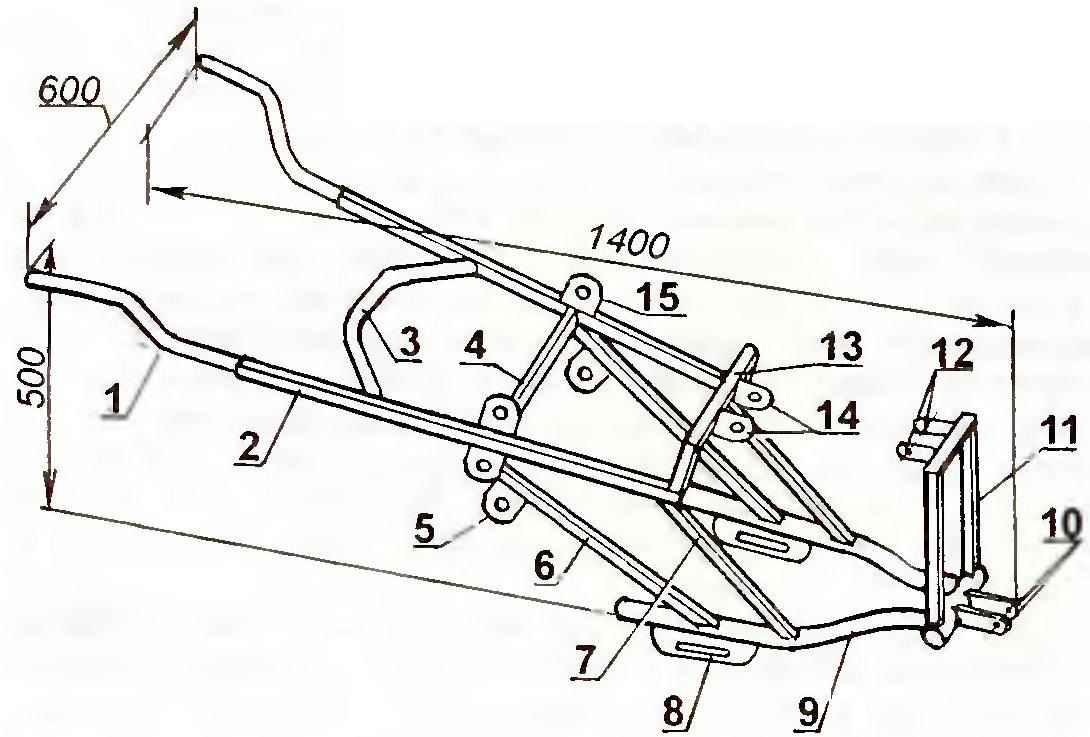
Garden cultivator-Hiller:
1 —the sending (copying) the wheel (from a children’s pedal cars);
2 —plug of the idler;
3—way adjustable strut-lanyard;
4—replacement tillers (Hiller, cultivator, Ripper),
5—muffler (housing blowtorches);
6— fan forced cooling of the motor casing,
7—the engine (from a motorcycle MMVZ-125);
8— fuel tank V = 8 l;
9—turnbuckle for tensioning a chain drive;
10 intermediate shaft;
11—the lever of switching of speeds;
12 — the lever-the trigger clutch (located on left arm);
13 coin of the throttle (located on the right arm),
14— control lever Hiller (from a motorcycle MMVZ-125, 2 PCs.);
15 —Rama.
16—stand;
17— the chains of transmission,
18, the drive sprocket of the drive wheel;
19— driving wheel of the scooter Tulitsa;
20 bandage (area 20×20);
21— plug drive wheel (scooter “True”);
22— working on(Hiller)
As the driving wheel is oriented in the longitudinal direction with the guide Assembly is in a furrow on rails under the drive wheel is Neutrik-industrial soil — solid track.
This idea of linking self-propelled unit so I liked that formed the basis for the design of my “helper”. Processing of potato land for eight seasons, has only confirmed the correctness of my choice.
Kinematic scheme of transmission:
1 — power unit (from a motorcycle MMVZ-125);
2— sprocket of the output shaft (z = 14);
3— circuit of the first stage (t = 15,575);
4— large intermediate shaft sprocket (z = 41);
5— small dvuhventsovye asterisk intermediate shaft (z = 9);
6— the intermediate shaft bearing (2 PCs )
7—devetia circuit of the second stage (t = 12,7)
8— drive sprocket of the drive wheel (z=38)
9— driving wheel (scooter Tulitsa)
10— bearing drive wheel (2 PCs , staff, scooter Tulitsa)
 Now more about that is a given tillage machine the Machine is quite well-composed of the usual motorcycle, motoroller and automotive parts.
Controls Assembly — motor type: to the rear ends of the side members of the frame are welded halves of the bellcrank steering of the motorcycle with the handles and control mechanisms On the right lever is the lever-coin adjust fuel delivery on the left — lever-trigger clutch. That’s just the gear shift is carried out in car — handle located on the frame in front of the driver Arm is connected through the axis, and Z-shaped rod, with the shaft of the gearshift mechanism.
The frame is made mainly of steel pipes of square section 25×25 mm. it is located On the intermediate shaft transmission, controls attached to them working bodies. Most of the brackets and auxiliary parts (e.g., front gas tank, etc.) cooked in place when the layout and Assembly of components and assemblies in a single structure In the drawing frame, they are conventionally not shown.
Frame:
1 — the lever of a wheel (a motorcycle MMVZ-125, 2 PCs.);
2—spar (tube 25×25, 2);
3— rear crossmember (from the handlebar of the motorcycle MMVZ-125),
4— the average cross member (tube 25×25);
5— lug axle stand (steel sheet s5, 2 PCs.);
6 — brace (tube 25×25, 2);
7 —inclined strut (tube 25×25, 2);
8 — mounting bracket wheel (steel sheet s5,2 PCs.);
9—plug idler wheel (swing arm of the scooter “True”);
10— eye for connection of the copier (sheet s5);
11 — the portal front motor mount (tube 25×25);
12— eye for attaching the front of the engine (sheet s5);
13 —the rear portal engine mounts (tube 25×25).
14— eye for attaching the rear of the engine (sheet s5);
15— eyelet arm gear (steel sheet s5, 2 PCs.)
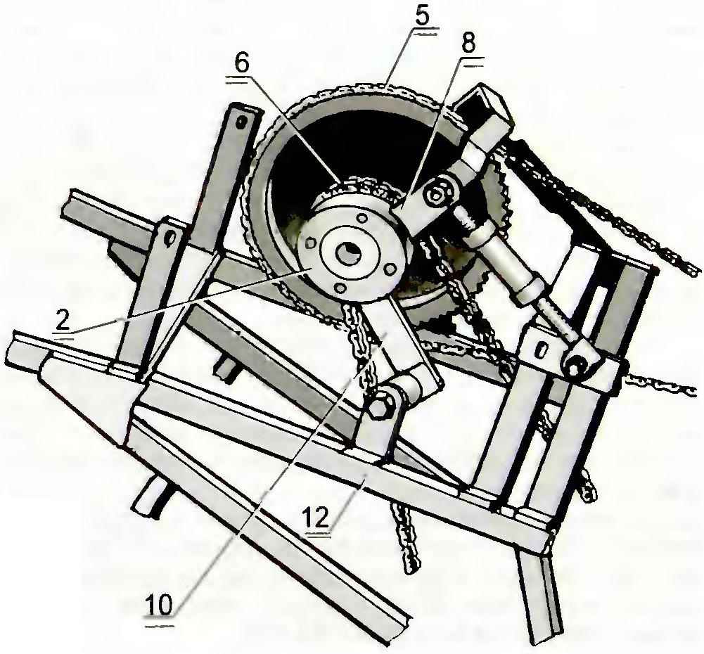
Here I will note that mounting of the intermediate shaft on the frame turned out to be quite intricate, since it was necessary to exclude the touch of the chains of transmission on parts of the frame and simultaneously provide the possibility of moving the intermediate shaft to their tension if necessary. Therefore, this article though here is the drawing of the intermediate shaft (he raises no objections), it mounts on the frame are only as a guide to action Might be, who decided to make a similar design will find a more simple solution!
The basis of the same frame was a pendulum suspension fork rear wheel of the scooter Tulitsa. From him and drive wheel motor-cultivator For increasing adhesion of wheels with the soil on the “treadmill” tread of the tyre is installed a metal brace with the cleats of angle angle 20×20 mm. the Brace is a wrap of the two half-rings, bent from steel strip 30×5 mm cross-section of the Washer from one side are connected by a welded joint of a door hinge, and on the other hand tightening the M10 bolt once installed on the tire.
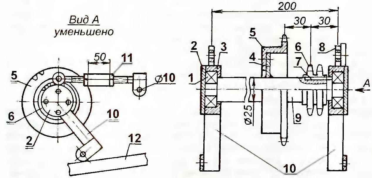
Intermediate shaft:
1 —bearing No. 17 (2),
2— housing cover bearing (2 PCs.);
3— the bearing housing (2 PCs)
4 — flange mounting of the large sprocket;
5 — big star ( z=41)
6—small (dvuhventsovye) sprocket (z= 9);
7—key;
8— lug for tensioning valuable transmission (2 PCs.)
9— intermediate shaft;
10— crassane connecting the node to the frame;
11 — turnbuckle for tensioning the chains of transmission (“setting”);
12 — Rama
Wheel hub main wheel was used in the collection, only in the hub of the sprocket was installed a new bearing No. 60205 protected the puck from dust Dural die-cast housing sprocket was removed.
Engine MMVZ-125 motorcycle “Minsk” for Hiller was chosen because it was available. Previously, he stood on a makeshift walk-behind tractor, which was not just idle.
The engine is equipped with forced cooling system it Looks like this’ and the cylinder of the engine under the head to the cooling fins bolted with M4 plug placed on the end of the bearing hub, the axle, a fan and a follower pulley And the pulley is placed and fixed on the extending crankshaft (or rather its sequel, the generator rotor) the stud MB (same as mount of the cylinder to the crankcase).
As a “belt” to drive the fan to use a rubber o-ring cylinder diesel engine JAMZ-238 — it does not even require a mechanism (or device) tension To supply a more intense flow of air on the cylinder was installed fan shroud made from a piece of galvanized sheet metal, it is mounted on the cylinder is effected by four springs.
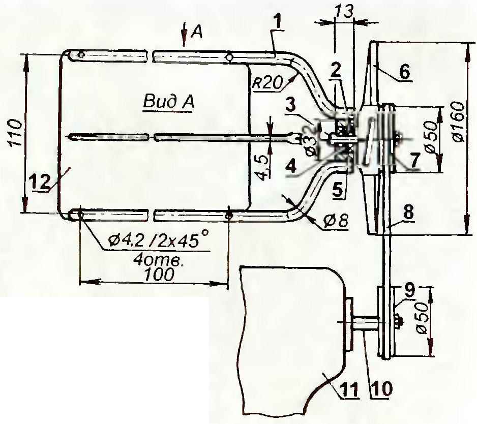
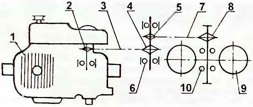
System forced air cooling engine cylinder:
1 feather plugs (steel wire d8, 2);
2— bearing No. 17 (2 PCs.);
3 — axis impeller (steel);
4 — spacer sleeve;
5 — bearing housing;
6—impeller;
7 is driven pulley,
8 — the drive belt (rubber o-ring piston diesel engine YAMZ-238);
9 — drive pulley;
10 — extension stud M6;
11 —Carter the generator
12—fin cooling engine cylinder
The engine is mounted the carb and air cleaner “drum” type of motorcycle M-103 Carburetor attached to the cylinder via a homemade adapter. Electronic ignition system — standard as a result of all the improvements the engine has become more reliable, easier to start and has good traction.
Power system engine is extremely simple — the fuel to the carb the Fuel tank flows by gravity from the system pre-start heating of engine of car ZIL-130, and is fixed with the help of clamp on the pipe cut, rear mount motor MMVZ-125.
The power unit is located above the drive wheel, but slightly offset to the right it is Fixed on the frame by means of two paired stands.
Transmission of Hiller includes a two-stage chain drive, the first step is asterisk: ZT = 14 teeth Z2= 41 tooth, and the second Z3 = 9 teeth, Z4 = 38 teeth.
Intermediate shaft transmission mounted behind the engine. Its ends mounted in bearings No. 60204 bearing located on racks with adjustable rods that allows the tension of the two branches of the chain gears at the same time.
Exhaust system of the engine consists of two parts, cut the knee of the exhaust pipe with nut and silencer of the body of blowtorch, allowing for maximum compactness with good performance in noise reduction, without compromising power Lever kick starter — regular, motor.
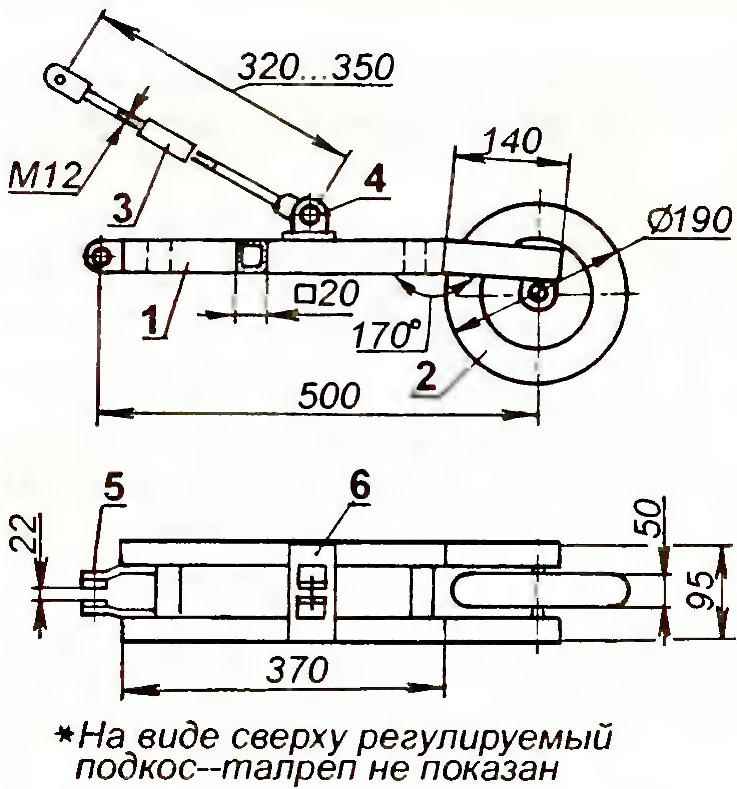
Copier:
1 —frame (tube 20×20);
2 — gauge guide wheel;
3—adjustable brace-turnbuckle M12;
4 — bracket for connecting the brace-lanyard (25×25 area);
5 — lug to connect the copier to the frame (steel, sheet s8);
6—tool tray mounting bracket (steel, sheet s8)
Frame copying mechanism was made of square tube Adjustable rod “copier” is made of a rod with a diameter of 12 mm and has two lanyard Jockey wheel — “sulker” from children’s pedal cars, perfectly fit into the overall layout of the Hiller-cultivator.
Replacement tillage operation unit is securely fixed with bolts M12 at two points. The first (lower) fastening point (or rather the suspension of the tool on the bolt-axis) is at the end of the pendulous fork and formed from two elongated ears. The bracket-lugs of the second (upper) mounting points welded to the front of the frame (near the front mount of the engine). To them front working on podstugivaniya through a small turnbuckle that allows you to adjust the angle of attack of the weapon. On connecting (or disconnecting) a working body requires 10 to 15 minutes.
Safety when working on the tillage unit completely solved, and the task of the farmer is only in machine operation and visual inspection of processing quality. Processing area is on the 1st transfer, subject to the normal requirements of machinery In the processing of such tandem self-propelled Hiller-cultivator little help withstand the rectilinear direction of movement and depth.
In the case when clipped a heavy layer of earth or lump will slow down the movement of the unit driving wheel just begins to “mill” the ground, gradually going deeper in her out of this situation is quite simple, you need to reset the engine speed by pushing the control knob from the top down, withdraw from working on the land, thus freeing it from the ballast and providing a load on a driving wheel Adding fuel, Hiller will be released to the original position and continue processing area.
Rotation of the mouldboard can be made on the spot, when fully depressed the clutch, and during movement of the unit by tilting it in the direction of rotation, thus the working body should not come into contact with the soil, In practice, convinced that it is better to work for long stretches — less tired, and the fuel savings are significant.
A relatively small weight (about 70 kg), a single-track, rational layout of all the organs allow a land area of 0.15 ha to treat during the 45 — 60 minutes, especially without straining.
For care of plantings of potatoes depending on the type of processing used various tillage equipment For loosening the top layer of row spacing and pruning of the weeds in the front holder set cultivator for hilling — replace it with Hiller During the first pass of the unit check the actual depth and quality of processing.
When hilling potatoes Hiller needs to pour a smooth layer of earth on the whole comb with prisalivaya it to the stems of plants and loosening the sides and bottom brosdi.
A. yakishev in a, p. -15 Yeniseisk, Krasnoyarsk Krai
Recommend to read
 TRIPLE LASER
Recent studies have shown that laser beams act on the seeds of agricultural plants as an active stimulant, arousing in them the reserve force, increasing productivity, zastausia from...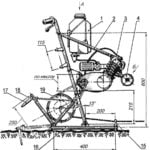 RIDING ON THE WINCH
In this release, "M-K" we want to acquaint readers with one of the most effective tilling mechanisms, which has recently been gaining more and more popularity among Amateur designers....
