
 Increasingly, in an editorial post meet the voluminous packages of drawings and descriptions of improvised microvesicles. Their fundamental difference from development of previous years — a successful combination in the construction standard and improvised units. The second important detail — the sharp improvement in appearance, a bold design decision.
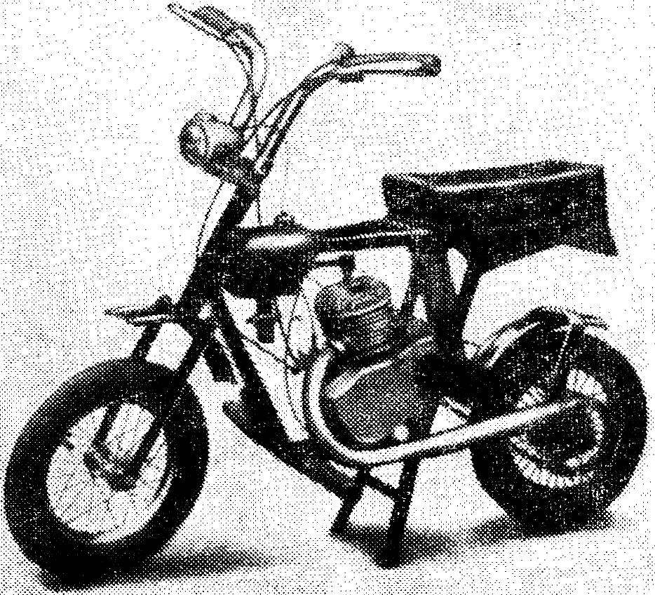
On these pages we present to the readers micromatics, which fully include the characteristics described above.
Developing the layout of your microvesicle, I came to the conclusion that the fuel tank can be made an integral part of the power frame. This gave the opportunity to reduce the weight of the machine and give it a more dynamic shape. Application for oval frame tubes allowed to make “Grasshopper” strong enough, easy and, most importantly, small size. When folded the wheel of his dimensions fit into a box 195x750x1050 mm, which allows it to freely accommodate the trunk of the car, in the Elevator, and even under the bed.
This microvesicle frame is welded from thin-walled (with wall thickness up to 1.5 mm) steel pipe. All the elements of the frame (except the fuel tank) are connected by welding, not immediately, but gradually individual nodes with intermediate straightening, because the leash was significant. Parts fuel tank was connected by gas welding.
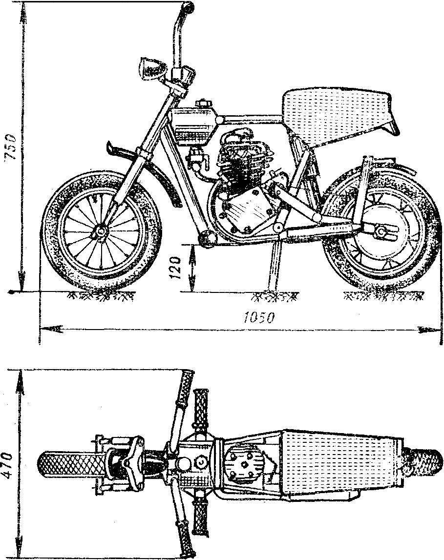
Fig. 1. General view of microvesicle.
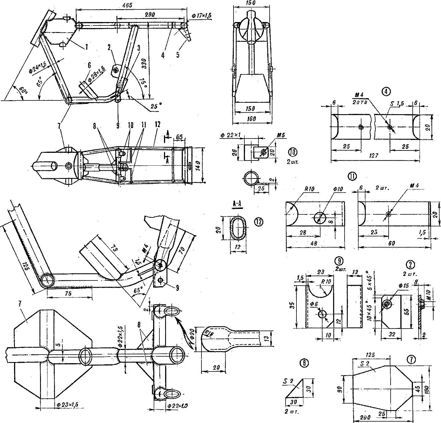
Fig. 2. Frame microvesicle “Grasshopper”:
1 — fuel tank 2 — solitaire-bracket, 3, 6 — brackets engine mounts, 4 — strap attachment tool kit, 5 — canopy, 7 — shield-reflector-8 — gusset plate, 9 — mount stand, 10 — clip 11 — upper bracket rear shock absorber, 12 — oval pipe.
And now more about the bike and the manner of its Assembly.
The gas tank is not only a fuel bottle, it and the power element of the frame. It is based on steel pipe Ø 102X1,5 mm. After marking and trimming welded thereto a pipe with a diameter of 20 and a length of 108 mm. and Then at the end of the device superimposed steel plates, outlines in his contours, cut and welded.
Next, adjusted the head frame is welded, n in case cut the holes for the tank filler and drain fitting of the fuel, which are then soldered into the tank.
Made telescopic front fork, spring shock absorbers. The bridge plug is machined on a lathe, then milled and reams and rastaquouere hole. The axis of the bridge plugs, covers telescopic shock absorbers and the tips of the feathers pressed into the bridge and opasayutsya brass. When assembling the pens of the fork fills with grease.
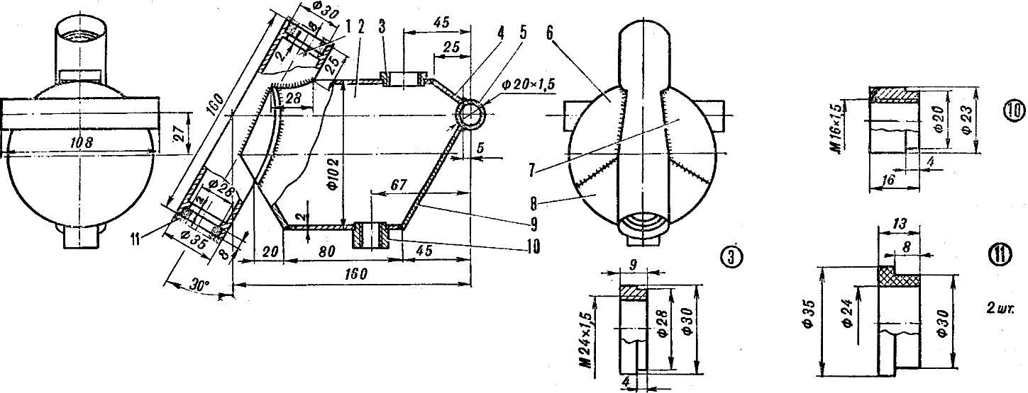
Fig. 3. Gas tank:
1 — head frame, 2 — tube (Т102х1,5, l = 140), 3 — neck, 4 — panel, 5 — tube (Т20х1,5, l = 108), 6-9 — pads, 10 — nozzle, 11 — support sleeve.
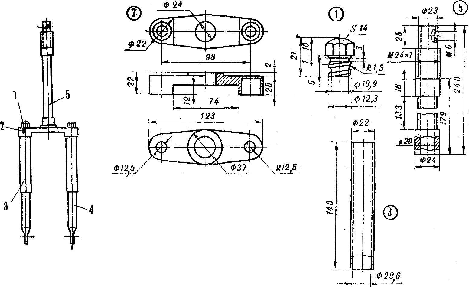
Fig. 4. Front fork:
1 — the bolt 2 — the bridge plug, 3 — absorber, 4 — pen plug, 5 — steering shaft.
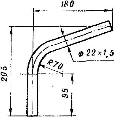
Fig. 5. The wheel.
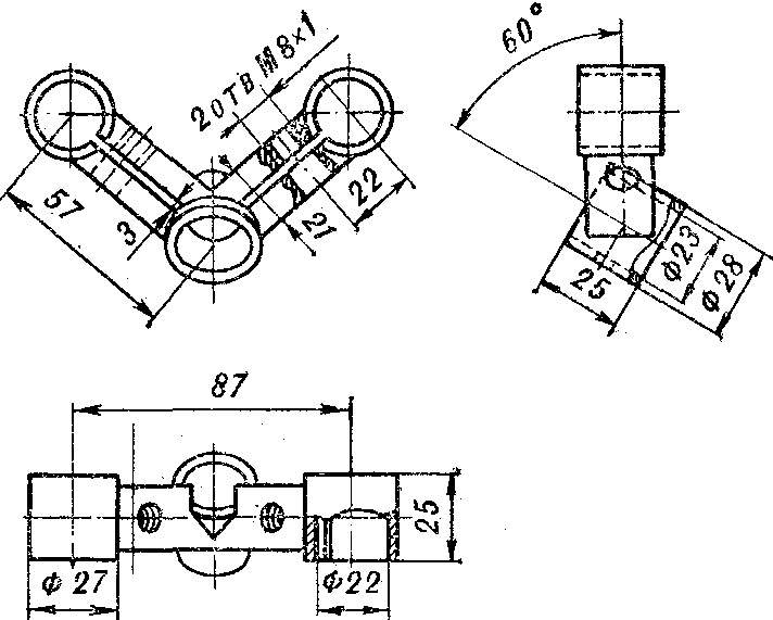
Fig. 6. The bridge helm.

Fig. 7. The rim of the wheel.
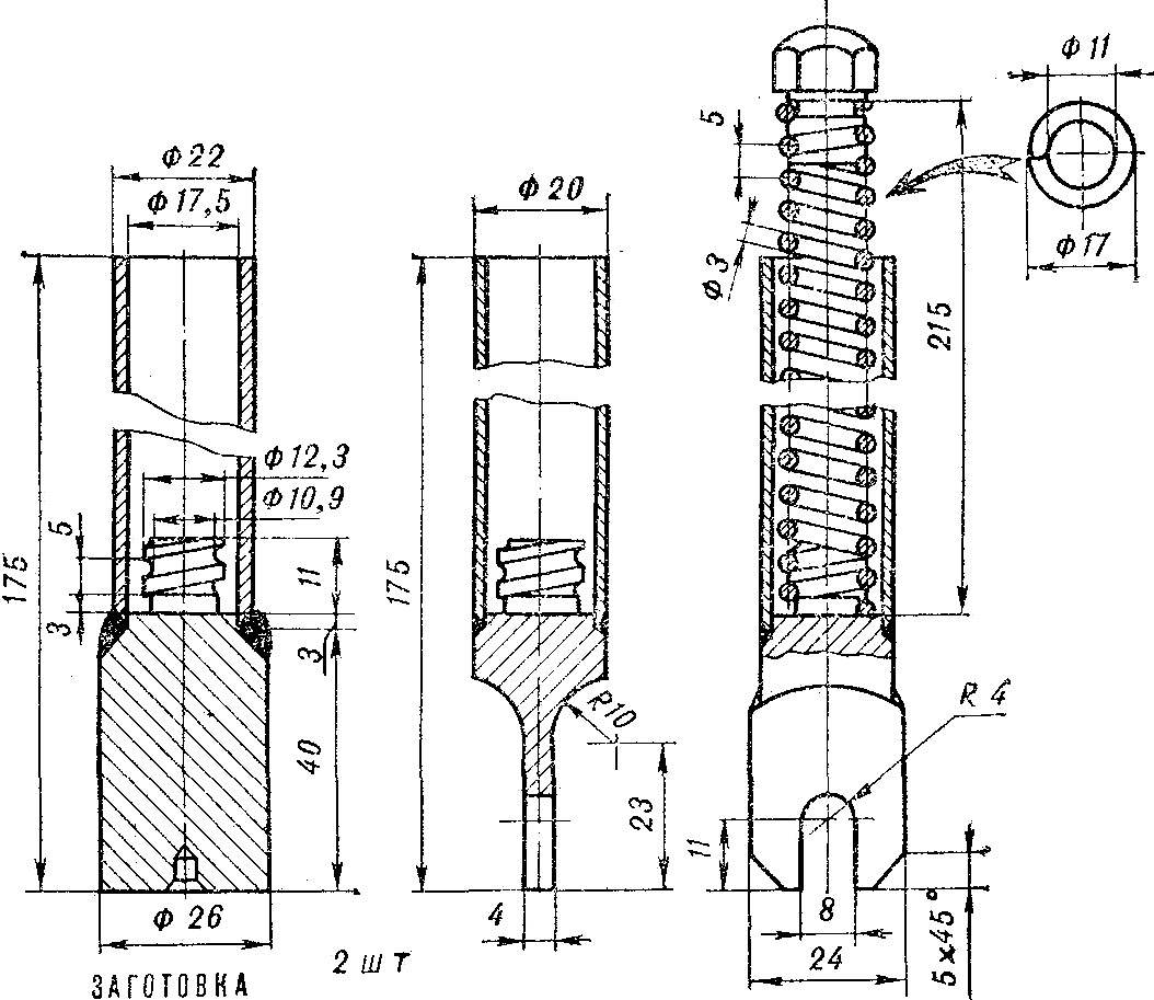
Fig. 8. The feather of front fork.
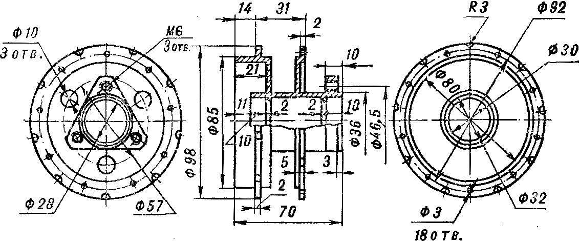
Fig. 9. Hub rear wheel.
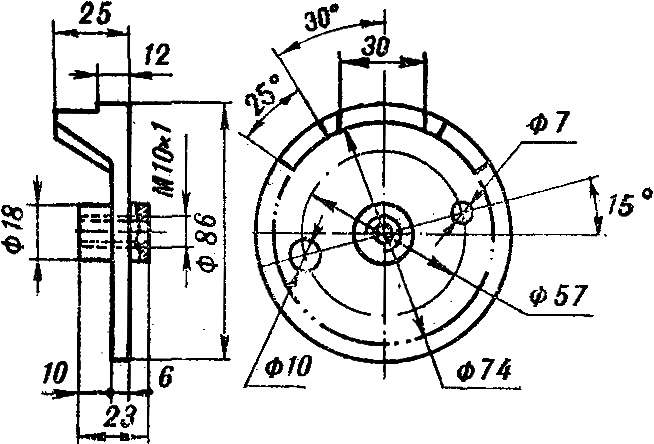
Fig. 10. Brake drum.
Pendulum fork rear suspension also homemade. To the frame it is secured by two M8 bolts in the place where the axis of the drive sprocket. The bolts must be strictly aligned to each other.
Wheel designed for the standard samokatnaya tires. Rims homemade, chiseled. The hub and spokes of the front Bicycle wheel and rim rear wheel connects with a homemade hub eighteen spokes of the wheel of a moped “Lviv”.
Brake drum and pads made of aluminum alloy D16T. Each pad is machined on a lathe with the subsequent drilling and milling. Made thus pads aluminum wire riveted friction lining.
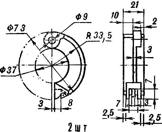
Fig. 11. Brake pad.
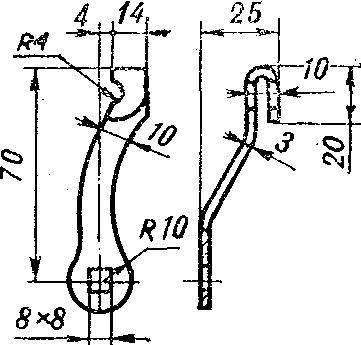
Fig. 12. Brake lever.
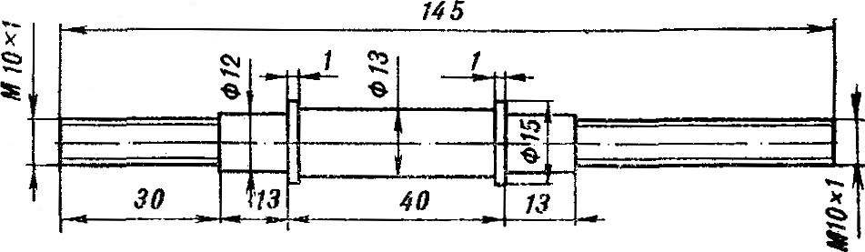
Fig. 13. The axis of the rear wheel.
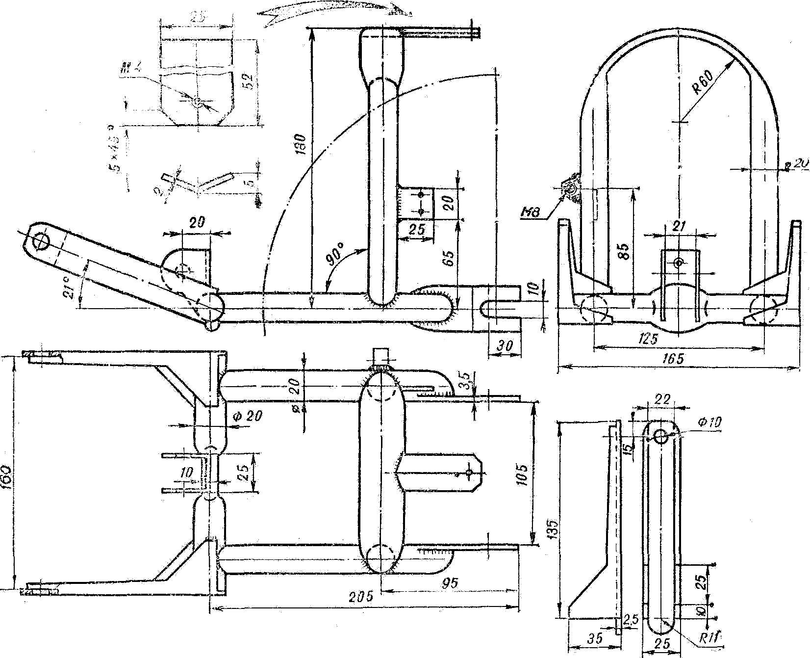
Fig. 14. Rear suspension.
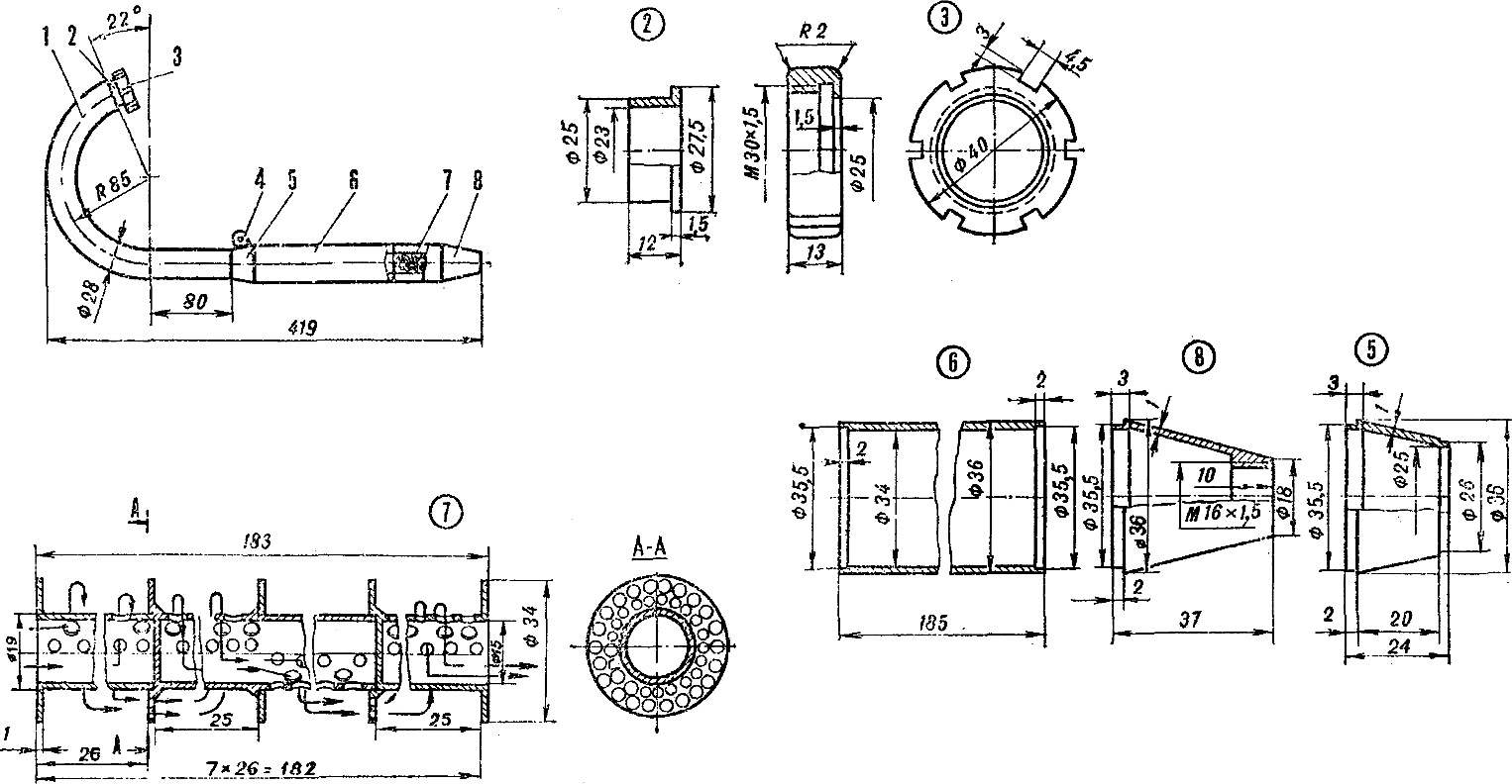
Fig. 15. Exhaust pipe:
1 — knee, 2 — reducer sleeve, 3 — nut, 4 — ear, 5 — cone 6 — muffler pipe, muffler, 7 — insert silencer, 8 — cone.
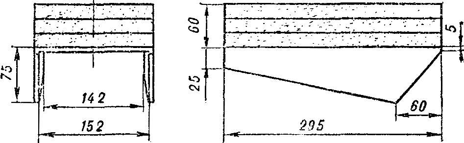
Fig. 16. Seat.
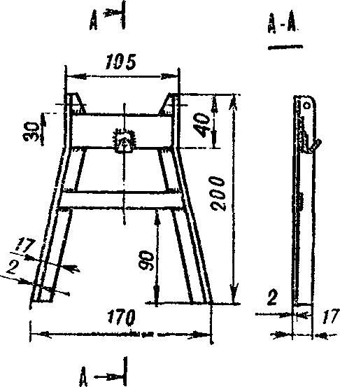
Fig. 17. Stand.
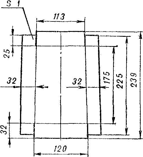
Fig. 18. Tool kit (scan).
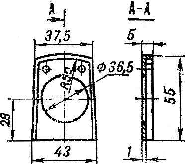
Fig. 19. Frame.
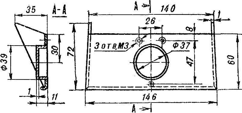
Fig. 20. Visor.
Exhaust pipe is picked from the regular knee-engine sh-58, bushing and muffler. The knee is being finalized — it should be bent as shown in the figure.
Motorcycle seat — sheet duralumin, polyurethane foam, dense fabric and faux leather in black.
Tool kit hidden under the seat of microvesicle. It is made of sheet aluminum with a thickness of 1 mm.
The Color “Grasshopper”. After welding the frame thoroughly cleaned, removed rust, slag and spatter. Then it should be primed and then painted in several layers. The color depends on your ability and taste. For example, I used the black nitroenamel and to the tank through a stencil depicted nitro white silhouette of a grasshopper. Exhaust pipe, feathers, forks, hub rear wheel, bridge wheel and rim chrome.
A. LYKOV, Leningrad
Recommend to read
 THE WILL OF THE DESIGNER
At the end 1940-x of years in several countries of Europe, a dilapidated Second world war, gradually began to recreate the automotive industry. On the streets there are inexpensive micro... SCRUBBING FLOORS, WITHOUT A BUCKET
To clean very dirty floors in commercial premises or to refresh a larger area, including the site with asphalt or tile floors, a country or a plot, will allow that such scrubber brush....
